Tideway Central – Victoria Embankment (2024)

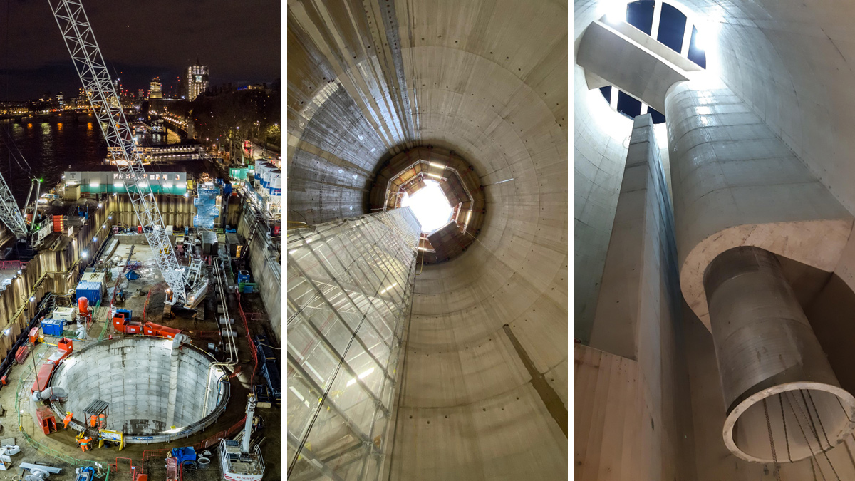
(left) A view of works underway at night, (middle) secondary lining complete, and (right) view from the base of the CSO drop shaft - Courtesy of Barhale
The Thames Tideway Tunnel project is a 25 km (16 mile) combined sewer under construction under the tidal section (estuary) of the River Thames as it runs through London. It will significantly increase the capacity of London’s sewerage system, large sections of which were built in the 19th century, and be able to capture, store and convey almost all of the raw sewage and rainwater that currently overflows into the Thames Estuary. The Tideway tunnel will connect 34 of the capital’s most polluting combined sewer overflows (CSOs), transferring the foul water to the Lee Tunnel for onward delivery to Beckton Sewage Treatment Works. The completion of the Thames Tideway Tunnel scheme, currently anticipated for 2025, will significantly improve water quality, capturing more than 95% of the spills that currently enter the river to the benefit of London’s almost 9 million residents.
Location
As part of works on the Central section of the Thames Tideway Tunnel scheme, Barhale was contracted by the Ferrovial and Laing O’Rourke joint venture (FLO JV), the lead contractor for the central section of the project, to deliver the heavy civils and civils structures that would intercept the sewage overflows and transfer these to the main Tideway tunnel beneath the river Thames.
The Victoria Embankment site was located in the City of Westminster, on the north side of the river Thames adjacent to, and south-west of, the Hungerford Bridge and Golden Jubilee footbridges. The site was bounded to the south-east by the River Thames and the north-west by the A3211, beyond which are the Victoria Embankment Gardens.

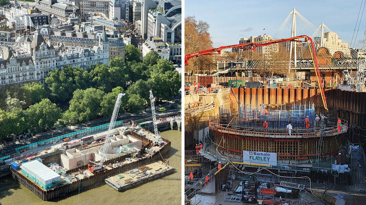
(left) Works within the cofferdam in the Thames and (right) works ongoing within the cofferdam – Courtesy of Barhale
Scope of work
The works were delivered in stages to provide protection to existing assets and engineering control over the structure’s movement. One of the first elements of work undertaken at Victoria Embankment was the construction of a 50m long secant piled wall that would retain and minimise ground movement on the dual carriage way and the Circle and District tube lines.
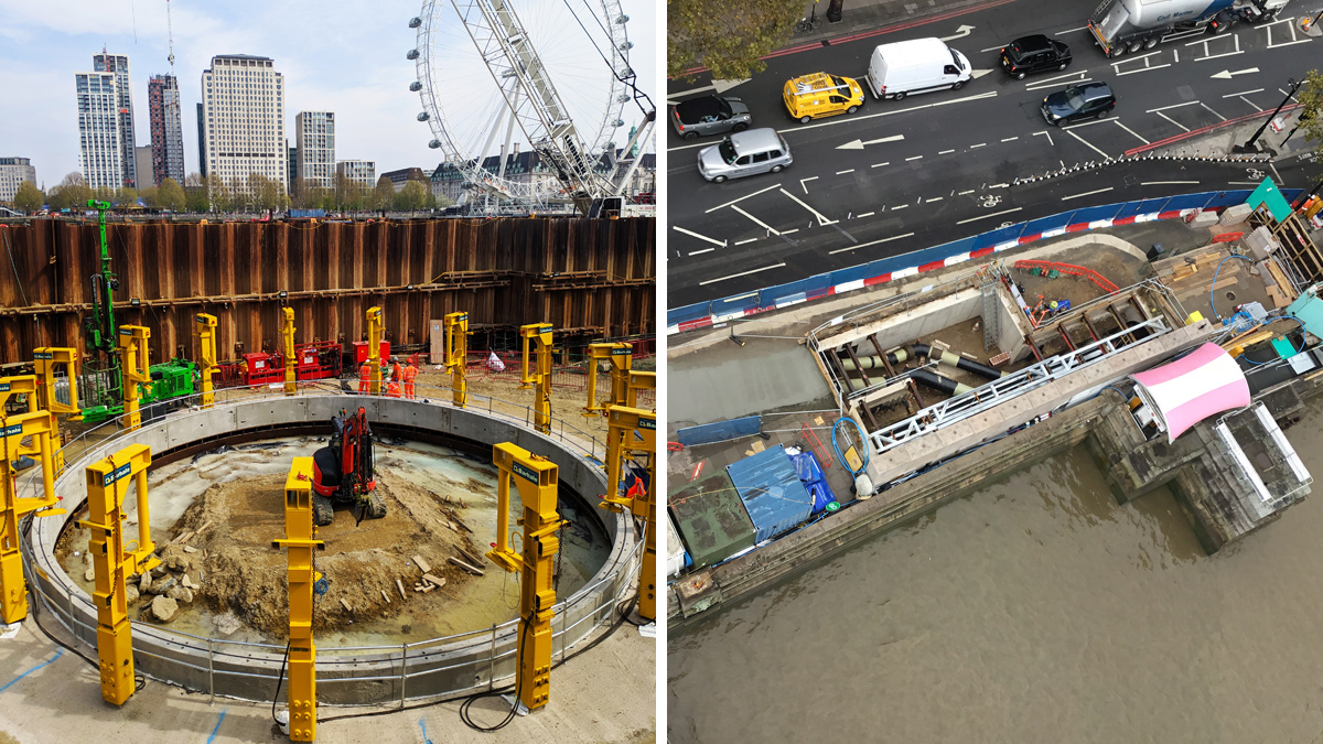
The next stage of the works comprised the diversion of the existing gas mains and the completion of the cofferdam. Once these were completed, piling operations could start. In total, 117 piles were installed: 47 (No.) 600mm bearing piles for the CSO structure and 70 (No.) 1200mm piles for the new river wall. These were required to provide adequate bearing capacity for the future structures.
The groundwater levels along the Tideway Central route, including Victoria Embankment, did not allow safe excavation of the shafts and tunnels and required the project team’s attention. A temporary works assessment was carried out along the route and verified by using pump tests, which modelled the required pumping capacity to dewater the existing aquifers.
At Victoria Embankment, Barhale installed four 106m deep Chalk Wells, six 65m deep Thanet Sand Wells, and six 50m deep Lambeth Group Wells. This system was also accompanied by in-shaft and tunnel wells that have targeted local pockets of water.
The 15m diameter shaft was built using three techniques. For the first 14m, the shaft was sunk using the caisson method and precast segments. This method was chosen for this section due to the granular material that was reported in the existing boreholes.

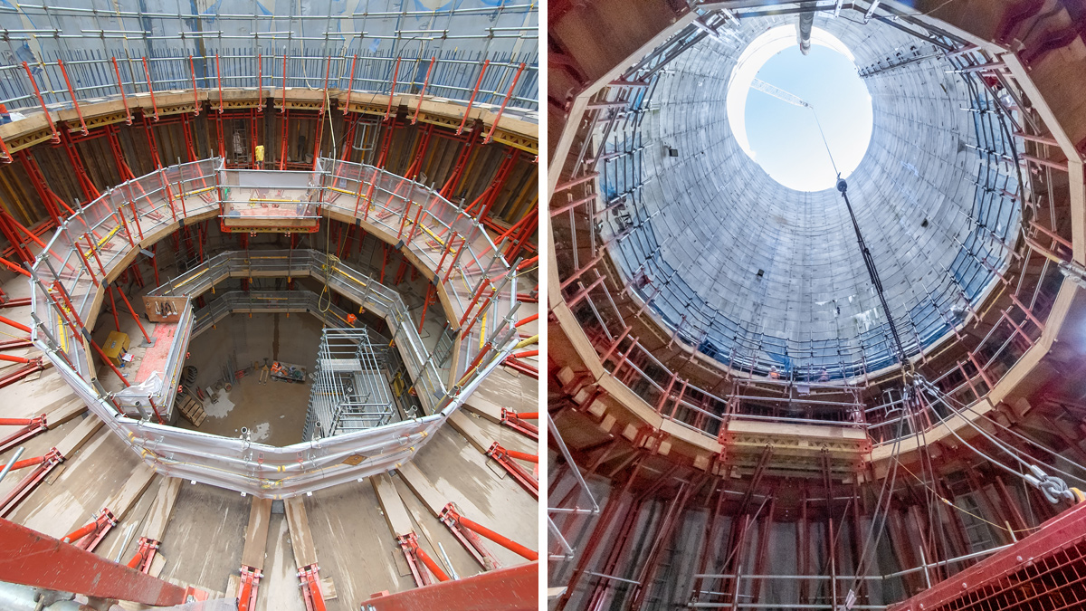
Secondary lining works – Courtesy of Barhale
Once past this layer, London Clay was encountered, and the excavation method was changed to underpinning. This method was used for excavating down to 32m below ground level. Due to the limitations of precast segments, the lining technology was changed to sprayed steel fibre reinforced concrete with a thickness of 600mm. This method allowed for better control of shaft profiles and portals for future works.
At formation level, a 2m deep reinforced concrete base slab was cast. The construction of this base slab required approximately 80 tonnes of steel and over 450m3 of high GGBS (ground granulated blast-furnace slag) concrete.
From this level a series of temporary works were implemented to allow the short connection tunnel to be excavated and supported using SCL (sprayed concrete lining). The connection tunnel is 18m long and varied in shape. During the first 14m, the tunnel internal diameter (ID) is 3.6m and in the last 4.5m the tunnel transitions to an ID of 4.9m.
The completion of the SCL works allowed for the site to transition to the full civils stage and start the works on the shaft and tunnel secondary lining and internal structures. Above ground level works that were released by the achievement of this milestone comprised the construction of new chambers that will deal with the intercepted flow and the new river wall that encompasses these structures and protects them from possible ship impact.
For these works at Victoria Embankment, Barhale used approximately 1400T of rebar and over 7000m3 of low carbon emission concrete, making this one of the bigger schemes that has been delivered during the Thames Tideway Tunnel project.
Tideway Central: Victoria Embankment: Supply Chain – key participants
- Main designer & contractor: FLO JV
- Ferrovial
- Laing O’Rourke
- Delivery contractor: Barhale
- RC piling: Expanded Piling
- Dewatering: WJ Groundwater
- Civils works: Flatley Construction
- Sawcutting/drilling: EDD (Euro Diamond Drilling) Ltd
- Waterproofing: Renesco
- Temporary electrical set-up: Select Site Solutions
- Concrete supplier: CEMEX UK
- Concrete supplier: Hanson UK
- Additives for SCL works: Normet
- Waterproofing: Sika
- Steel supplier: Express Reinforcements Ltd
- Steel supplier: HY-TEN Ltd
- Plant supplier: Select Cranes
- Plant supplier: Flannery Plant Hire
- Flow controls: AFFCO Flow Control (UK) Ltd
Challenging tunnel construction
The short connection tunnel at Victoria Embankment was design to be excavated and supported using the sprayed concrete lining method. This allowed for the short connection tunnel to wrap around and support the main tunnel during the break-out and final connection operation.
To put this in stages, the Victoria Embankment team was required to construct the tunnel using SCL and line the asset using cast in situ reinforced concrete and reduce its diameter to a constant 3m ID. The main tunnel team would be required to build the main tunnel using a segmental lining and cast in situ a reinforced liner, missing only the break-out area towards the Barhale connection tunnel. Once the segments were broken out, the two independent concrete structures would be joined together using cast in situ reinforced concrete.
The ground condition investigations for the connection tunnel identified a band of sand in the middle of the tunnel excavation, with a thickness of 1m and the presence of water.
On the assumption of the layer thickness and presence of water, a temporary design was progressed to support the excavation while spraying concrete. The designer prescribed the use of a pipe arch canopy support system for the narrower, 3.6m ID section of tunnel, with piles providing support for the remaining 4.9m ID section. The dewatering specialist prescribed the use of shaft wells and in-tunnel wells to allow efficient dewatering of the layer.

(left) Commencement of shaft works, and (right) diversion works within Victoria Embankment -Courtesy of Barhale
During the initial 3 to 4m of tunnel excavation, the face log showed an increase of the sand layer band and larger volumes of water than expected.
The sand layer covered approximately half of the excavation face at this point. As works progressed through the next 4m, additional wells continued to be drilled into the tunnel to target the water presence and the band of sand kept extending. Nine meters in, and the sand layer presence ranged from midway up to, and 3m above, the tunnel crown.
The encountered sand layer was also very fine which made spraying concrete challenging. As the concrete was sprayed, the sand bond was so small that the sprayed concrete was pilling off in small increments, making the excavation bigger. To prevent this occurrence, fast setting grout was sprayed as an initial layer and only then sprayed concrete.
This amendment to the plan did not solve the issue of the water presence and problems wet sand causes to excavations, especially tunnels.
An additional amendment to the plan had to be made. The team set out to space proof and conducted a feasibility study to understand if banker bars could be deployed. The temporary works design was then independently checked by a second design consulting company and approved by client FLO JV.
Barhale safely implemented the temporary works support, which meant installing eight advances of banker bars and spraying the primary concrete lining against them.
Works completion
The complex civils works on Victoria Embankment CSO Project to intercept the combined sewer overflows and to divert them into the Thames Tideway Tunnel presented challenging and unexpected ground conditions. Demonstrating agility and innovation, the Barhale team was able to deliver an excellent solution which both met the project timeline and provided best value for money.


