
Vyrnwy Aqueduct Modernisation Programme (2026)
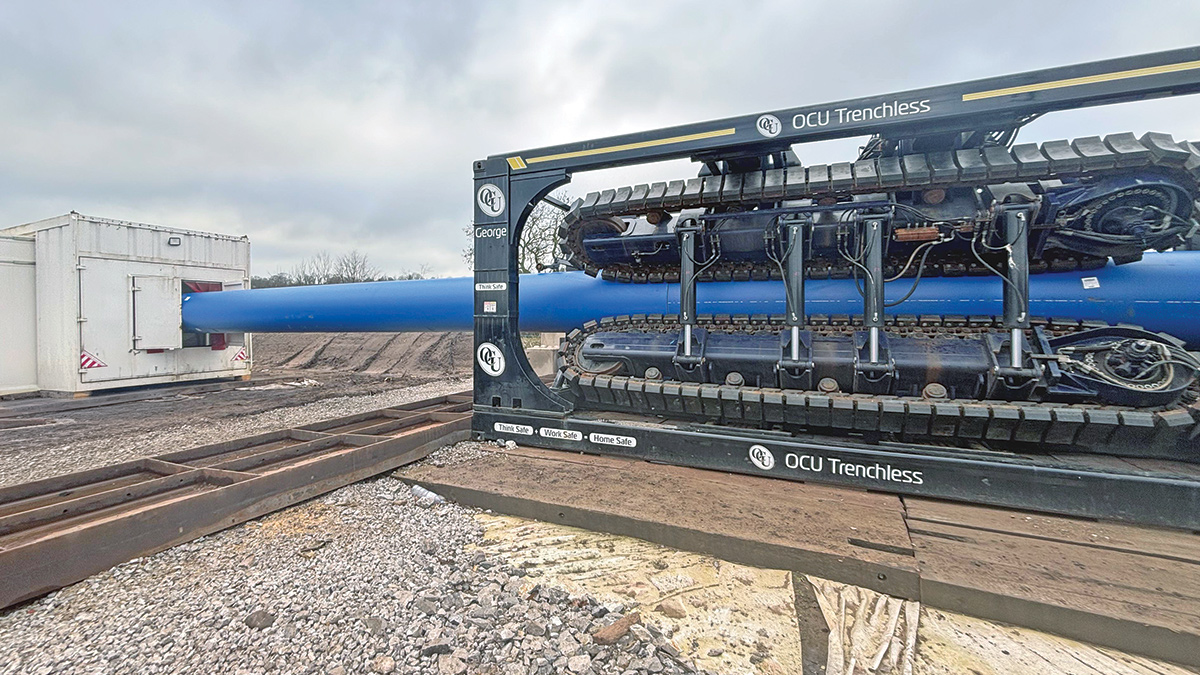
OCU Trenchless pipe pusher ‘George’ with blue PE liner pipe passing through its tracked clamping units - Courtesy of Waterco Datrys
The Vyrnwy Aqueduct is critical infrastructure, supplying potable water to approximately seven million customers across the North West of England. As a strategic asset within United Utilities’ network, its continued performance is essential to maintaining regional water resilience. Comprising three parallel aqueduct lines, the asset forms a key part of United Utilities’ strategic water supply network. As part of the Vyrnwy Aqueduct Modernisation Programme (VAMP), two of the cast-iron (CI) aqueducts are being rehabilitated by sliplining, while the third steel (ST) aqueduct is being cleaned and returned to service. The programme, which includes cleaning, rehabilitation and targeted upgrades, is designed to extend asset life while maintaining the operational continuity of these ageing, large-diameter pipelines.
Project drivers & scope
The primary driver for the scheme was to improve water quality within the Vyrnwy Aqueduct system and maintain a resilient, high quality potable water supply for customers across the North West of England. Replacement of the asset was not feasible due to spatial constraints, cost and operational risk, making rehabilitation the preferred solution.
A key component of the works was the installation of polyethylene (PE) liners using sliplining and pipe insertion techniques. Waterco Datrys was commissioned to undertake the civil and structural design for these works, with particular emphasis on designing thrust restraint systems to manage operational loads.
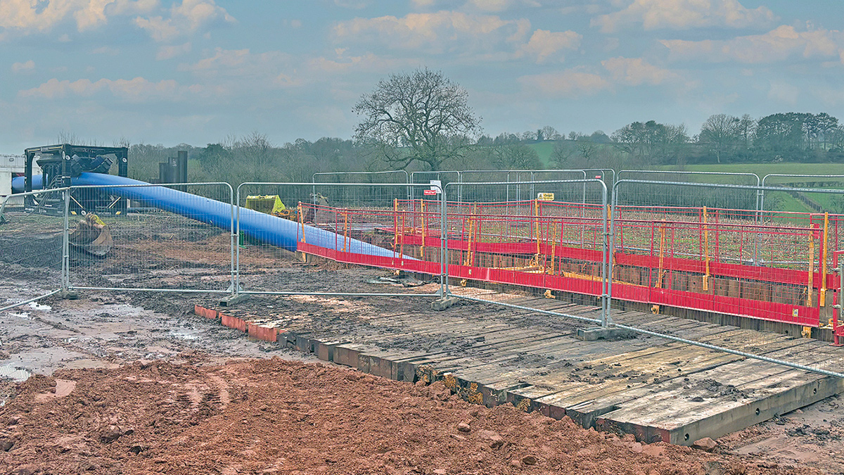
Launch pit with edge protection and PE liner string advancing from the pipe pusher – Courtesy of Waterco Datrys
Sliplining with PE pipe offers significant advantages, including improved corrosion resistance, a reduced installation footprint and enhanced hydraulic performance. However, the introduction of PE fundamentally alters the mechanical behaviour of the pipeline system.
Unlike traditional metallic pipes, PE exhibits viscoelastic behaviour. Under internal pressure, it expands radially and contracts longitudinally, generating significant axial forces at interfaces with rigid connections and fittings. Calculations indicated axial contraction forces of up to 64 tonnes, with combined thrust forces of up to 96 tonnes during installation and operation.
These forces presented a key engineering challenge, particularly where the upgraded system interfaces with existing cast iron pipelines within confined corridors containing multiple live assets.
Design approach
A holistic design approach was adopted, integrating structural, geotechnical and construction considerations into a unified solution. Thrust block designs were developed to suit varying pressure and ground conditions, incorporating standalone reinforced concrete blocks, reinforced concrete blocks encasing sheet piles where additional resistance was required, and reinforced concrete blocks combined with steel frame arrangements to transfer part of the load into the existing pipe. The design was undertaken in accordance with Eurocode 2 and Eurocode 3, supplemented by CIRIA guidance and United Utilities’ CESWI standards. Particular attention was given to ensuring a continuous and reliable load path throughout all stages of construction and into long-term operation.
Constructability was a primary design driver, with solutions developed to be deliverable within confined working areas while maintaining safety and minimising interaction with existing infrastructure.
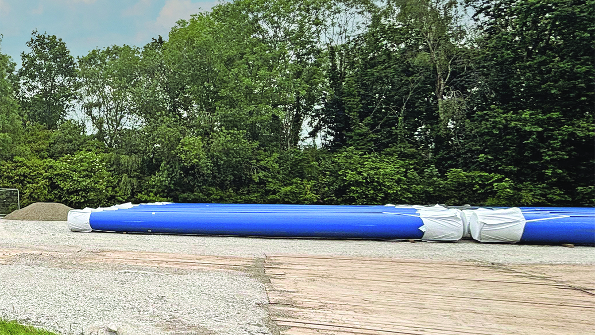
Blue PE liner pipe strings stored ahead of installation – Courtesy of Waterco Datrys
VAMP: Supply chain – key participants
- Principal contractor: OCU Group
- Civil & structural design: Waterco Datrys
- Temporary works: GroundShore Ltd
- Pipe pusher supplier (“George”): OCU Group
- Mechanical couplings supplier: Victaulic
- Mechanical couplings supplier: Viking Johnson
- PE pipework supply: Radius Systems
- PE pipework supply: Aliaxis
- Steel pipework supply: Valmech, an OCU Group company
- Nova Spira fittings for cast iron connections: R2M Limited
Permanent works: Thrust blocks
The permanent thrust restraint system comprises reinforced concrete base slabs, upstands and shear keys designed to resist axial pipeline forces. The system provides resistance through a combination of structural capacity, interface friction and passive ground pressure.
Axial forces generated by the pipeline are transferred through the concrete upstand and distributed into the base slab, where resistance is provided by the slab’s self-weight and friction with the underlying soils. The shear key mobilises passive resistance within the surrounding ground, significantly increasing sliding resistance.
Ground conditions were characterised as loose to medium-dense sands, soft clays and firm to stiff clays. The designs developed accounted for temporary excavation conditions and long-term backfill scenarios. Stability analyses confirmed acceptable factors of safety against sliding and overturning under all loading conditions.
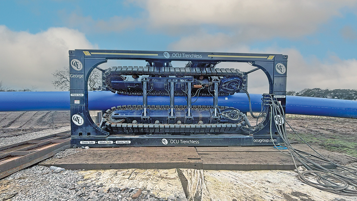
Pipe pusher ‘George’ tracked clamping units – Courtesy of Waterco Datrys
Construction methodology & sequencing
Construction was centred on launch and reception pits designed to facilitate the insertion of PE liners into the host pipeline. Pipe strings were assembled in sections and advanced using specialist pipe-pushing equipment.
The installation process required careful control of alignment, friction and lubrication to ensure smooth insertion and prevent excessive loading. Launch pits served as critical control points, where restraint systems were required to manage both temporary and permanent forces.
Typical sequencing involved excavation, installation of temporary works, deployment of steel thrust frames, pipe insertion, installation of permanent connections, and construction of final thrust blocks. This staged approach ensured that all loads were safely managed throughout the construction process.
Temporary works integration & risk management
Temporary works were designed as an integral part of the overall structural solution. The thrust frame system prevented unintended load transfer into existing assets and provided stability during pipe preparation and installation.
Anchorage design ensured loads were effectively transferred into supporting slabs, with adequate embedment and spacing to resist pull-out forces. The system was also designed for ease of installation and removal, supporting efficient delivery within constrained working conditions.
Risk mitigation measures included independent end restraint systems, strict sequencing controls, and close coordination with the contractor to manage installation tolerances and site conditions.
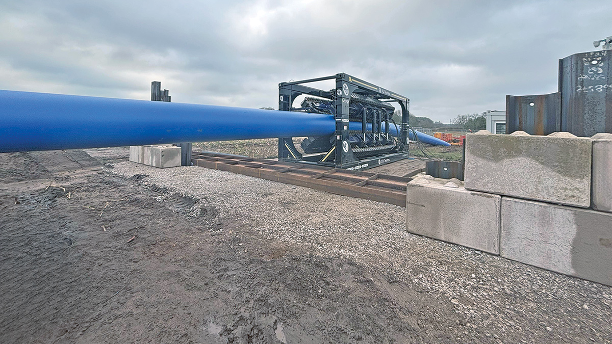
Pipe pusher ‘George’ on steel base frame beside concrete blocks – Courtesy of Waterco Datrys
Materials & pipeline interfaces
A key challenge was managing interfaces between different pipeline materials, including cast iron, steel and polyethylene, each exhibiting distinct behaviour.
Flexible couplings and flange adaptors were used to accommodate differential movement and provide installation tolerance. Design solutions ensured that axial loads were not transferred into legacy assets, protecting the integrity of existing infrastructure. These interface details were critical to ensuring long-term system performance and operability.
Construction considerations
The works involved deep excavations supported by sheet piling systems, with temporary bracing where required. Groundwater management was necessary to maintain safe and stable working conditions.
Confined space working, restricted access, and proximity to live infrastructure required detailed planning and coordination. Several critical assets, including the Manchester Jet Line, were located close to the works, necessitating careful design development and construction planning to maintain operational integrity and minimise risks to existing infrastructure. Construction activities were carefully sequenced to minimise disruption and ensure the safety of operatives and assets.
Particular attention was paid to preventing load transfer into existing cast iron pipelines, with dedicated restraint systems ensuring that legacy infrastructure was not overstressed during construction or operation. In some locations, the existing lined pipeline formed part of the restraint system, working alongside new restraint measures to distribute thrust forces and maintain the aqueduct’s integrity.
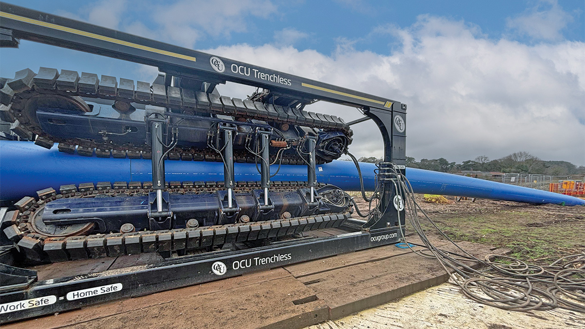
Pipe pusher ‘George’ and its hydraulic hoses, with the PE liner pipe – Courtesy of Waterco Datrys
Innovations & key outcomes
The project demonstrated the benefits of integrating temporary and permanent restraint systems within a single design framework. This approach improved safety, reduced construction risk and ensured continuity of structural performance.
Explicit modelling of PE pipe behaviour, including axial contraction and radial expansion, enabled more accurate force prediction and more robust design solutions. The scheme also highlighted the importance of collaboration between designers, contractors and suppliers in delivering complex infrastructure upgrades within constrained environments.
The resulting design offers a repeatable approach for future rehabilitation schemes involving large-diameter pipelines and modern liner materials.
Conclusion
The Vyrnwy Aqueduct Modernisation Programme represents a significant investment in the resilience of a critical water asset. The successful design and implementation of thrust restraint systems have enabled the safe installation of PE liners while maintaining the integrity of existing infrastructure.
The approach demonstrates the value of integrating structural, geotechnical and construction considerations, delivering a robust and transferable solution for future pipeline rehabilitation projects.