Wetherby STW (2016)
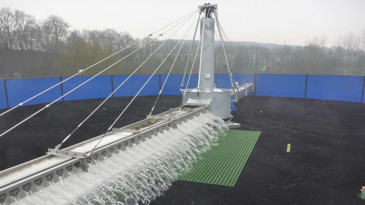
Tertiary nitrifying trickling filter (TNTF) full scale trial.
Wetherby STW is the wastewater treatment facility for the market town of Wetherby and its surrounding area. It has a population of approximately 23,000 people and is mainly unaffected by seasonal variations other than the local Wetherby Race Course. As there is no direct connection from the racecourse to the sewage treatment works, all racecourse wastewater is transported locally by tankers. The plant has been developed over many years and its present operation is a combination of the existing works and its subsequent refurbishment/enlargement in order to meet the growing community.
Current operation of the sewage treatment works
The inlet flow enters a screw pump chamber where all of the plant flow is lifted by the inlet screws and passed forward through the inlet screens and grit removal system. The inlet flow is monitored at this point via a channel flow meter.
Flows enters a primary tank splitter chamber where it is split equally through 2 (No.) primary settlement tanks (PSTs). The outlet flow of the PSTs then combines back together and enters the carbonaceous only activated sludge plant (ASP) splitter chamber. It is then equally split and enters the 2 (No.) lanes/4 (No.) pockets of the ASP (surface aeration system). The outlet channels of the ASP combine together and enter the final settlement tank (FST) splitter chamber.
The plant flow is then split equally through the 2 (No.) FSTs and is then passed forward onto the tertiary nitrifying mineral filters splitter chamber which splits the flow into 4 (No.)mineral filters prior to combining again. The flow is again split and passes through 2 (No.) humus tanks. The effluent then finally enters the River Wharfe at the bottom of the site.
Outline brief of requirement
aBV, a joint vernture between Amey and Black & Veatch (now Binnies) was engaged by Yorkshire Water (YW) to investigate, design, construct and commission a tertiary nitrifying trickling filter (TNTF) system which was to be utilised by YW as part of the national trial for the chemical investigation programme (CIP2).
Initially the design brief was to work with the full site flows which gave a flow to full treatment (FFT) of 128l/s. The design parameters were validated by a period of flow and load sampling which was undertaken by 24 hour composite samples. The loading was agreed with YW and comprises of:
- Suspended Solids: 165kg/day
- BOD5: 100kg/day
- COD: 480kg/d
- Ammoniacal-N: 280kg/d
- Alkalinity (minimum): 1435kg/day
The outlet treated effluent quality from the new TNTF had a design restriction of Ammoniacal-N 15mg.
The project was further challenged as its main intention is that it would only be required to operate for the life cycle of the trial programme of 12 months, this gave the project team opportunity to revise the required scope in order reduce the target value further. This was successfully undertaken jointly by aBV, sub-contractors and client.
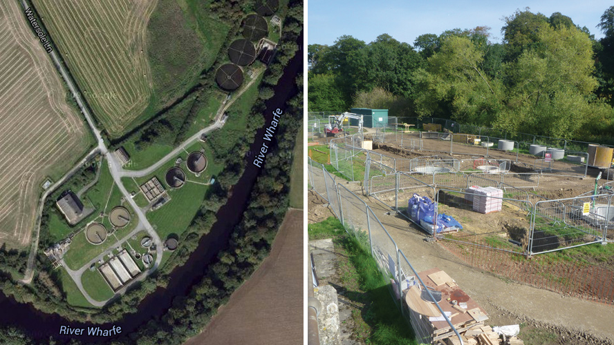
(left) Wetherby STW and (right) Ongoing civils works – Courtesy of aBV
Design decisions
Following high level costing of the solution it was identified that the proposal was unaffordable by Yorkshire Water. As a result of this affordability challenge, Yorkshire Water instructed aBV to develop alternative solutions to that identified in the Early Contractor Involvement (ECI) report submission. Three alternative options were identified:
- A 2-tank option to treat 100% of the works flow to full treatment (FFT).
- A 2-tank option to treat 50% of the works FFT.
- A 1-tank option to treat 50% of the works FFT.
A scope and cost assessment of the 3 options showed that the only option that could be provided within the Yorkshire Water budget for the scheme was the single tank option to treat 50% (64l/s) of the works flow to full treatment.
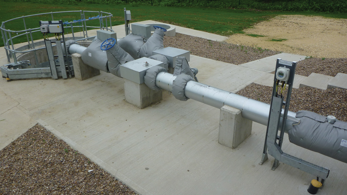
TNTF pumping station – Courtesy of aBV
Final design progressed
The new plastic media tertiary nitrifying trickling filter (TNTF) plant was installed between the final settlement tank outlet and the tertiary mineral filter inlet. 50% of the plant flow was diverted into a new TNTF wet well via a low level splitter chamber. Treated effluent from the TNTF re-joins with the remaining 50% of the plant flow and directed to the existing mineral filters.
A duty/standby pumping system pumps a constant flow up into the TNTF at a rate of 83l/s, the minimum wetting rates for this system. 50% FFT is 64l/s; however the hydraulically controlled recirculation system ensures the TNTF outlet flows compensate the shortfall in flow to ensure a constant flow of 83l/s is conveyed onto the TNTF. The flow to the TNTF can be manually adjusted within the pump range but this was outside of the requirement of the scheme.
Ammonia concentrations in the feed and discharge to the TNTF are continuously measured by permanently installed in-line fixed instruments.
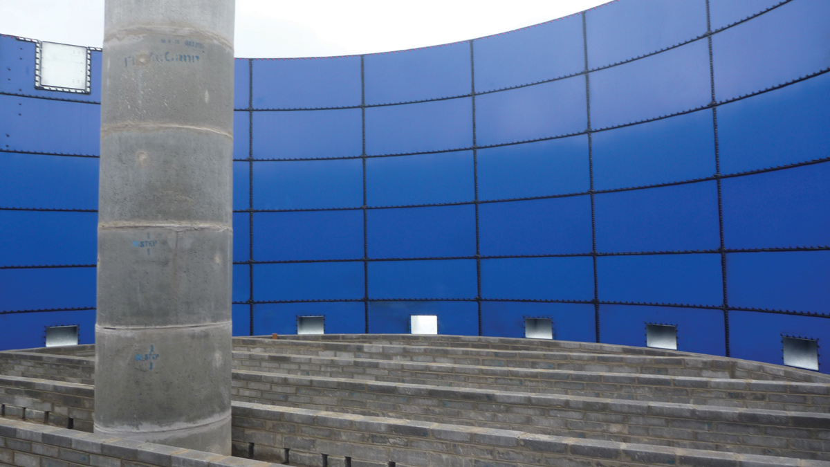
TNTF internal view – Courtesy of aBV
Process design parameters
The incoming flow design parameters are stipulated in the table below and formed the basis of the process guarantee. Feed BOD, COD and suspended solids loads to the TNTF are the 95%ile values obtained from a 9 day sampling programme undertaken in November 2014.
Concentrations were calculated at average daily flow (ADF). Design based on treated ammonia effluent (discharge from TNTF process) requirement of 15mg/l (95%ile).
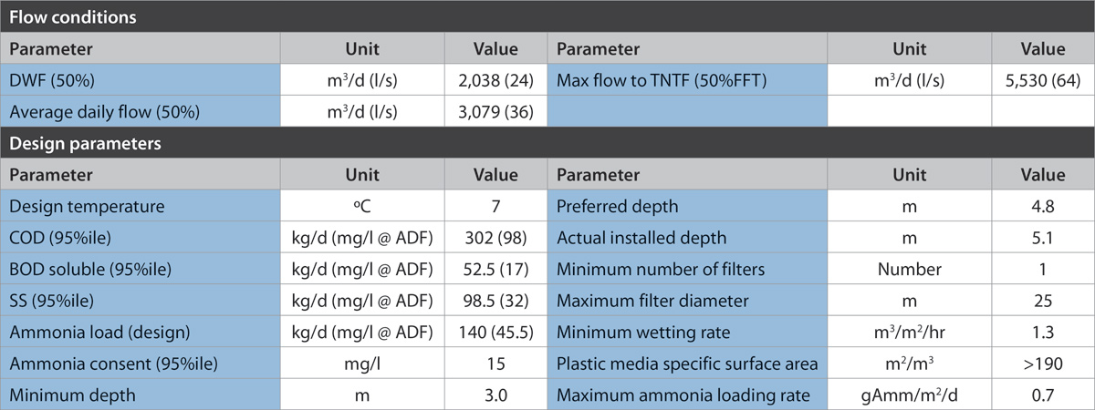
Flow conditions and design parameters
Design conditions also included sufficient alkalinity in the feed to drive nitrification and the absence of any biological inhibitors present in the influent. The TNTF was designed to tolerate a 50% variation in load from day to day (within the maximum design load) providing that the plant has seen the higher loading on 3 consecutive days in the previous 7 days.
Building the design – pre-construction works
Due to the proximity of the works to the local river extensive ecological surveys were undertaken. They identified the presence of otters, badgers, newts and ground nesting birds. As such, the works were programmed to be sympathetic to the environment and anyone working on the site was given the relevant ecological tool box talks.
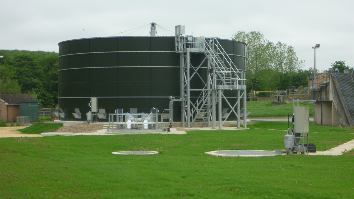
TNTF plant – Courtesy of aBV
The contract award date was 8 June 2015 with detail design commencing immediately. The design was agreed on 25 August 2015; however due to time constraints it was agreed that construction works commenced prior to this as the collaborative service team (CST) had already agreed the initial phase of works. Site works commenced therefore on 13 July 2015 with all sub-contractors having been informed of the required delivery dates and timescales associated for the site works. All the works were delivered to a high standard and with minimal delay. Below is an indication of the activities and performance of the works:
- 08/06/2015: Contract award
- 25/08/2015: Completion of detailed design
- 13/07/2015: Site set up commence:
- 30/07/2015: Commence civil construction
- 04/11/2015: TNTF S/C completion
- 13/10/2015: Mechanical installation complete
- 04/11/2015: MCC installation
- 30/10/2015: Electrical installation
- 17/12/2015: Commissioning completion
- 18/01/2016: Reliability completion
It should also be noted that there was no lost time incidents on site.
Testing conditions
The design is based on treated ammonia requirement of 15mg/l (95%ile). The performance test period was based on a 24 hour composite sample over a 14 day consecutive day period. The 95%ile was measured by the allowance of 0 failures from the 14 samples. Subject to the design basis and 50% variation in load criteria being met, if the TNTF effluent fails to meet the target ammonia concentration due to the influent load exceeding the design criteria, that day’s sample was discounted and an additional day in lieu would be added to the testing period.
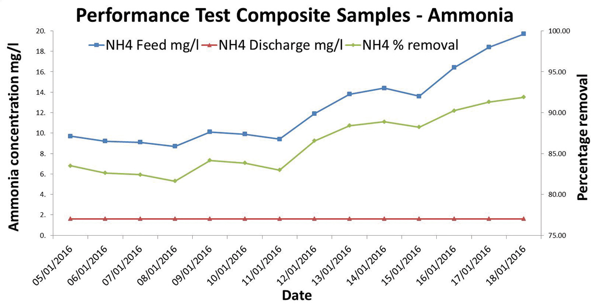
(Note: due to limitations in analysis to 1.6mg/l at the external laboratory, the actual value for the effluent was lower than shown.)
The main target date for the contract was set as the TNTF to have been commissioned and in service for early November to allow sufficient time for the biological seeding of the system. This was achieved by turning flows onto the TNTF on the 6 November and an allowance of 63 days included so that it would achieve the design parameters when the external sampling commenced in March 2016. This was achieved and proved in January by completion of the 14 day process reliability. Above is a graph indicating the removal of ammonia across the Wetherby STW tertiary nitrifying trickling filter.
Wetherby STW – Tertiary nitrifying trickling filter: Supply chain
- Designer: aBV (amey-Black & Veatch)
- Trace heating & insulation: Tees Insulation
- Designer: LEADA
- Access metal works: Jardonich
- Designer: GHD
- FRC contractor: BBC Formwork
- Civils contractor: aBV
- Lifting equipment: Peter Cassidy
- Mechanical installation: aBV
- Kiosk: MCL Group Industries
- TNTF plant: ENEXIO 2H Water Technologies
- Steel tank: Kirk Environmental
- Electrical installation: Circle Control & Design Systems
- Systems valves: Industrial Valves
- MCC & kiosk: Total Automation & Power
- Pump suppliers: Xylem Water Solutions
- Distribution arms: Sewaco Ltd
- Ductile pipework: Electro Steel
- Drive controls: Drive Systems Ltd
- Stop boards: Hambaker Adams


