
King’s Scholars’ Pond Sewer (2018)
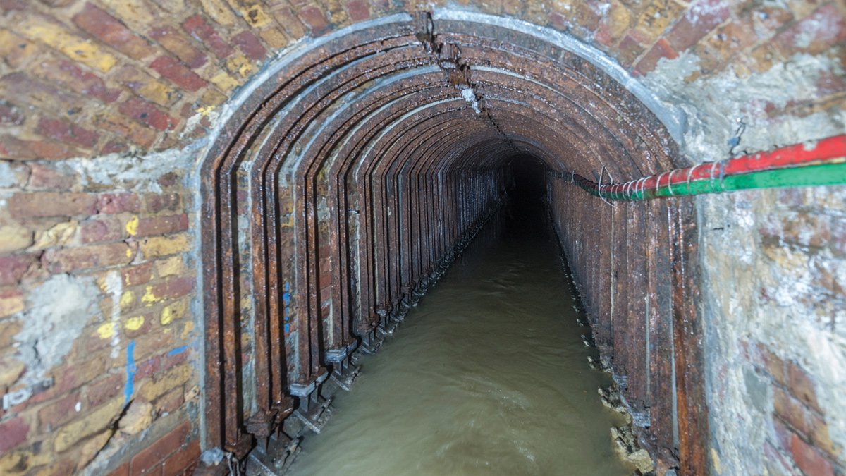
Internal shot of the section of sewer to be remediated - Courtesy of eight2O, SMB-JV
There was evidence of significant internal degradation and deterioration of the King’s Scholars’ Pond Sewer in the vicinity of the Baker Street tube station London Underground tunnel. Degradation included significant cracking of the sewer brickwork as a consequence of considerable settlement of the LUL railway tunnel beneath. The sewer is situated beneath a key artery road into central London and above the London Underground railway lines, this renders any form of top down or bottom up solution particularly difficult and extremely costly. At this location the sewer is supported by two primary cast iron beams, which span between pad-stones embedded within the brick wall of the railway tunnel. Between these two primary beams are profiled cast iron invert plates connected back to the beams via bolted connections. A brick crown completes the sewer profile.
Design options
At an early stage it was identified the preferred option for remediation was internal and thus the design approach followed possible solutions which could be constructed from within. Initial solutions involved the development of a carbon fibre modular liner which would transfer load from the brick crown through the invert plate of the sewer and onto support beams spanning between the cast iron beams. The team also explored the use of a U-shaped trough, designed to span the length of the tunnel beneath.
The PR14 business plan solution was based on replacing the existing cast iron beams and strengthening the London Underground walls. It was calculated three months’ worth of train possessions would be required with an approximate cost of £30m. A further £7m would be required to complete the civils works.
Other considerations included the use of vertical anchors to make use of the concrete and reinforced concrete slabs installed in the sub-surface above the sewer (believed to have been placed during World War 2). The solution was to ‘hang’ a lining solution from the roof, thereby negating the need to carry out any additional support work from within the London Underground. Unfortunately, ground investigation work carried out yielded unsatisfactory results as to the structural integrity of the concrete/reinforced concrete slabs.
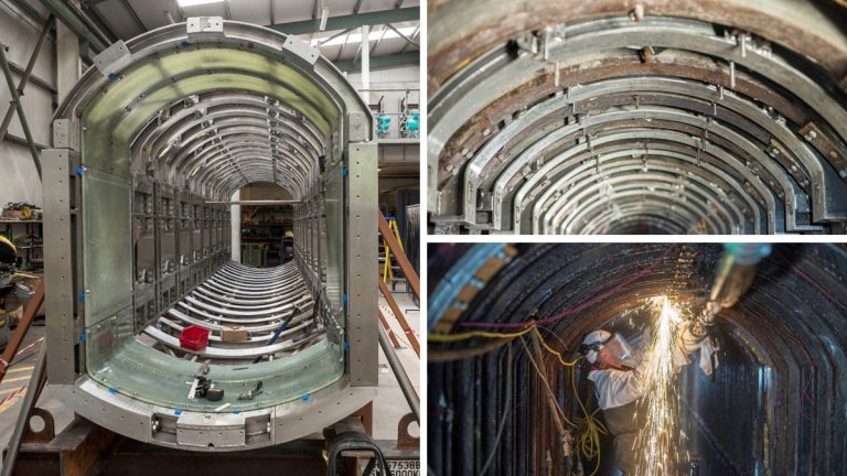
The business case recommendation was the construction of a modular duplex steel (grade 1.4462) Vierendeel truss with an associated glass fibre reinforced plastic (GFRP) liner. Designed to be carried through the aperture of an existing manhole, and once in situ, bolted together to form a permanent bridge which spans beyond the London Underground tunnel beneath it.
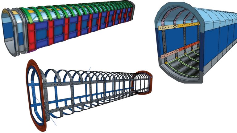
(top left) Duplex steel Vierendeel truss (bottom left left) inner cage and (right) liner assembly – Courtesy of eight2O, SMB-JV
Outline specification
- 120-year life span for the steel, without any major maintenance or replacement.
- 50-year life span for theliner, without any major maintenance or replacement.
- A modular construction, which can be carried through a 600mm x 750mm access manhole.
- A watertight structure capable of withstanding a nominal pressure up to 0.3bar.
- Ability to accommodate minor settlement of the global structure with a maximum of 15mm differential settlement.
- Liner assembly no more than 35kg per single component to allow for single manhandling during any future maintenance requirements.
- Steel truss global tolerance +/- 1mm, liner assembly tolerance +/- 2mm.
Design for the future
During initial investigations it was evident that the concrete deck system could not be relied upon in the future and there was no reliable method to confirm the percentage of load that is being attracted to the London Underground tunnel and or the sewer arch where they intersect. Therefore, the design approach was to account for all load cases which took into account all permanent loads (sub-surface) and all the variable loads (traffic loads) which totalled 200 tonne.
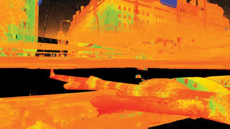
Snapshot from laser scan – Courtesy of eight2O, SMB-JV
Digital delivery
Laser scanning of the existing asset enabled the team to design and visualise concepts in context with the wellbeing of construction teams in mind.
Geo-referenced 3D models allowed the team to place its model within the laser scan to measure clearances and develop solutions in locations where access to bolts and joints would be difficult by hand.
BIM models and fly through videos were utilised to train the site team in the construction sequence and the potential challenges they would face during the build.
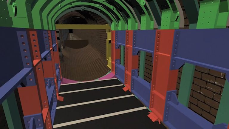
Snapshot from construction sequence – Courtesy of eight2O, SMB-JV
Off-site manufacture
Due to the long lead time on duplex stainless steel, the order for the steel was placed ahead of the GFRP liner. This gave the project team the opportunity to carry out various off-site assembly tests with site teams prior to the delivery of the liner.
The liner was fabricated by a specialist composite manufacturer in Poland, water tests and gasket testing over several weeks took place to ensure the structure was water tight.
Site works
Enabling works consisted of the following:
- Installation of flow control and flow monitoring systems upstream of the worksite to allow sufficient time for evacuation in the event of a flood.
- Installation of structural monitoring systems both within the sewer and the CI girders within London Underground tunnel to highlight any movement during temporary states of construction.
- Installation of cabling and ducting below the pedestrian crossing eliminating risk of public interface with site services between site compounds.
- Render removal and brick work repair within the sewer to strengthen and extend asset life of existing brick soffit arch.
- Systematic replacement of 48 existing PFC ribs with the new slim line temporary works straps which would allow additional work space.
- Installation of the cast iron invert protection plate and temporary decking to provide a flat platform to work from.
- Installation of the temporary jacking beams and bracing which will be used to brace the steel truss when in construction. This is important as in live conditions the steel bridge needs to be fixed into place in case the sewer surcharges and requires evacuation.
- Brickwork sampling of the London Underground tunnel walls.
- Brickwork coring and grouting of the London Underground tunnel walls.
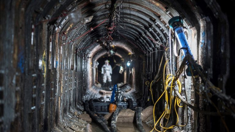
(Left and top right) Arches pinned to the roof (main works) and (bottom right) cutting out PFC ribs – Courtesy of eight2O, SMB-JV
Main works
The main works started in June 2018 and is expected to finish in October 2018:
- Installation of the duplex steel Vierendeel truss which will support the sewer for the next 120 years.
- Installation of the glass fibre reinforced liner panels which will transfer water load through the section of the steel truss.
- Installation of the rings (end pieces) constructed of GFRP and duplex steel channels which will funnel the parent sewer flow.
- Installation of a hand rail to aid future inspections.
- Re-profiling of the sewer i.e. providing slight fall which will ensure flow continues to pass downstream.
- Removal of the temporary works straps, platform, invert protection plate and jacking beam supports once the top members of the truss have been grouted into position.
- Reinstatement of the existing services in the sewer.
- Removal of all flow monitoring, control systems and structural monitoring in place during the construction works.
- Further three months structural monitoring will continue once complete to ensure a baseline to record future movement is obtained.
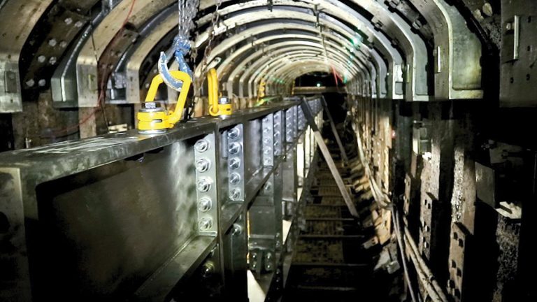
Close up of girders (main works) – Courtesy of eight2O, SMB-JV
Space issues
A lack of overall work space resulting in a different construction sequence than that used during the fabrication of the components. This was mitigated by fitting dowels and reference points across the structure which would only allow for the components to be aligned as per the erected structure off-site.
Due to the lack of clearance between the side girders and temporary works straps, the arch beams had to be pinned between the slim line straps into the roof via a series of eye bolts which were drilled and fixed into the crown of the sewer.
Flow control
Management of live flows, local and storm. The role of a confined space manager (CSM) was developed to solely manage entry due to the unique circumstances on the project. To facilitate and provide suitable time frame for emergency evacuation the use of dam boards, depth gauges and cameras upstream of the work site on two connecting branches allowed the CSM teams to visually monitor flows throughout the works.
Installation of slim line temporary works straps – Courtesy of eight2O, SMB-JV
Lifting operations
Lifting operations and manual handling assessments were key on management of risk. All lifts plans were developed by a competent rigging, slinging and signalling operative prior to being signed off by the appointed person.
The project completion is scheduled for November 2018. Considering the access constraints and design challenges, the installation of the duplex steel Vierendeel truss and associated GFRP liner has been deemed a resounding success. The complexity of the operation and the limited accessibility resulted in a bespoke, unconventional solution to a challenging project.
Conclusion
The principle designer and principle contractor for the scheme is the eight2O, SMB-JV (comprising Skanska, Stantec UK and Balfour Beatty). McAllister Group has been contracted as both a specialist designer to provide the liner design and as the installation supplier for the main works package.
The innovative approach being undertaken on this challenging project will save 26,443tCO2e carbon and £23m when compared to the AMP6 business plan solution. The new bridge will allow Thames Water continued use of the asset for a further 120 years without any major replacement of structural components and significantly reduce its asset risk on the sewerage network in London.