Lee Tunnel – Flow Transfer System (2016)
Mott MacDonald
Thames Water’s Lee Tunnel will create a cleaner, healthier River Thames by capturing combined sewer overflows at Abbey Mills Pumping Station, preventing 16 million tonnes of stormwater and sewage from being discharged into the River Lee each year. Up to 385,000m3 of stormwater and sewage will be stored in the 7km long tunnel and transferred to the Beckton STW, where it will be pumped out and treated. In future the Lee Tunnel will form the downstream section of the 25km long Thames Tideway Tunnel. This combined tunnel will capture an annual average of 39 million tonnes of stormwater and sewage from the 35 (No.) most polluting combined sewer overflows along the River Thames. The project required the construction of large elevated pipelines to transfer flow pumped out of the tunnel from the pumping shaft 400m across the operational Beckton STW site to the inlet works for treatment; this article details this section of the project.
Project background
In order to treat the stormwater and sewage captured in the Lee Tunnel, the scheme’s original reference design included a new wastewater treatment stream constructed on the existing Beckton Sewage Treatment Works site adjacent to the tunnel’s 80m deep pumping shaft.
This new treatment stream was later deleted when a review demonstrated that the recently upgraded sewage works would have sufficient capacity to treat the Lee Tunnel flows.
By this time however, the tunnel alignment and pumping shaft location had been fixed, making it necessary to transfer the flows from the pumping shaft to the existing Beckton inlet works, approximately 400m away, leading Thames Water to commission the Flow Transfer System.
The tender design was undertaken by the MVB Joint Venture, comprising Morgan Sindall, Vinci Construction Grands Projets and Bachy Soletanche with design services provided by Mott MacDonald.
The reference design for the Flow Transfer System was for a large diameter buried pipeline crossing the site. Flow pumped out of the tunnel to ground level would then be transferred across the site through an inverted syphon at rates up to 7.6m3/s; with a drain down pumping station used to empty the pipeline after use.
However an opportunity was identified whereby available head on the shaft’s pumps could be used to lift flows sufficiently high above ground level to transfer them across the site via an elevated gravity pipeline. This offered cost and operational benefits by removing the need for extensive earthworks on a congested operational site and eliminating a drain down pumping station (with its associated power use) since the pipeline could be free draining.
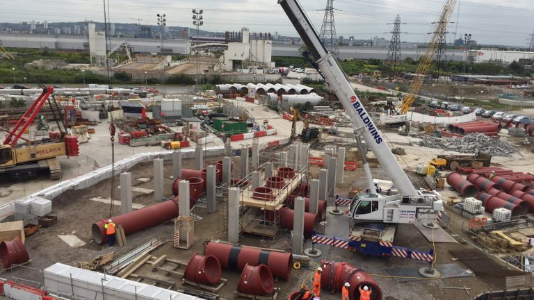
Installation of the delivery pipelines – Courtesy of MVB JV
The Flow Transfer System
Following acceptance of the proposal for the elevated solution, early in the detailed design phase it was decided to double the capacity of the Flow Transfer System to enable transfer of the full 15.3m3/s required for the future combined Lee Tunnel/Thames Tideway Tunnel from the start. This achieved significant cost savings and reduced operational impact compared to constructing a system initially for the Lee Tunnel and then enlarging it in future for the Tideway Tunnel. The final as-constructed Flow Transfer System comprises:
- 6 (No.) Ø 1.4m buried ductile iron delivery pipelines, each up to 150m long transferring flow from the pumping shaft to a collection chamber.
- An above ground concrete collection chamber (approximately 17.5m x 14.5m x 4m deep) where flows recombine.
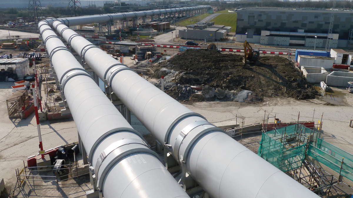
- Twin Ø 2.4m, 410m long steel transfer conduit pipelines supported up to 6m above ground level on steel towers to convey flow by gravity over the operational site from the collection chamber to the discharge chamber.
- A concrete discharge chamber (approximately 25m x 18m x 3m deep), located directly on top of the Victorian-built brick Northern Outfall Sewers immediately upstream of the existing inlet works. Here flow is split into five lanes before dropping into corresponding barrels of the existing sewers below.
In order to realise the benefits of moving to the above ground solution the design and construction had to overcome numerous challenges, including the hydraulics, connections into existing assets, and pipeline installation. These are described in more detail below.
Hydraulic challenges
The Flow Transfer System will convey flow rates ranging from 0.3m3/s to 15.3m3/s. This allows for the tunnel being pumped out at the maximum rate and for when smaller pumps are used to drain it down to the pumping shaft invert.
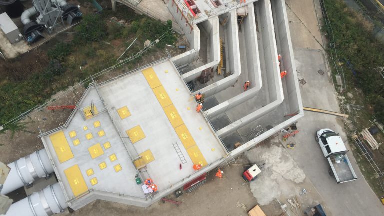
Discharge chamber during construction – Courtesy of MVB JV
The system has sufficient capacity to carry the full flow across the site by gravity, whilst also ensuring self-cleansing velocity is maintained at minimum flow. This is particularly important because the system will only be used intermittently to empty the tunnel, meaning any material deposited could dry out, turn septic or become odorous.
The hydraulics of the system had to work for the full range of flows, and within several constraints posed by the site, including:
- The maximum height the pumps could lift water from the pumping shaft 80m below ground at the upstream end.
- The levels of the existing sewer structure that the discharge chamber connects into at the downstream end.
- Providing sufficient clearance to both the main site access road that the transfer conduit pipelines pass over, and to the overhead high voltage powerlines they pass beneath.
These constraints defined a single vertical alignment for the conduit pipelines, and a maximum of one metre of fall along the pipelines to drive the flow.
Additionally, because of an operational need to ensure incoming flow remained balanced at the inlet works, the project brief required that the flow is equally split between the five channels of the discharge chamber to ±1%.
Hydraulic modelling was used to demonstrate these requirements would be achieved. Firstly, computational fluid dynamics (CFD) was used to confirm and refine the geometry of the chambers and size of the pipelines. The results of the CFD modelling then informed physical modelling of each chamber at 1:5 scale; and of the whole system, including all 410m of pipeline, at 1:14 scale. The physical modelling further refined the geometry and determined the baffle/benching arrangements required to achieve the flow split at the discharge chamber.
The modelling also demonstrated that a low flow channel insert in the pipeline would not be required. CFD modelling determined that self-cleansing velocity would be maintained even at the lowest flow rate and the physical model demonstrated that sedimentation would be insignificant. Removing this low flow channel led to cost savings during construction and eliminated future health & safety issues related to its inspection and maintenance within the pipelines.
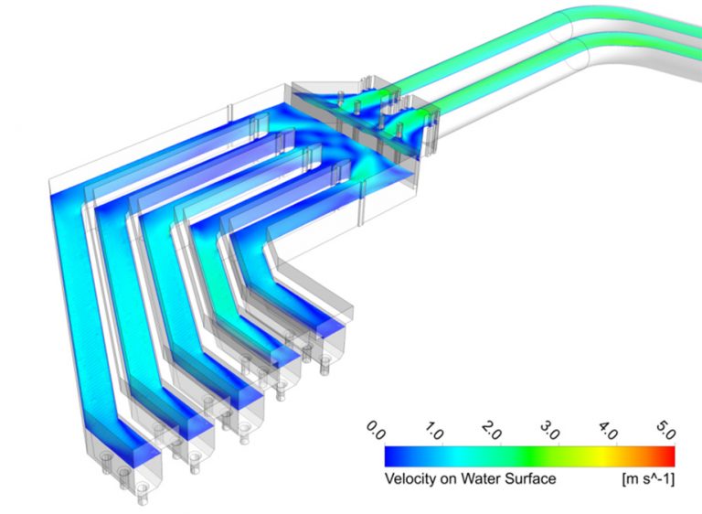
Computational fluid dynamic modelling of discharge chamber – Courtesy of Mott MacDonald
Connecting into the Northern Outfall Sewer
The 25m x 18m x 3m deep reinforced concrete discharge chamber at the downstream end of the Flow Transfer System was constructed directly on top of, and connected into, the five barrels of the existing Victorian-built brick Northern Outfall Sewers – a critical asset to London’s sewerage network and one that was of unproven structural condition.
Working on the Northern Outfall Sewer represented a significant project risk because construction involved breaking out an existing concrete road overlaying the brick sewers (exposing and unloading the top of the brick arches) to replace it with the significantly heavier discharge chamber; and the coring of 15 (No.) 700mm diameter holes through the crown of the brick sewer barrels that form the connections to the discharge chamber.
This risk was managed firstly by undertaking structural inspections inside the sewers to assess their condition. Carrying out these inspections required isolating and draining down individual barrels of the sewers, each of which took several days and was constrained by operational requirements at the sewage works.
The information gathered during these inspections was then used to inform structural modelling of the masonry sewers to assess the impact of the new structure and of the connections in the permanent case. The model was also used to develop a construction sequence that minimised the risk of instability during construction, and that allowed the connections to be cored entirely from the surface without requiring propping in the sewers.
By working from the surface the need for confined space working within the sewers was removed and the programme was freed from operational constraints of when the sewers could be drained down, leading to approximately 10 weeks programme reduction.
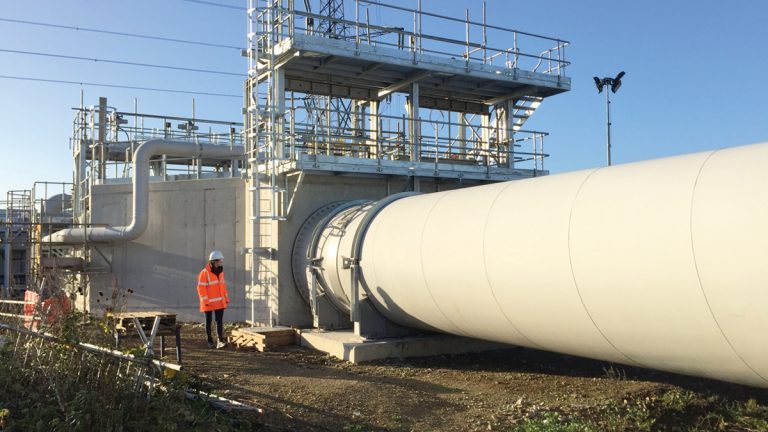
The collection chamber – courtesy of MVB JV
This construction sequence involved breaking-out the existing road down to the crown of the masonry arches in narrow strips perpendicular to the sewer barrels, before laying new mass concrete to bind the existing structure together. The new discharge chamber was then constructed on top of this mass concrete layer, leaving box-outs in the base of the new structure where the connections were to be formed.
Once the new reinforced concrete structure was completed the connections were cored through the crown of the masonry sewers and new overlaying mass concrete. Lengths of rebar extending from the crown to the invert had been pre-drilled and grouted into the masonry cores to support them, preventing them from dropping into the sewer below. Finally, drop pipes were put in place and the box-outs filled to complete construction.
Pipeline installation
The 2.4m diameter spiral welded steel transfer conduit pipes were supplied by Pipe Source UK Ltd in collaboration with George Green (Keighley) Ltd. They are typically 12m long with a 25mm wall thickness. Teekay couplings with vacuum rings were used at the pipe joints to accommodate for thermal expansion and contraction of the individual pipe sections.
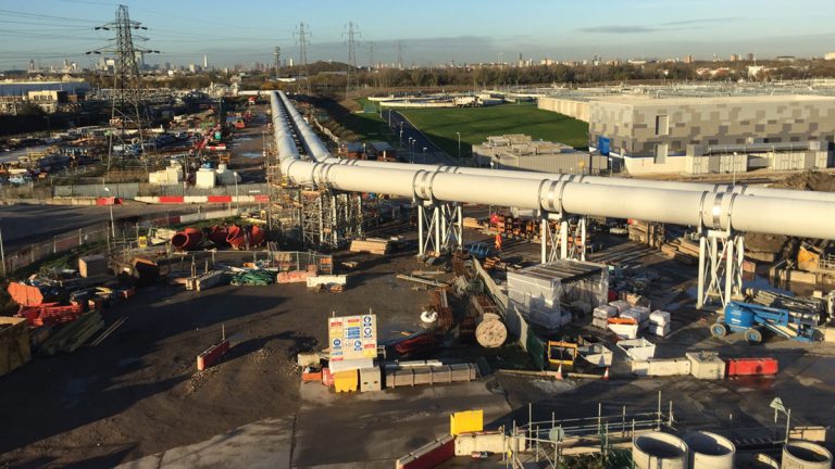
The Lee Tunnel Flow Transfer System – Courtesy of MVB JV
The transfer conduit pipeline route necessitates passing over the main site access road and under high voltage overhead powerlines. It was not possible to reroute the pipeline to avoid these crossings, so methods were developed to safely install and maintain the elevated pipes under the powerlines and at the long span road crossing.
The pipe sections beneath the powerlines were installed using an adapted shipping container forklift, enabling the pipes to be lifted 6m from ground level on to the steel towers, removing the need to use a crane in the vicinity of the powerlines. An access track was also provided to facilitate maintenance and inspections of the pipes and joints from ground level using telehandlers.
The original pipeline route had aimed to minimise the length of pipeline passing beneath the overhead powerlines by running alongside them and then crossing approximately perpendicularly. However, these construction and maintenance methods allowed the contractor to propose a more direct route passing obliquely under the powerlines, significantly reducing the overall length and avoiding passing through a potentially contaminated area that would have required significant earthworks.
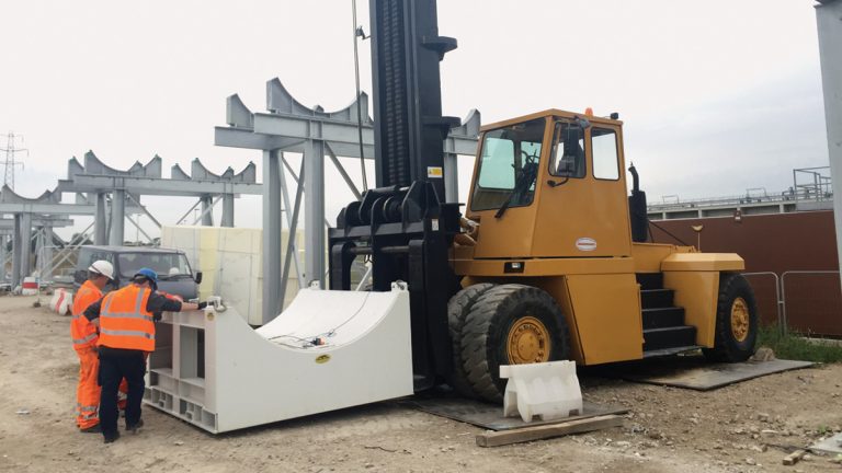
Forklift used to lift pipe sections up to 6m on to support towers – Courtesy of MVB JV
To avoid imposing any restrictions on vehicles accessing the site the pipeline was designed to cross over the main access road with a minimum clearance greater than the 5.7m design standard for structures vulnerable to vehicular impact.
The main access road also effectively formed a service corridor with numerous large gas mains, water pipes and cable ducts running in the verges either side of the road. To minimise operational impact the road crossing was increased to a clear span of 28m so that it would pass over all the services, avoiding the need to divert any existing services that would otherwise have clashed with piles for the support towers.
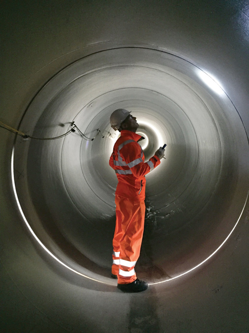
Internal inspection of the transfer conduit pipeline – Courtesy of MVB JV
Conclusion
By utilising available capacity on the Lee Tunnel shaft’s pumps the Flow Transfer System design was developed from a buried pipeline to an elevated gravity system. Through innovation to overcome design and construction challenges this resulted in greatly simplified construction, reduced impact on existing site operations, and eliminated the need for additional pumping.
The Flow Transfer System was commissioned as part of the Lee Tunnel on 28 January 2016 and will help to create a cleaner, healthier River Thames.


