
Blackpool South Surface Water Strategy (2018)
Aerial view of Fishers Field - Courtesy of MMB
The Blackpool South Surface Water Strategy is a £30m scheme aimed at improving bathing water quality along Blackpool’s golden mile. The project tackles the combined challenges of climate change, an aging Victorian sewer network, increasing urbanisation and a responsive catchment. The project’s objectives are the reduction in frequency and quality improvement of spills within the bathing water season. The contract was awarded by United Utilities (UU), the regional water company for the North West of England, to Mott MacDonald Bentley (MMB) in October 2016 and the project achieved Output in Use in April 2018. Planned contract completion was August 2018, with over 500,000 man hours worked on the scheme.
Background to scheme
The solution separates surface water from the existing combined sewer network across south Blackpool; a catchment equating to 700ha. The removal of surface water from existing sewers during heavy rainfall via a new sustainable urban drainage system, in combination with the construction of a new 4,000m3 capacity stormwater detention tank will reduce the number of network spills, reduce flooding and significantly enhance the quality of bathing waters.
The legislative driver for scheme was the Environment Agency’s National Environment Programme (NEP), which restricts the number of spills per bathing season. The contractual objectives for the scheme include:
- Reduced storm water spills at Lennox Gate and Manchester Square Pumping Stations to less than 57 over a 19 year period.
- Surface water separation with no detriment to water quality and flooding.
- 6mm 2D screening at the existing Lennox Gate PS.
The final solution will contribute to reviving the tourism sector within Blackpool. It will also provide large-scale operational carbon reductions as approximately 800,000m3 of surface water will no longer pass through Fleetwood WwTW prior to discharge to sea. The project required a detailed level of planning, organisation and liaison to minimise impacts on the local community and deliver the output ahead of regulatory deadlines.
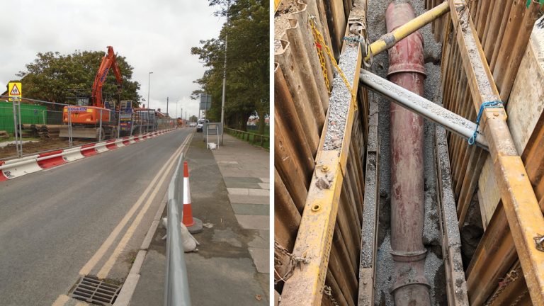
(left) Open cut pipelaying in Highfield Road and (right) rising main pipework dropping in level to avoid services – Courtesy of MMB
Scope of works
The overall scheme comprises:
- A network of new surface water sewers with a total length of 3km.
- A 4,000m3 underground stormwater detention tank.
- Two storm attenuation basins with a combined storage of 13,000m3.
- Provision of 6mm two-dimensional screening to storm flows at the existing Lennox Gate PS.
- A new 700l/s surface water pumping station at Magnolia Road.
- 2.6km of 700mm dia surface water rising main.
- Modifications to the existing Cornford Road Pumping Station.
- Associated power supply.
- Control and telemetry.
Network modelling
During the course of the project, significant scope reductions were achieved by optimisation of the network model. This was achieved by adopting a collaborative approach, with the MMB network modellers working very closely with their UU counterparts. The storm attenuation storage volume required was reduced from 24,730m3 to 15,390m3, the gravity sewer network reduced by 2.2km and 570m of rising main pipework was removed from the final design.
This reduction in scope resulted in significant CAPEX savings, reduced environmental impact and was beneficial in allowing the site team to deliver the scheme to meet the tight Output in Use date.
Ground conditions
The geology across the working area was complex and variable. The scheme largely comprised of buried structures within geologically recent strata comprising blown sands, peat, tidal deposits all variably overlying mixed glacial deposits. These challenging soils were combined with tidally influenced groundwater and multiple deeper pressurised aquifers. Managing and mitigating geotechnical risks was key to successfully and safely delivering the scheme.
Socotec carried out ground investigation across the full scheme as specified by MMB geotechnical design engineers. The investigation works allowed full understanding, definition and mitigation of ground conditions and risks through project design and construction.
Surface water separation
Previously in Blackpool South, surface water discharged to the sea via the river network. As the town of Blackpool developed, several watercourses were partially culverted and many were connected to the combined surface water and sewerage network.
To reduce pressure on this combined system, surface water flows have been disconnected from the system and discharged to the sea once more. Surface water that flows from the Marton Moss area of Blackpool has been intercepted and conveyed by a new open cut sewer in Midgeland Road and tunneled sewer from land south of Chapel Road, to Magnolia Pump Station.
Incoming flows are then pumped to a discharge chamber approximately 2.6km away via Midgeland Road, Highfield Road, Fishers Field, St. Anne’s Road and St Martin’s Road and then conveyed to the existing Harrowside culvert in St. Luke’s Road via a new gravity sewer in St. James’ Road.
During periods of high combined flows in the Harrowside culvert, the Magnolia Pump Station will be inhibited and surface water will be temporarily stored in two attenuation basins. This prevents an increase in surface flooding in the upstream catchment.
The key components of this new surface water system are:
- Midgeland Road Sewer: 1km x 750mm diameter surface water sewer to transfer separated surface water flow from various sources along Midgeland Road.
- MM1 Pipeline: 850m x 600mm diameter surface water sewer to transfer separated surface water flows from the industrial units near Ashworth Road.
- Magnolia PS: 8m diameter x 10m deep circular shaft with associated interceptor chamber, valve chamber, 300m long inlet tunnel, and control kiosk.
- MM2 & MM4 Basins: To meet the requirements of the proposed system at Magnolia Pump Station surface water storage is required upstream to cater for heavy storms. Two attenuation basins with a combined storage volume of 13,000m3 have been constructed.
- 2.6km x 700mm diameter ductile iron rising main: To convey the surface water flows from Magnolia Pump Station to discharge in to Harrowside culvert.
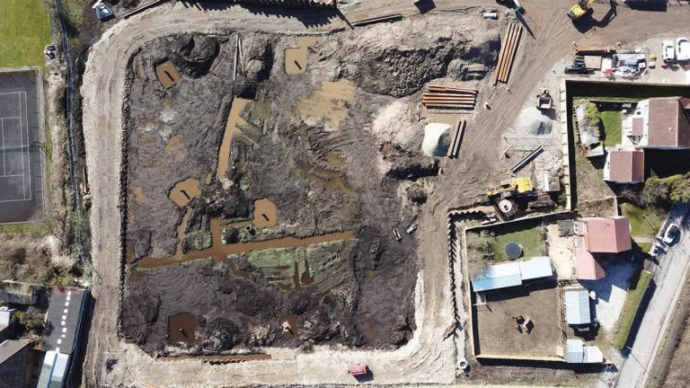
MM4 attenuation basin during construction – Courtesy of MMB
The works have been carried out by a combination of MMB direct labour, and subcontractors Waitings Construction, Cheetham Hill Construction and Ward and Burke. The site teams have experienced many challenges in the construction of this scheme, including:
- Geographic scale of the project.
- Restricted work areas.
- Third party liaison.
- Stakeholder agreements.
- Regulatory bodies.
- Poor ground conditions and high ground water.
- Congested utility services.
- Traffic management.
Combined installation techniques for the gravity and rising main pipelines include open-cut, hand-driven timber heading, and pipejacked micro-tunneling techniques. Construction of shallow open cut pipelines needed temporary control of running sands with interlocking sheet piles and internal dewatering wells. Over 1km of pipeline was constructed within tunnel to further mitigate ground risks, provide construction programme surety and minimise customer impact.
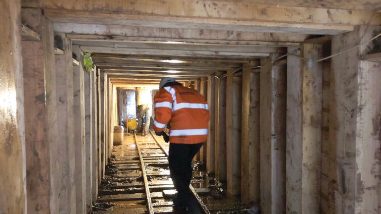
Completed timber heading structure – Courtesy of MMB
The basins were formed by combination of hard (perimeter sheet piled cut off walls) and soft (raised earth bunds) engineered solutions. Construction of attenuation basins required excavation through peat that, if dewatered, could result in long term settlement risks to local properties.
To mitigate this risk ground engineers adopted innovative new digital 3D geological modelling technologies to efficiently design and specify the perimeter cutoff walls. Construction of these hard-engineered solutions removed long term settlement risks to the adjacent properties.
Lennox Gate Pump Station
The Lennox Gate Pumping Station contains both dry weather and storm water pumps. The dry weather pumps transfer 1,400 l/s to Fleetwood WwTW and the storm pumps transfer 4,000 l/s to sea via the Harrowside Culvert. Prior to the project the storm flows were screened to 10mm via a drum screen.
Major modifications have been carried out to the existing pump station including removal of the existing screens and installation of 2 (No.) new Longwood Engineering escalator screens with a combined capacity of 4,000 l/s. The new 6mm 2D screens will treat storm water flows up to a 1 in 5 year return frequency. Modifications were also carried out to the screen launder and washwater systems. All these works were carried out in a live pumping station and required extensive temporary works and strategic planning to be carried out in association with UU’s operational staff.
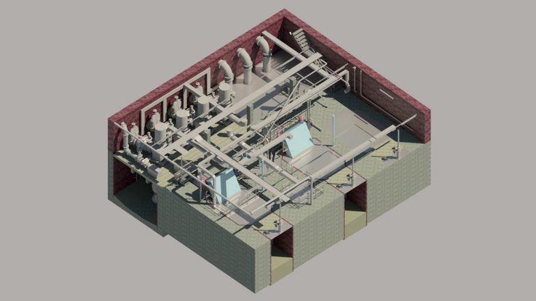
Lennox Gate Pump Station 3D model – Courtesy of MMB
A major challenge was the construction of a new dividing wall within the existing wet well, to provide separate dry weather and storm water pumping sumps. The construction of this 400mm thick RC wall within the sump of an operational pump station required major temporary works and carefully sequenced construction activities.
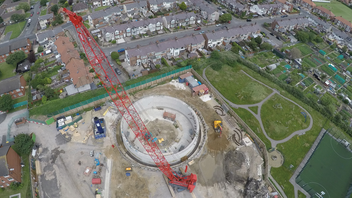
Fishers Field detention tank
At the nearby Fishers Field, a 25m diameter x 15m deep stormwater detention tank with a storage capacity of 4,000m3 has been constructed. The detention tank incorporated a VacFlushTM cleaning system supplied by CSO Group Ltd.
The tank is connected to the Lennox Gate Pumping Station via a new tunneled 1400mm diameter rising main. The connection onto the 70-year-old existing steel rising main was made by means of a prefabricated steel saddle.
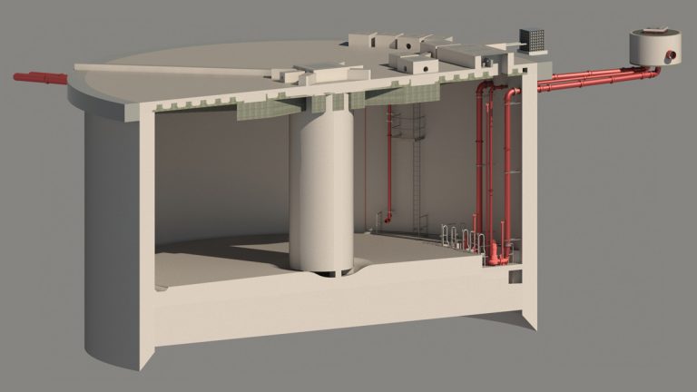
Fishers Field detention tank 3D model – Courtesy of MMB
Tunnelling and shafts
In order to accelerate the programme and to avoid the need to construct pipelines by open cut down narrow congested urban streets, MMB and UU decided to tunnel significant lengths of both gravity sewer and rising main.
Specialist shaft and tunneling contractor Ward & Burke Construction successfully delivered a significant proportion of the below ground elements of the scheme. Their key inputs have included design and construction of the 4,000m3 buried detention tank, over 1km of tunneled connecting pipework and nine additional below ground shafts forming new pumping stations, valve chambers and connections to the existing sewer network.
Further ground investigation by WJ Groundwater in Fishers Field was key to the design and safe construction of the detention tank. Preliminary investigations revealed a complex and variable geology and hydrogeological setting. Extensive investigation works, including large scale pumping tests, was valuable in informing hydrogeological understanding of the connectivity between three discreet aquifers and design of temporary groundwater control requirements.
The implementation of efficient ground water control during construction fully mitigated and removed the risk of inducing settlement within shallow peat and marine deposits, that could have resulted in settlement of hundreds of neighboring properties and associated buried infrastructure. Deep well dewatering confined within a temporary sheet piled cofferdam actively dewatered the uppermost aquifer and further de-pressurised deeper aquifers during shaft sinking.
The shaft design was optimised to take account of the identified ground risks, resulting in a larger diameter and shallower shaft. Construction required complex temporary works; installing an 18m deep sheet piled cofferdam using silent piling techniques. This method of piling was used to reduce vibration and noise levels for local residents and mitigate the risk of inducing settlement of shallow deposits from vibration.
The shaft was constructed as a cast in situ concrete caisson with a 1m wall thickness. The structure was constructed above ground before rapidly sinking in to position in a single operation over 4-weeks.
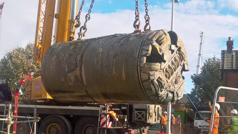
Tunnel boring machine being retrieved from the reception shaft – Courtesy of MMB
Over 1km of tunneled connecting pipework and new sewers has been successfully constructed. The 2m diameter pipejacked tunnels were constructed with a Herrenknecht TBM equipped with a closed face earth pressure balance shield to minimise potential surface settlements in poor ground.
Nine additional shafts for pumping stations, valve chambers and connections to existing sewers were constructed across the scheme. Shafts were up to 6m diameter and 11m deep, all formed as cast in situ concrete caissons. High groundwater in loose granular deposits required six shafts to be sunk under water balance as external dewatering was not possible due to risk of inducing settlement to local properties and infrastructure.
This work was successfully delivered within challenging, complex and highly variable ground conditions. All works were undertaken adjacent to existing residential properties without incident.
BIM and information management
MMB delivered the project to UU S13 Specification (Information Requirements), which adopts the principles of BS1192. A BIM Execution Plan (BEP) was returned to UU for evaluation to ensure the project addresses the requirements of S13. Part of the BEP included the Master Information Delivery Plan (MIDP); an agreed list of deliverables, which conform to the contract.
The MIDP includes scheduled dates for data to be submitted to UU for their acceptance or assurance via data drops aligned with UUs Technical Assurance Point (TAP) process. All asset centric data is prepared, complies and is delivered on UU’s BS1192 configured Common Data Environment (CDE) – Bentley ProjectWise.
The use of a CDE provides the following benefits for information management and collaborative working:
- Creates an inclusive project environment through efficient information sharing across teams.
- Improves the quality of information and decisions.
- Uses dynamic permissions to ensures that the right people have access to the right information at the right time.
- Avoids the risks associated with poor information management.
- Avoids typical inefficiencies of document exchange processes.
- Reduces information redundancy by acting as a ‘single source of truth’.
- Avoids loss of information.
To facilitate digital delivery, the following BIM technologies have been used at Blackpool:
- Laser scanning was carried out on an existing asset (Lennox Gate Pumping Station) reducing the health and safety risk by allowing the hazardous environment to be captured without the need to physically access it. The speed of capture reduced the amount of man hours required, as well as disruption and shut down time to the existing pumping station. Comprehensive data capture meant every detail was recorded, aiding the design process and eliminating the need for additional site visits with associated access and safety measures, which would have been required.
- Access, lifting and maintenance (ALM) reviews were delivered using virtual reality, allowing the whole project team and client to interact with information in a completely immersive native 3D experience; one which is spatially accurate, free to explore and interact with, unlocking new ways to engage, review and deliver a safer design.
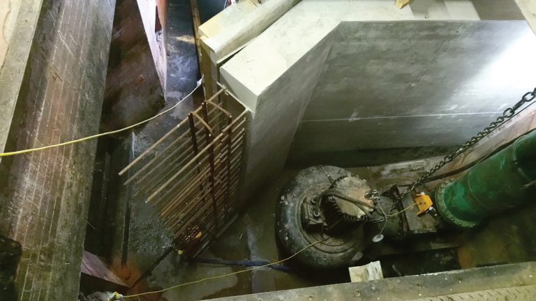
Reinforced concrete dividing wall under construction in Lennox Gate Pumping Station – Courtesy of MMB
Environmental benefits
The completed scheme will deliver the following benefits to the local and wider environment:
- Improved bathing water quality.
- Improved environmental quality of the ditch network as it is now disconnected from the combined sewerage system.
- Reduction in surface water flooding in the contributing catchment.
- Saving of approximately 200 tonnes per annum of operational carbon due to reduced flows at Fleetwood WwTW.
The local community was engaged early through local exhibitions and by preparation of a project exhibition centre. Continued engagement with stakeholders (Blackpool Council & Highways, Member of Parliament, local football clubs and Friends of the Beach) played a crucial role in the project success. A key success was being able to plan works efficiently around the annual Blackpool illuminations when traffic flow was critical to the local economic prosperity.
Construction activities across the project generated over 30,000m3 of spoil from excavations. All this material was successfully diverted from landfill and sustainably reused, partially on the project with remaining spoil being sustainably reused over other local developments.
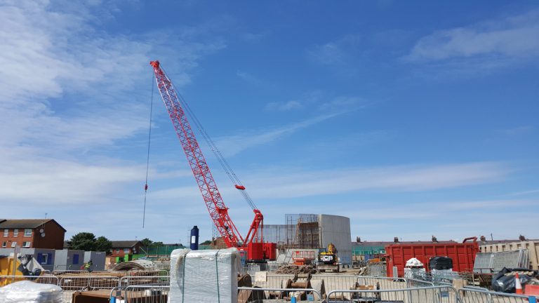
Fishers Field detention tank under construction – Courtesy of MMB
Summary
At the time of writing the project has achieved Output in Use and United Utilities has complied with their obligations under the Environment Agency’s National Environment Programme (NEP). Works are ongoing with Contract Completion due in August 2018.
The adoption of a collaborative approach to the network modelling has been invaluable in reducing project scope whilst still achieving the spill criteria. This has allowed the design and site teams to deliver a highly challenging project to a tight programme.