
Davyhulme WwTW Modernisation Project (2017)
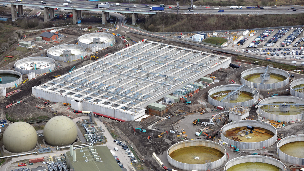
Davyhulme WwTW under construction - Courtesy of Laing O’Rourke
Davyhulme WwTW is United Utilities’ largest wastewater treatment works, which serves over one million people in Greater Manchester; it has been undergoing a £200 million modernisation process, which started on site in 2015 and is now close to construction completion. The upgrade is required to ensure it complies with tighter discharge consents and the impact of local population and trade growth. This year sees the start of the commissioning phase which will be completed by November 2017. The plant will be run by Laing O’Rourke commissioning staff and plant operators for six months to optimise the plant before handover, expected September 2018. The objective of this optimisation is to make Davyhulme the most efficient plant of this type in the UK, with stringent targets for power and chemical usage as well as significantly reduced operational working hours.
Background
The key primary and secondary treatment assets at Davyhulme date back to the 1960s and 1970s and have high energy and maintenance costs compared with modern activated sludge plants. The tightening of permit limits for discharge to the Manchester Ship Canal, the additional load from the advanced sludge digestion plant and Manchester’s predicted population growth present a risk that the existing assets may become even more inefficient in the future.
What is being provided?
The new works will screen future flows up to full treatment (FTFT) up to 8,264l/s through the new inlet works, comprising coarse and fine screens. The existing grit plant has been refurbished and adapted for larger grit skips. All channels and skip buildings are to be odour controlled to minimise offsite odour impact. A new inter-stage pumping station will convey 60% of FTFT to 6 (No.) new primary settlement tanks (PST). From there it will pass through a ten-lane nitrifying activated sludge plant (ASP) to 10 (No.) final settlement tanks (FST). The surplus activated sludge (SAS) will be removed and thickened in a new SAS treatment plant consisting of a 2,000m3 storage tank, 4 (No.) drum thickeners and a liquid polymer dosing plant.
Improved imported waste tanker facilities are also being provided with automatic sludge loggers.
The existing programmable logic controller (PLC) automation on the retained assets is to be migrated onto the distributed control system (DCS) giving better visibility and control of process units. New 15.5MVA dual power supplies have been installed by Electricity North West Ltd (ENWL) to give improved operational resilience to the whole site.
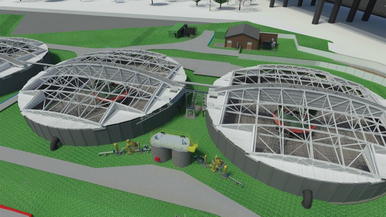
3D image of PSTs with covers removed – Courtesy of Laing O’Rourke
Undertakings
The scheme is the largest live wastewater treatment project currently being constructed in the UK. It is a collaborative design and build scheme between United Utilities and the principal contractor Laing O’Rourke.
Design for manufacture and assembly (DfMA)
To do more for less, United Utilities identified the use of offsite solutions and DfMA as a key efficiency strategy. DfMA was core to the Laing O’Rourke tender proposal and built on the expertise gained on previous treatment upgrades of major water industry sites, where the use of precast elements and off-site manufacture provided significant benefits for site safety, time and cost compared to traditional construction methods on site.
The team has built on this prior experience, furthering innovation where appropriate. This has required close liaison between the design disciplines to ensure each component provides the necessary structural and functional requirements.
By developing a detailed component tracker for coordinating production, delivery and offloading the team was able to overcome significant logistical constraints due to limited storage space available on site. Each component was delivered just-in-time to maximise installation efficiency and optimise hook time. Installation of cast-in items also virtually eliminated the requirements for drilling and fixing on precast elements.
Flow splitter chamber
This six-way flow splitter chamber was designed and fabricated by Pipex Ltd. Delivered to site in three sections, the finished dimensions were 6.3m square, 6.3m tall. This chamber arrived on site pre-assembled with pipework penetrations, weir plates and isolation hand stops. The coping level was also designed to receive the fixing for the odour control cover, which was also delivered to site in one piece with the hand railing brackets pre-installed.
Pre-installing steel reinforcement and permanent formwork in the factory environment reduced construction time, minimising the requirement for working at height and within deep excavations. This significantly reduced construction risk and improved the build quality of the finished product.
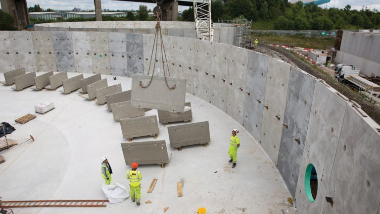
Bison Abetong precast panels and launders – Courtesy of Laing O’Rourke
PST and FST tanks
The 6 (No.) polygonal PSTs and 10 (No.) FSTs were constructed using Bison Abetong C14 pre-stressed wall panels and outfall launder channels founded on a piled cast in situ base slab. The vertical joints between the precast panels and the horizontal joint between the bottom slab and the panels are grouted with concrete. The circumferential mono strands are then post-tensioned and once this is complete all the strand ducts are pumped full with grout.
Each of the 41m diameter x 5m tall PSTs consists of 54 (No.) precast wall panels with a unit weight of 6.3 tonnes with the 46m diameter FSTs comprising 61 (No.) panels. Early engagement between the manufacturer, Bison, and the design team identified the opportunity to slightly reduce the height of the PST Abetong panels, which in turn allowed the supplier to use one mould to cast two panels at the same time, increasing production throughput during manufacture.
When compared to traditional construction methods, Laing O’Rourke’s use of Abetong precast panels has resulted in 2,466 fewer construction working days across all 16 (No.) tanks.
Activated sludge plant
The ASP is made up of a 7,111m3 common anoxic zone and 10 (No.) aeration lanes; each lane is 10.5m wide and 9.5m deep. At 158m in length, these are as long as the Blackpool tower is tall, with one lane taking over 3 million pints to fill. The civil design utilised over 2,000 (No.) precast concrete units, consisting of the Explore precast twin wall system and Bison precast beams and walkways, each 3D modelled in detail to enable extensive clash detection on both the precast units and the in situ stitch reinforcement. This additional effort at the design stage resulted in no clashes being recorded during construction.
Laing O’Rourke drew on experience from working on constrained central London construction sites to overcome issues with limited available storage space both on site and at the factories. Working closely with the supply chain and Explore Transport, the team challenged the construction sequence and manufacturing programme, optimising just-in-time manufacture and delivery and utilising of offsite staging areas to buffer deliveries to site. This ultimately improved productivity on site and minimised damage to precast units through storage and loading.
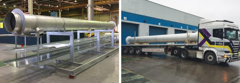
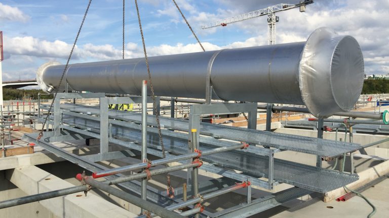
(left) ASP pipebridge in factory and (right) ASP pipebridge delivery – Courtesy of Crown House Technologies Manufacturing
During the tender construction review the width of the lanes was increased to allow Select tower cranes to be installed on rails within the lanes. This reduced the number and types of cranes on site, which in turn reduced the requirements for additional crane pads, haulage roads and lay down areas. By utilising split shifts to place in situ concrete during the day and precast units in the evening, the hook time of these cranes was optimised to maximise productivity.
Laing O’Rourke’s commitment to BIM and digital engineering meant that the project benefitted from pre-building the ASP in a virtual collaborative data environment. This led to changes in build tolerances and joint design, but more importantly let the construction team visualise installation sequences and constraints well in advance of construction works. This allowed temporary work to be designed and optimised earlier; generating significant safety and programme benefits.
For the ASP, Crown House Technologies provided the required galvanised structural steelwork: 57 (No.) walkway bridges, 28 (No.) mixer platforms and 15 (No.) step-overs. These came pre-installed with stainless steel pipework, handrailing and cable trays.
The collaborative approach to the construction of the ASP from tender stage to construction has saved 6,800 working days and generated significant savings.
ASP pipebridge installation – Courtesy of Crown House Technologies Manufacturing
Motor control centres (MCC)
As part of the project, 14 (No.) new MCCs enclosed in GRP kiosks were required around the site. Installation of 2 (No.) MCCs was critical to releasing subsequent construction activities. With assistance from the supply chain, Laing O’Rourke created an innovative design where the MCC was pre-assembled off site on a steel frame, inside a GRP kiosk complete with building services. Quality checks and factory acceptance tests were carried out off site prior to transportation.
Smaller MCC kiosks consisted of a single pod design with two of the larger U-shaped MCCs being housed within a double pod design. The largest of these was 14m long and 7.5m wide for the split-kiosk design. Excluding crane set up, each MCC pod was installed on the cast in situ base within 15 minutes. The traditional method to install kiosks of this size would have been to install the flat-packed kiosk panels over a two-week period with building services, heating, lighting, support steelwork, flooring and internal cabling following afterwards.
Separately, the MCC would be built up at the supplier’s factory, tested and then broken down into 1.5m to 3m-wide tiers for delivery. These would need to be reconnected at site and re-tested.
For the largest of the MCCs , this would have required over 7,000 (No.) reconnections and would have taken four people two weeks to complete. This was reduced to just 16 (No.) reconnections on site using the DfMA solution. By building the MCCs within the kiosks, supplier Lloyd Morris Electrical Ltd (LME), realised an unexpected benefit. By not using the factory to assemble the MCCs they freed up production space that would have normally been used, therefore allowing them to increase throughput.
This approach to DfMA has so far saved 140 working days and, generated significant interest from other projects.
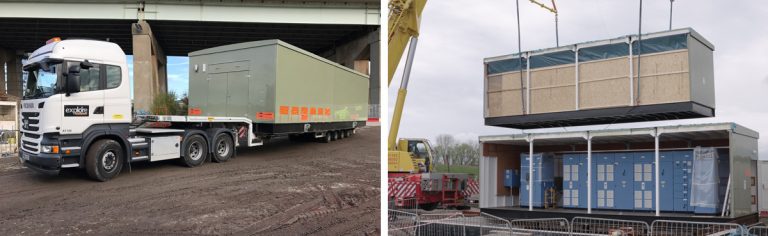
(left) Low loader MCC delivery and (right) MCC lifted into place – Courtesy of Laing O’Rourke
Building information modelling (BIM)
The BIM, or digital engineering execution plan has proved to be invaluable in setting the rules on the exchange of 3D models, data, their required naming conventions, location, units and level of detail required. This project-centric information is to be created, controlled and stored on United Utilities’ Common Data Environment (CDE), which is compliant to BS 1192.
Laing O’Rourke’s digital engineering (DE) team has created an overall site federated model that consists of 142 (No.) civil, 271 (No.) mechanical, 26 (No.) electrical and 304 (No.) supplier models covering the new works across the 200-acre site. Working collaboratively with the civil design JV partners and supply chain, the DE team has created workflows from the various different software packages to ensure efficient transfer of design information.
The model has not only been used for the expected BIM requirements of clash detection and design reviews, but also for 4D construction sequencing, cut and fill volume calculations, temporary works design, induction videos, visual risk assessments and method statements, procurement and design management progress, access and lifting reviews, hazard and operability studies and tracking DfMA components. Laing O’Rourke also called upon their experience in the use of Fieldview on other major construction projects. By adapting it to digitally capture the installation, testing and commissioning data, the team saved time in the back office when reporting on progress. This data will be passed onto United Utilities for use in their asset data management system.
One of the aims of the DfMA component tracking was to provide a live link to the progress of precast components being produced at Laing O’Rourke’s manufacturing facility. The SAP database was linked to the 3D model to visualise the status of each component, highlighting potential delays and ensuring call-offs could be managed based upon a live schedule. This allowed the site engineers to quickly and easily view the status of all components in real time and increase accuracy in correct call-offs.
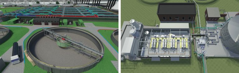
(left) 3D image of FSTs, MCCs, blower house and the ASP lanes and (right) 3D image of SAS treatment plant – Courtesy of Laing O’Rourke
Surplus activated sludge treatment plant (SAS)
This collaborative approach of digital design integration and visualisation has helped Laing O’Rourke complete construction of the SAS plant three months ahead of programme. The creation of the 3D model allowed Laing O’Rourke to review and confirm early in the design process that the new plant could be installed inside an existing building, whilst still meeting the client’s access, lifting and maintenance requirements. The new plant will improve the quality of the sludge treatment and in turn reduce the loading on the existing assets.
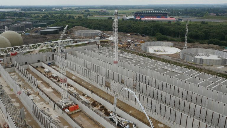
Davyhulme under construction – Courtesy of Laing O’Rourke
Conclusion
Laing O’Rourke’s considered approach to DfMA and digital engineering from the tender designs to the final construction, in collaboration with United Utilities, has saved money and time with a saving of over 11,000 working days on site. This significantly contributed to the exemplary health and safety performance of the project, currently over 1.3 million working hours on site without a reportable incident.
It will also leave United Utilities with a greatly improved major asset, fit for the envisaged future demands of Greater Manchester.
Editor’s Note
This article follows on from the Davyhulme WwTW 2016: Design & Construction Phase published in UK Water Projects. A subsequent article was published in 2019 documenting the final stage of the Davyhulme WwTW Modernisation Project.