GoFlo
Sandown Surface Water Abstraction
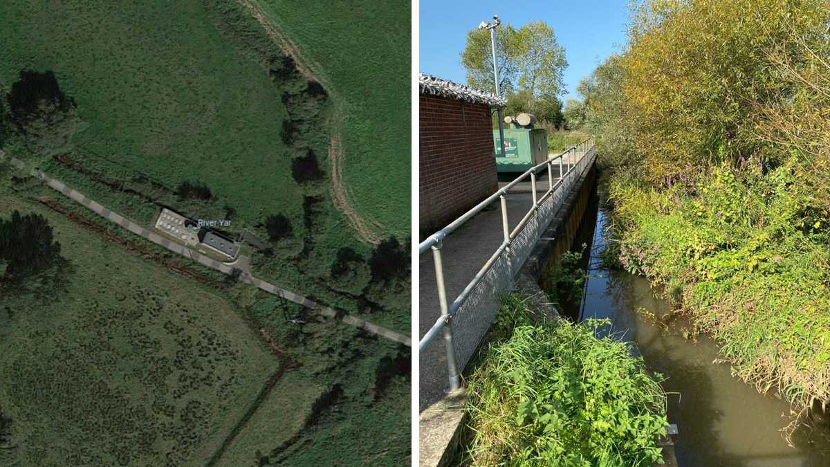
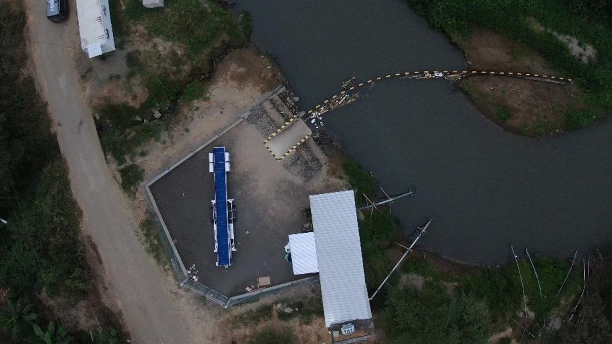
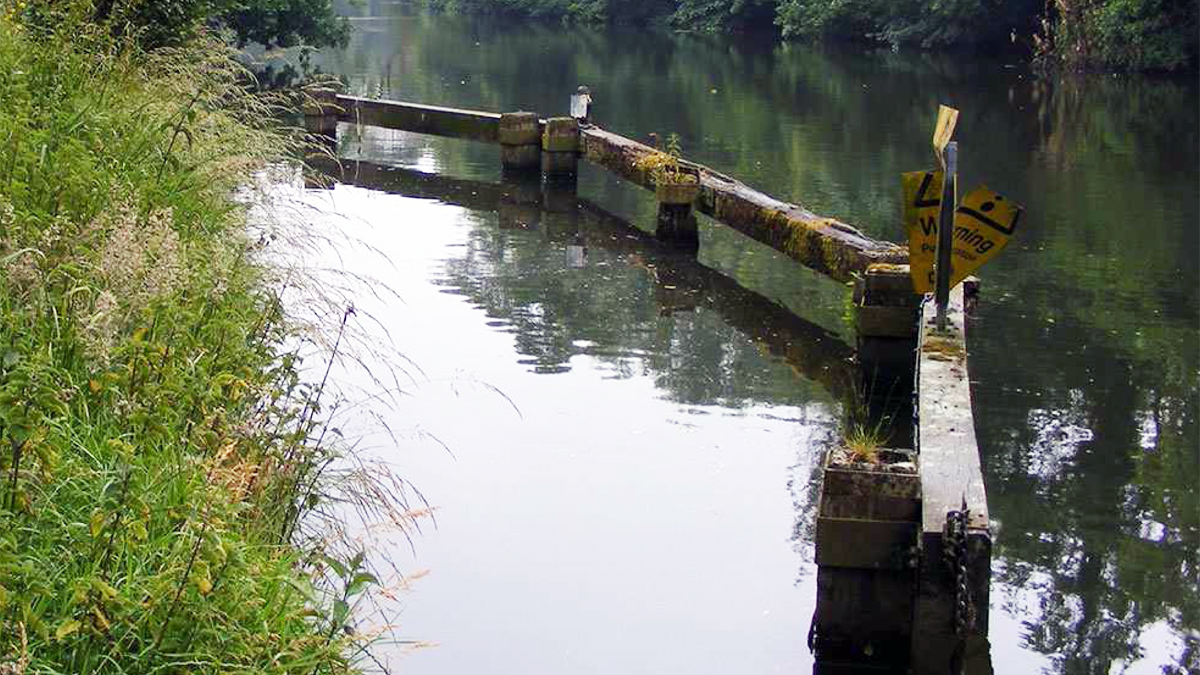
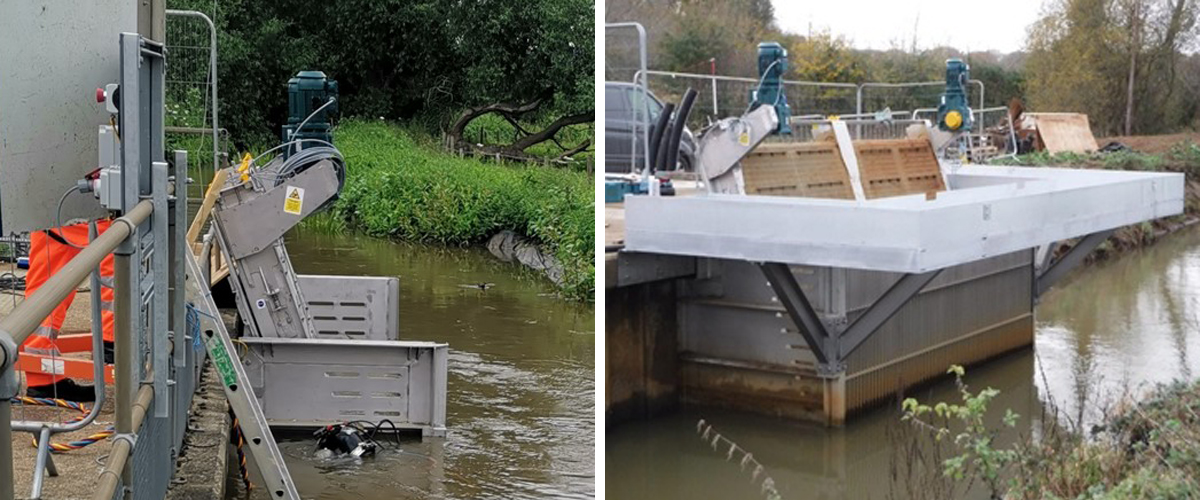
(left) Aerial view of Sandown intake and pump house and (right) Sandown Pumping Station, looking upstream
Sandown Surface Water Abstraction (SWA) is a pumping station abstraction from the River Yar on the Isle of White, which feeds raw water into the Sandown WTW. The pumping station is several hundred metres from the water treatment works, and sits alongside the popular and busy Red Squirrel Trail walking route and cycle path. Along with many other water intakes throughout the UK, Southern Water had to upgrade the water intake screens to be compliant with the Eel Regulations, which meant a bar-spacing that did not exceed 2mm and an approach velocity that did not exceed 0.25 m/s. The existing intake structure was built in the early 1980s and consisted of interlocking steel sheet pile walls, capped with a concrete slab. Manholes on top of the slab provided access to the sump pumps, valves and pipe/cable ducts. The river bed in front of the structure is a flat concrete slab, which could provide a good base for the eel screens to sit on if needed.
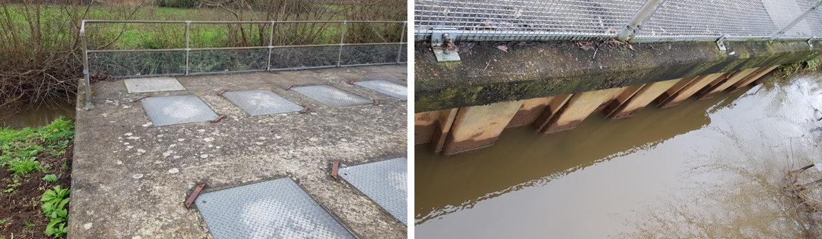
(left) Concrete slab on top of the sheet-pile pump and valve enclosure and (right) sheet-pile walls that make up the pump enclosure
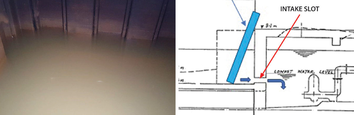
(left) View inside the pump chamber, looking at the sheet piling adjacent to the river. Below the waterline is the 0.2m high x 3m wide slot where the river water is drawn through. (right) close-up of intake drawing showing ‘letterbox’ slot
The existing intake did not have any screening; hence fish, eels and other objects could potentially enter the pump chamber.
CMDP was the main contractor for the project, and GoFlo worked closely with them from the early design stages to the final commissioning to ensure an optimal solution was developed.
With a maximum abstraction flow rate of 0.278 m3/ second, the approach velocity through the existing intake slot in the sheet pile wall would exceed the maximum specified in the Eel Regulations. This meant that would it would not be possible to install the GoFlo screens inside the existing pump building and would have to be installed externally to the existing building.
An added complication was that the intake could not be shut down for more than 8 hours without severely disrupting the water supply to the Isle of White, which would not be acceptable, so the solution had to be designed to be installed into a working intake using divers.
GoFlo had a similar issue at another Southern Water site (Springfield), and for that site designed a fabricated ‘intake box’ system that could be installed by divers. This system worked well, so the principle was used for Sandown, even though the water depth at Springfield was 4.5m, whereas at Sandown it is typically only 600mm.
The width of the screens at 3.55m has been determined by the minimum depth of water in the river (0.438m) while still having to meet the 0.25 m/s approach velocity under the Eel Regulations while abstracting the maximum flow rate.
Site survey
The design process started with a detailed survey of the intake area. As is the case with many sheet-pile structures, nothing was exactly plumb or square, so because the fabricated intake box we would have to manufacture had to fit perfectly, first time, we had to enter the river and make plywood templates that fitted the profile of the existing structure perfectly. At the same time a detailed level-survey was conducted on the river bed concrete slab. We took the wooden templates away and turned them into precise profile data points that could be used to build an accurate 3D model of the existing structure in our CAD system. Based on that, we could design the intake box to fit perfectly.
Design
Due to how the in-pans and out-pans of the sheet piling were positioned, the bolted connections onto the Intake Box at the upstream end was on an out-pan and at the downstream end on an in-pan, so the left and right-hand intake box sides being different widths (1560mm and 1450mm).
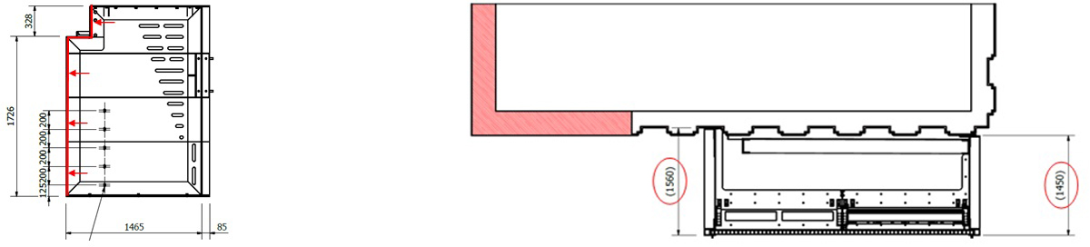
(left) Intake box side drawing and (right) plan drawing showing new intake box attached to existing sheet-pile structure
The intake box is a stainless steel fabricated box made up of the two sides and a baseplate that were assembled into a finished box on-site. The structure is designed to be a rigid structure so it could support the screens in the inclined ‘operating’ and vertical ‘service’ positions. The Intake Box structure also had the walkways fixed to it, which in turn have the security fencing fixed to them, so had to be designed to be very strong.
A course bar screen with 50 mm bar-spacing was incorporated into the intake box, just upstream of the screens. This bar screen will protect the fine GoFlo screen meshes from large debris which could deform or puncture the screen face during flood flow conditions, but also keep any swimmers away from the moving parts!
An advantage of having the screens perpendicular to the river flow will reduce the possibility of the bar screen collecting debris; the river passing flow tending to pull material away from the bars.
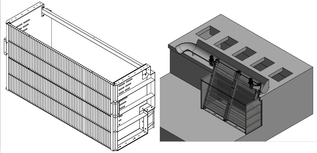
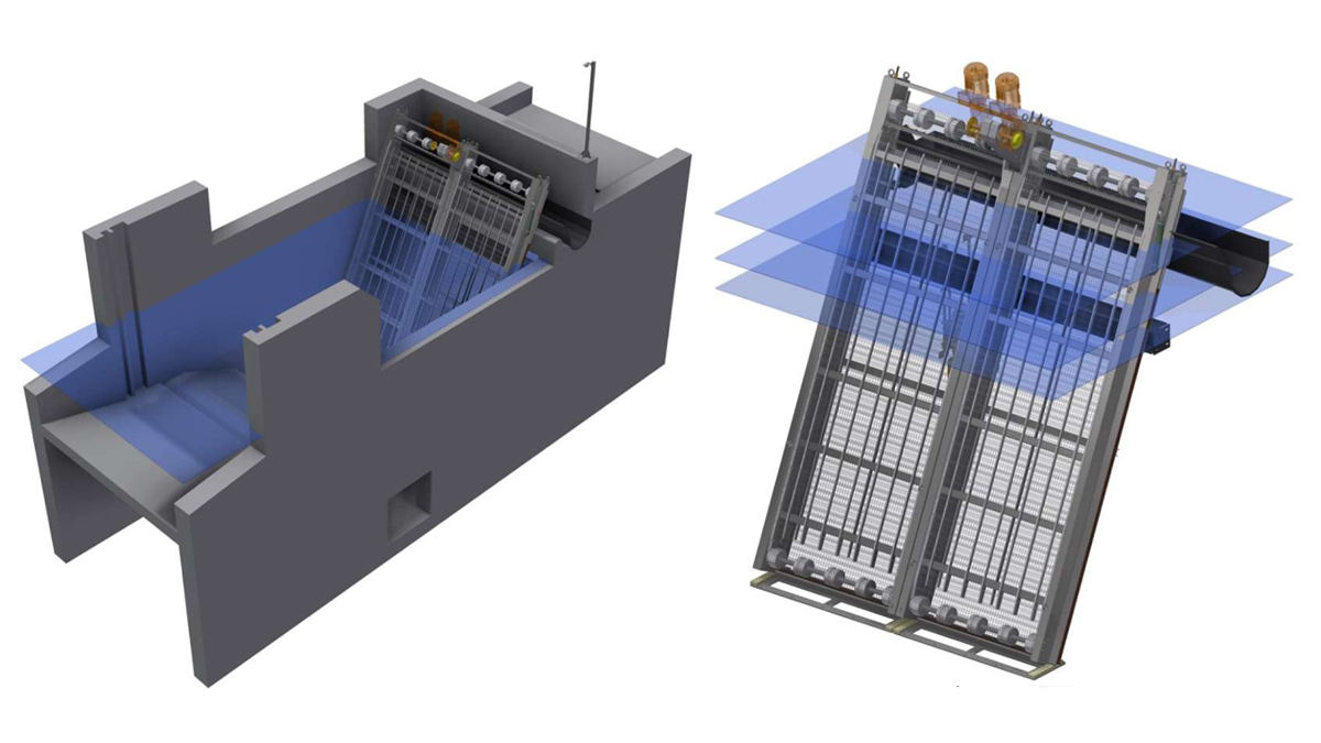
(left) Drawing of intake box with course bar screen attached to upstream face and (right) drawing showing GoFlo screens, debris trough and intake box attached to existing structure
The debris captured by the screens is returned to the river via the debris trough and return channel, but about 5m downstream, so the likelihood of material being pulled back into the screens is minimised.
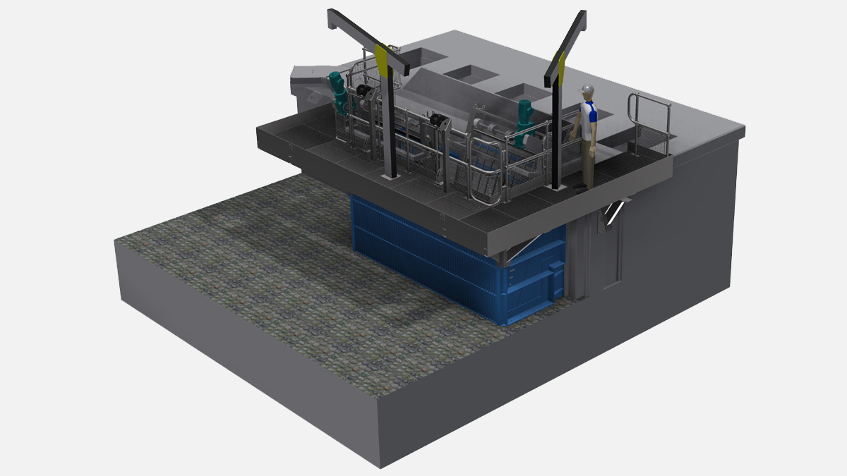
The walkway structure incorporates davit sockets and removable winches. The winches are used for pulling the screens from their inclined ‘operating’ position to the vertical ‘service’ position. From here, the screen’s motor/gearbox and drive system can be accessed safely. Should a motor need to be taken off the screen, a portable davit can be mounted in a dedicated floor socket and the motor lifted up and over the handrail onto a trolley for transport away from the area.
Complete 3D model of proposed GoFlo system attached to the historic structure
Installation
This started with the river bank and floor being cleared of any silt and stones etc. Next, the intake box was assembled, including adding some temporary diagonal braces to keep the sides an
baseplate square and to prevent the structure flexing during lifting. Once the intake box was in the river and fixed in position the diagonal braces were removed.
The intake box was fixed down to the concrete apron using stainless steel M16 resin-fixed anchors, and to the vertical sheet pile wall by drilling a tapping M12 bolted fixings. Installing such a structure in a flowing river was a hazardous operation, especially with divers in the water to guide it into position, drill and install the fixings into the wall and river bed. Underwater visibility was very poor due to unseasonal heavy rainfall and increased river flow. The divers had to be in constant radio contact with the dive support team on the bank. The divers also had a live video feed to the team in the control room so they could be guided to the fixing locations.
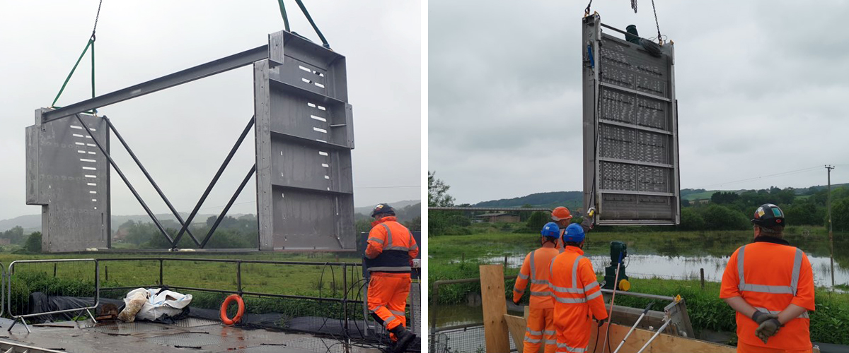
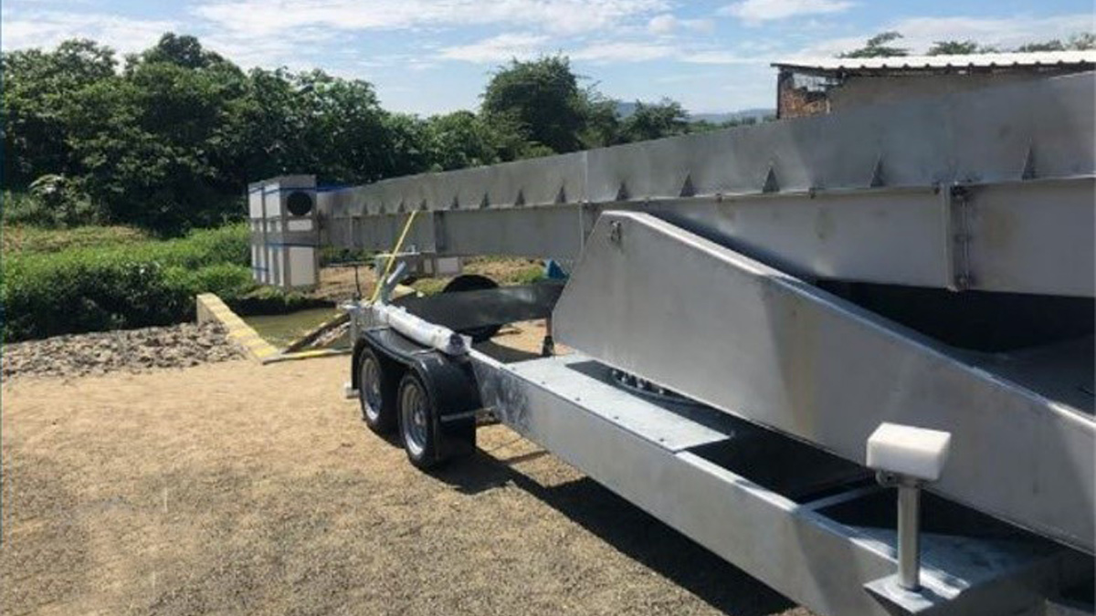
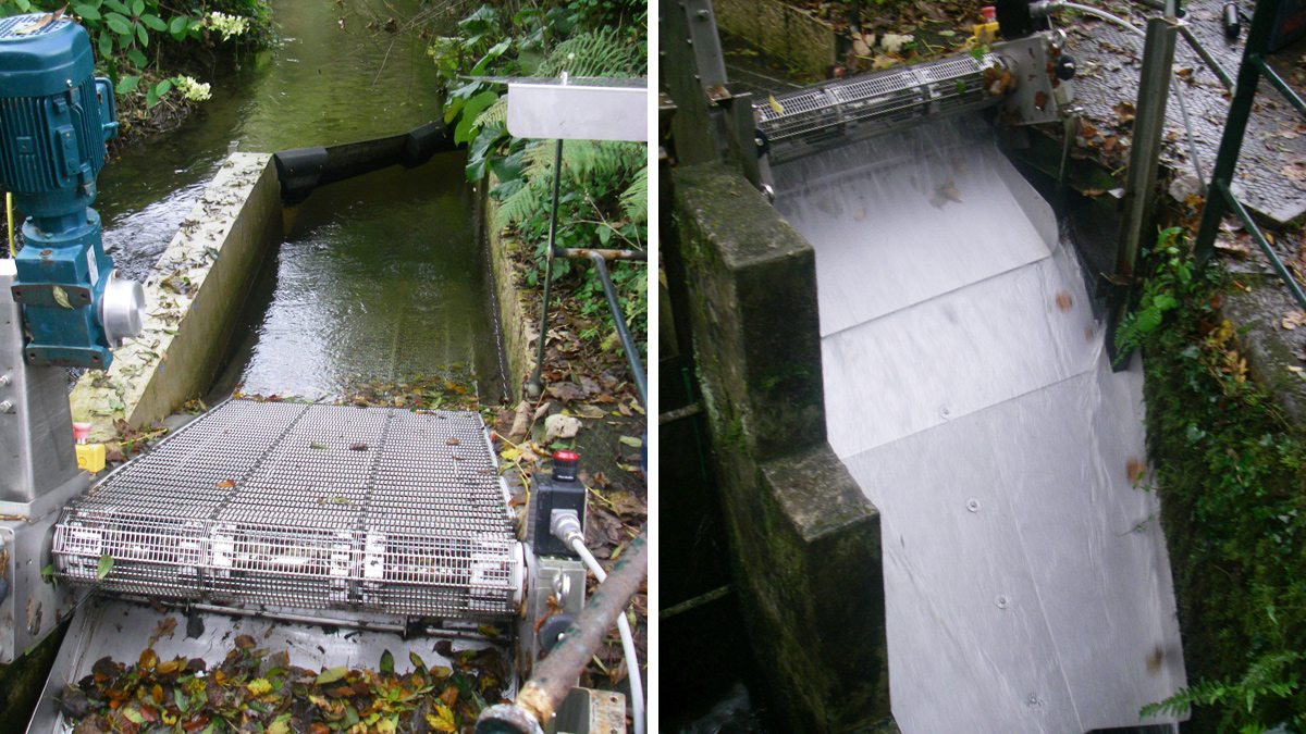
(left) Lifting the intake box into the river and (right) lifting the first of the GoFlo screens into the intake box
Once the intake box was fixed in place the two GoFlo screens were lifted into position. This is a relatively quick operation due to the integrated ‘pivoting frame’, which are guide rails allowing the screen to be lifted in vertically and accurately guide the screen into position, even when the intake is flooded with zero visibility.
At this point the screens were connected to a temporary control panel and a wooden debris trough was constructed to allow the screens to be put into operation. The screens had to be put into service immediately because of the looming deadline to make the Intake Eel Regulations compliant.
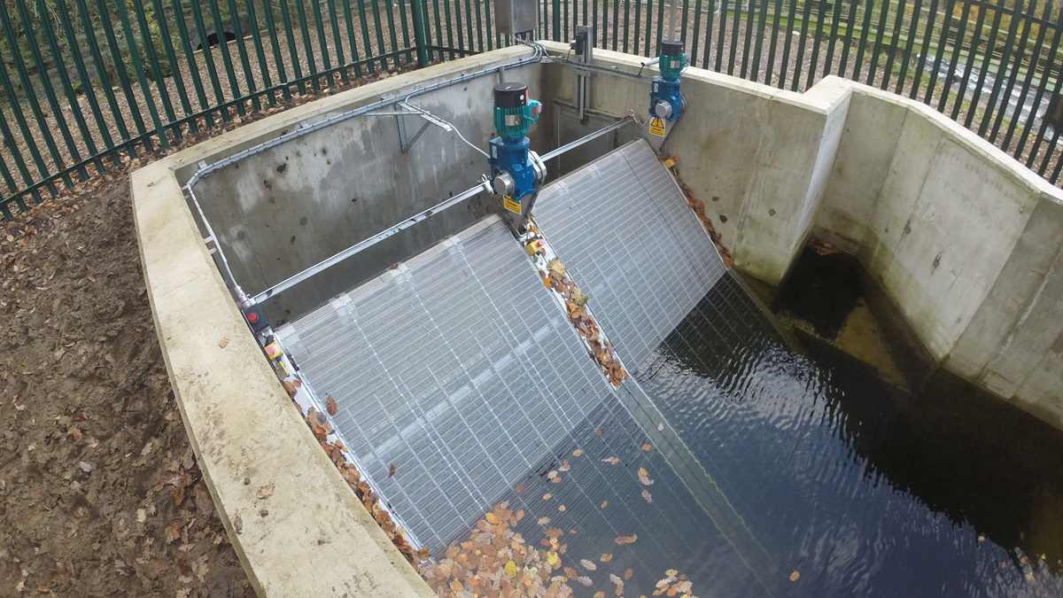
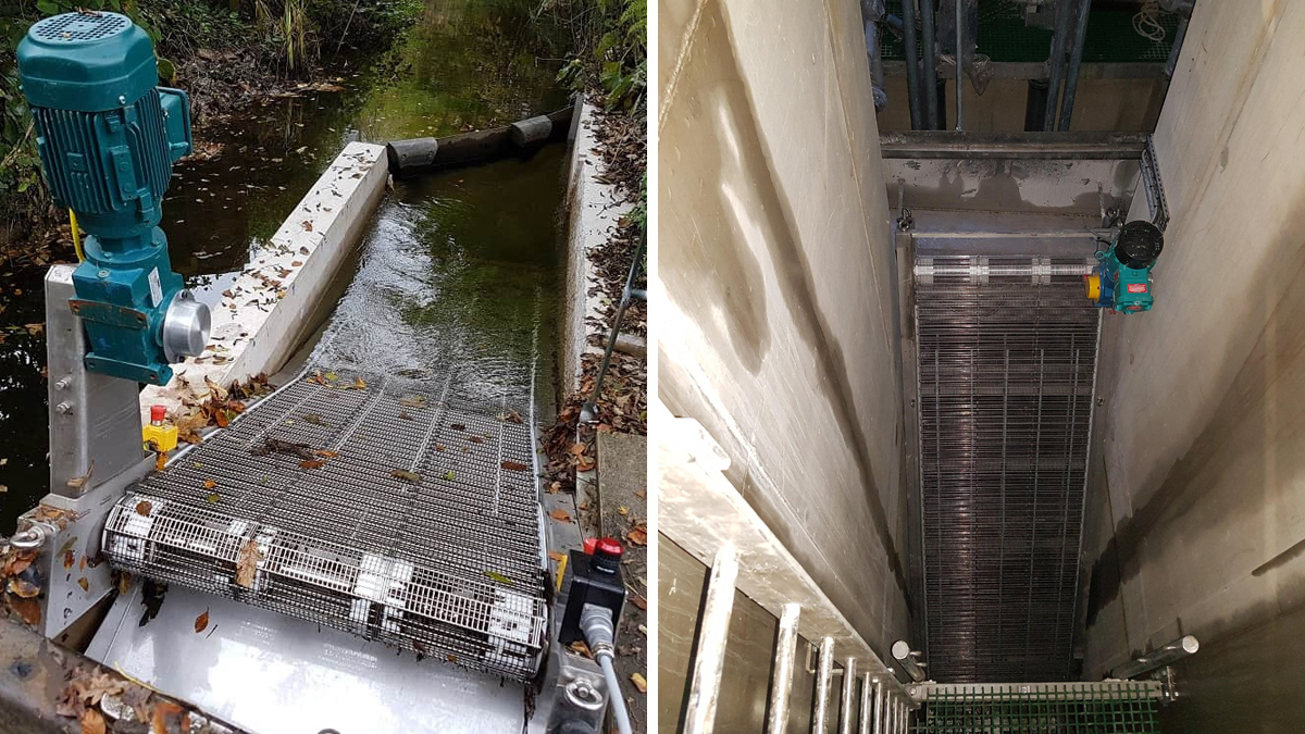
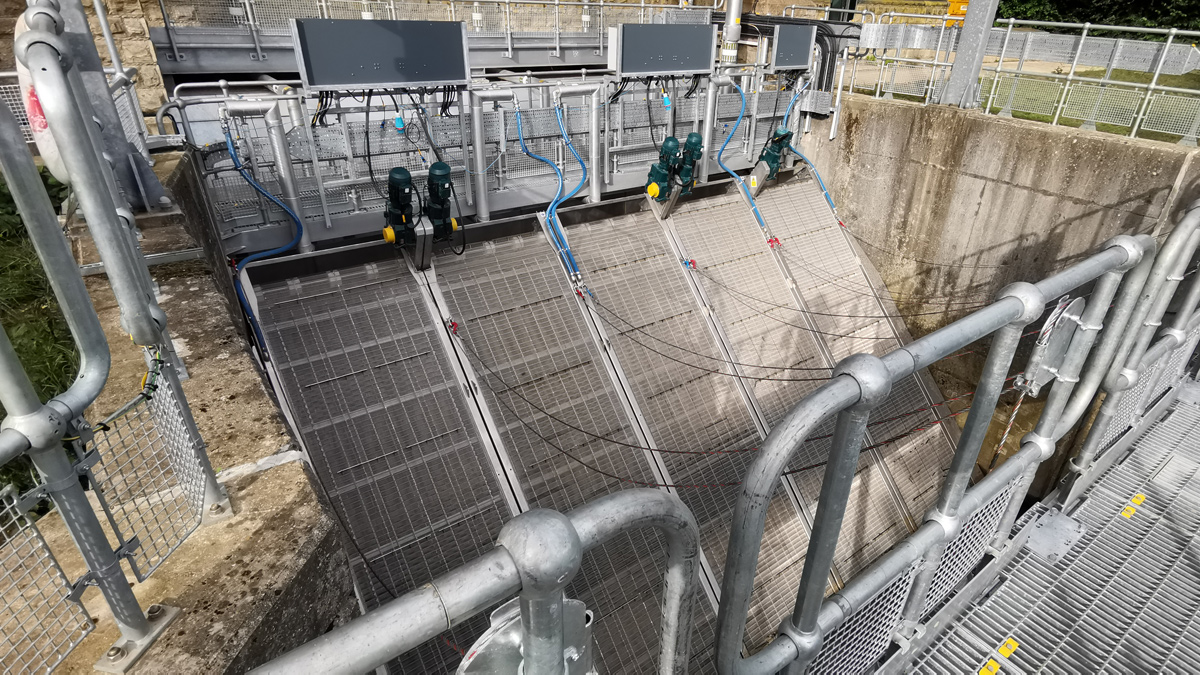
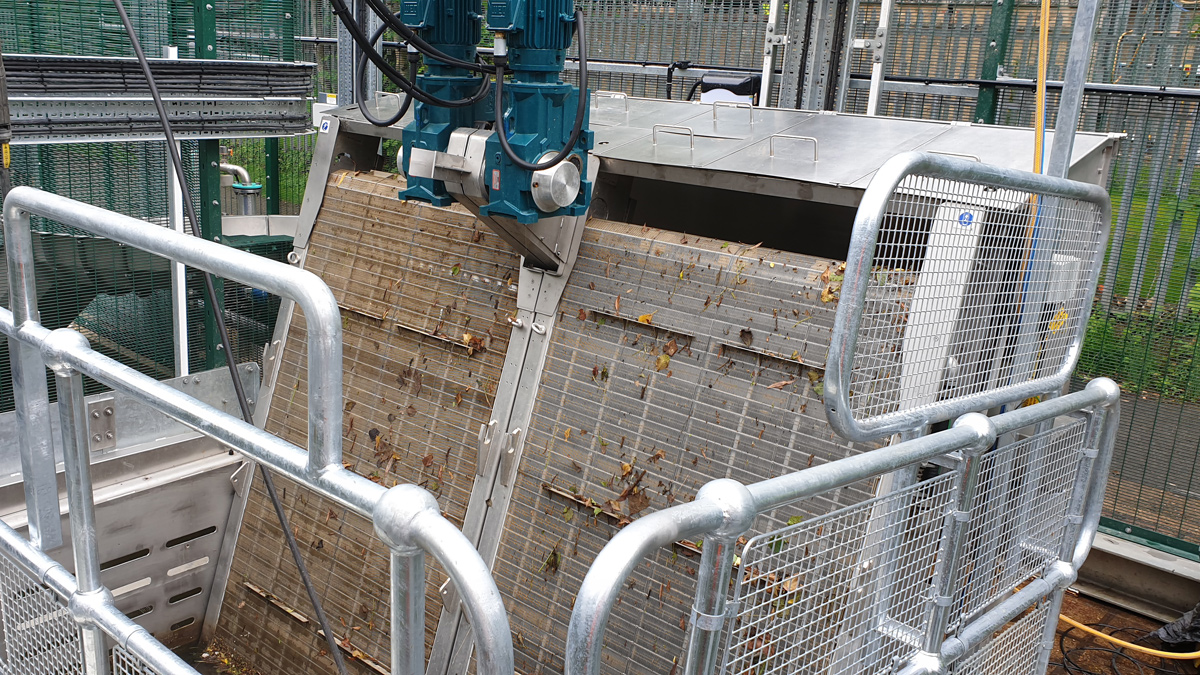
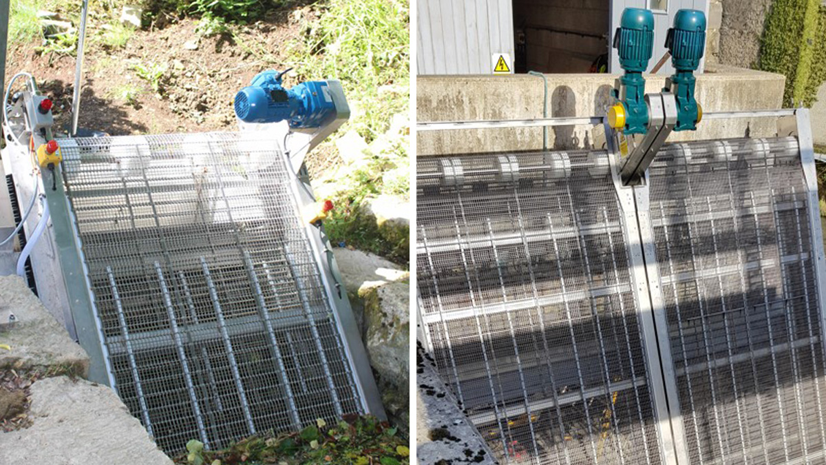
(left) The first screen in position on the intake box and (right) both GoFlo screens in position in the intake box
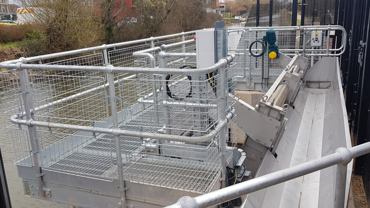
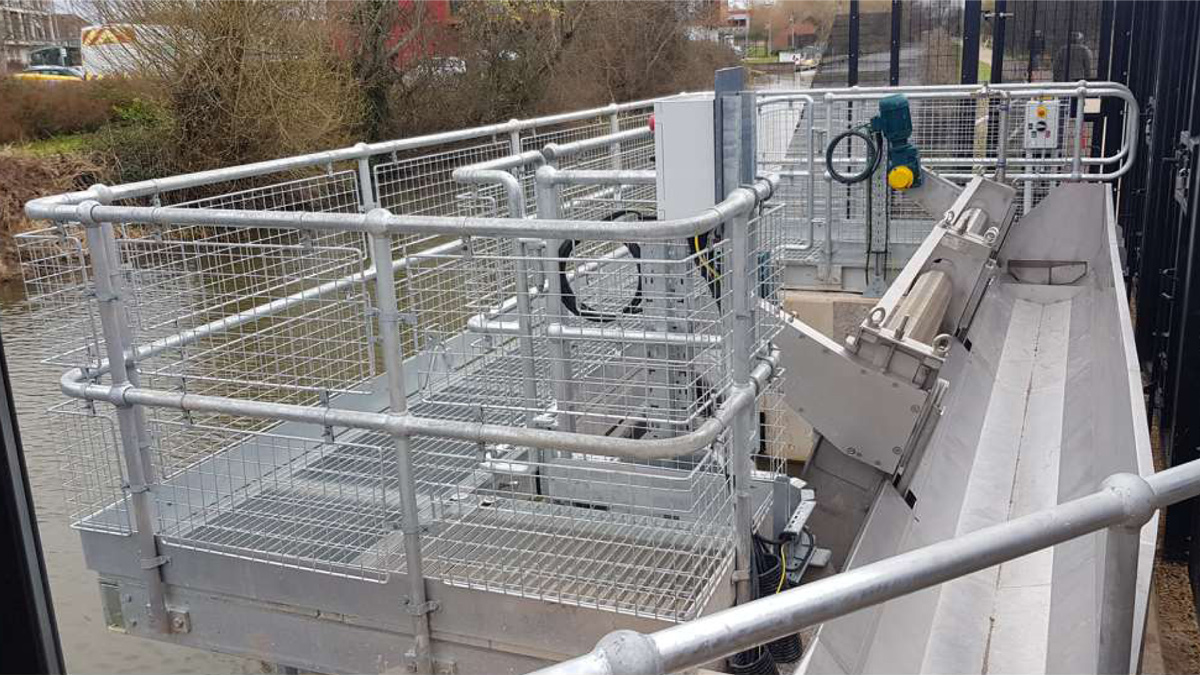
A few months later the walkways, debris trough and security fencing were fitted, which all bolted directly to the intake box. The assembly was all designed in detail using 3D CAD software by GoFlo, then the constituent parts laser-profiled and CNC folded, finally being welded together. The walkways were installed in two days, and the debris trough in a similar time, which is testament to the accuracy of the design and fabrication undertaken by GoFlo.
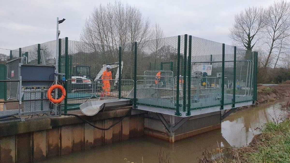
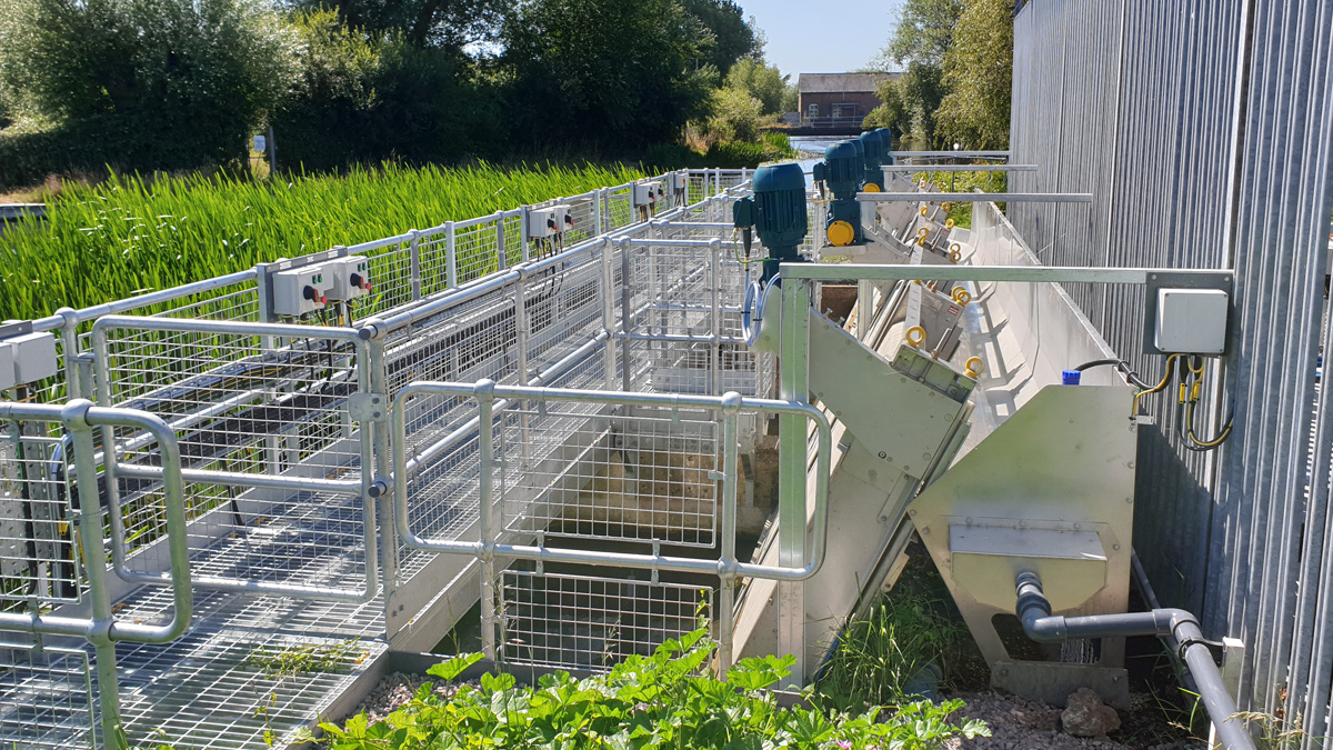
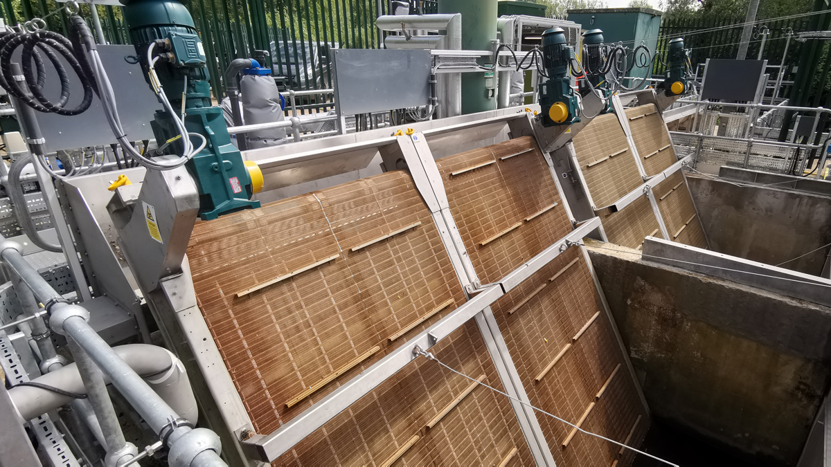
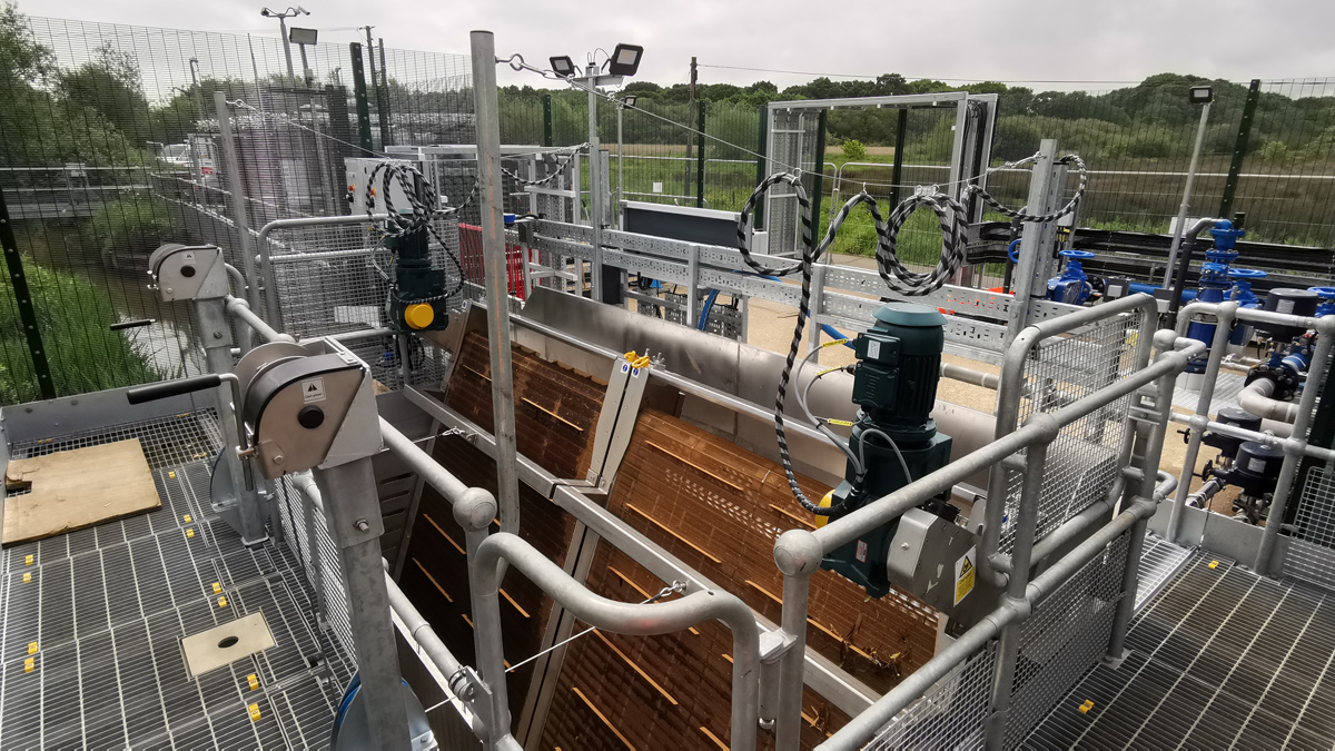
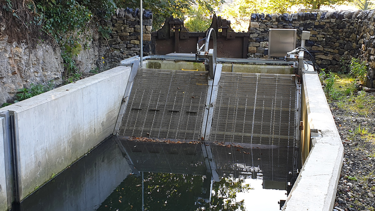
Completed GoFlo screen installation
For more information: GoFlo Screens Ltd | +44 (0)1453 884400 | www.gofloscreens.co.uk
![]()
For More Information, contact us at http://www.gofloscreens.co.uk