GoFlo
Springfield Surface Water Abstraction
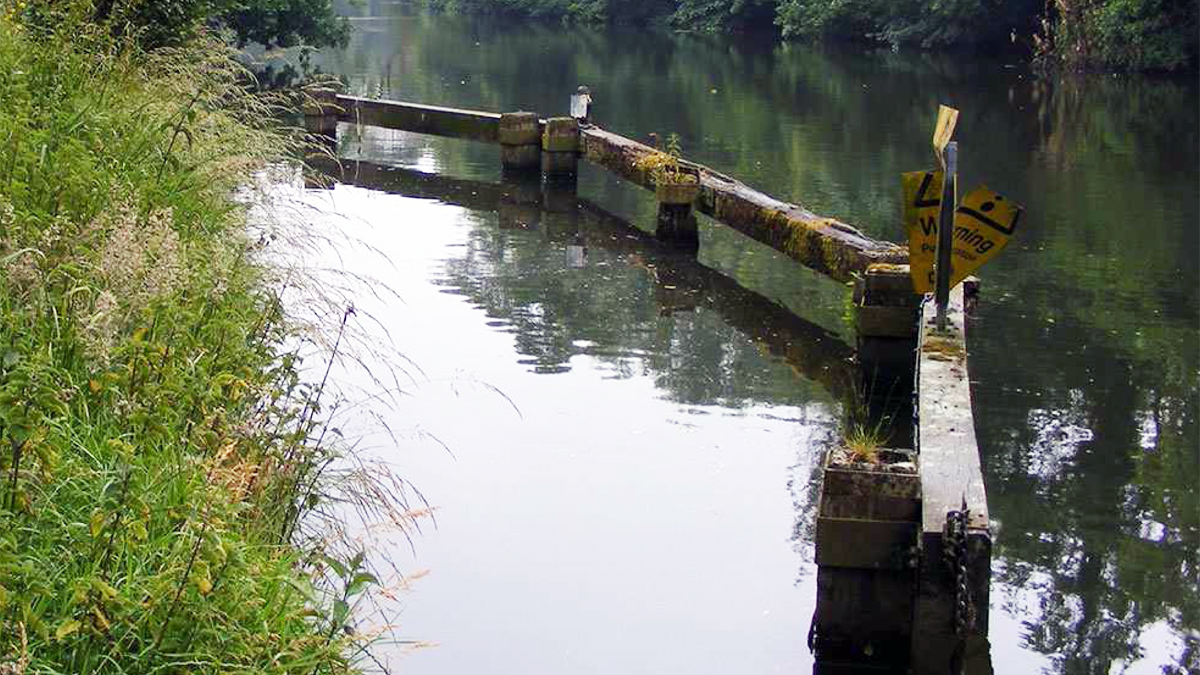
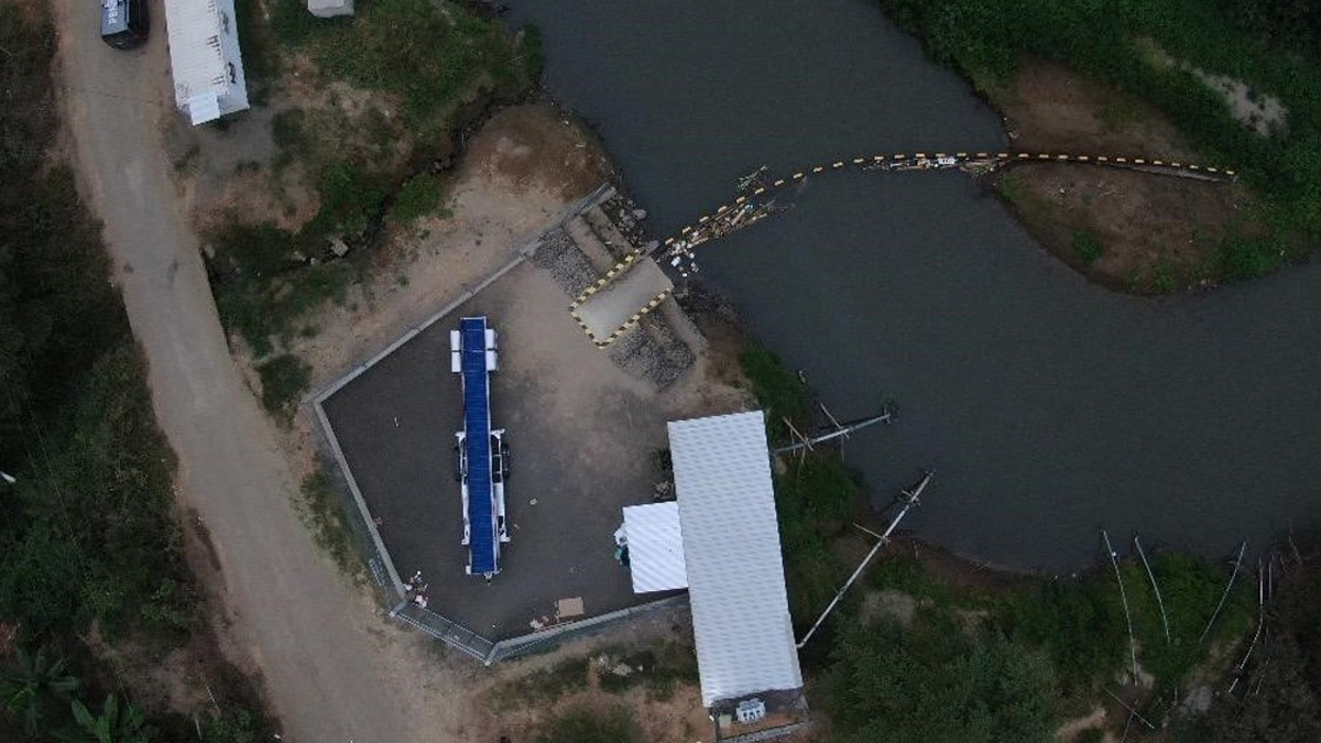
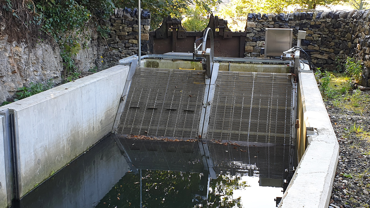
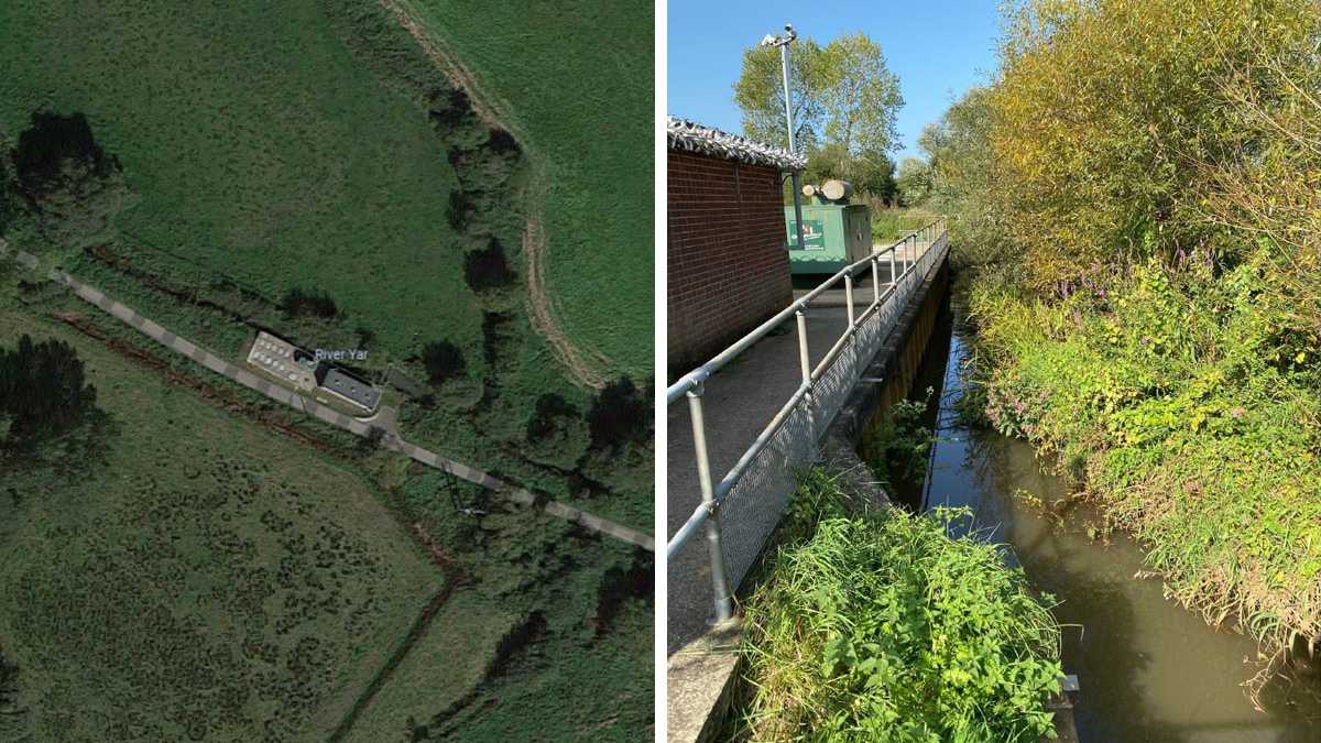
Intake location (underwater) with surrounding timber fender
Springfield Surface Water Abstraction (SWA) is a Southern Water pumping station located on the banks of the River Medway in Maidstone, Kent and transfers water to Eccles Lake. The intake is positioned flush with the riverbank and consists of two openings into an underground concrete intake structure, with a busy riverside towpath on top.
The picture above is before any works started. There are two coarse bar screens, one in front of each opening and a fixed timber boom in the river in front of the intake to deflect large debris. The flow travels approximately 25m by gravity into the pump house building, then is pumped to Eccles Lake and from there under gravity to Burham Water Supply Works.
To comply with The Eel Regulations, Southern Water had to upgrade the intake so that the maximum bar-spacing on the intake was 2 mm and the velocity of the water approaching the screen did not exceed 0.25 m/s. This is to prevent juvenile ‘glass eels’ from being sucked into the intake which would prevent them from moving upstream into the Medway catchment and beginning the long and complex life cycle of the European eel. The 0.25 m/s approach velocity could be achieved by using only half of the existing intake, with the other half blocked up using a concrete stop-log.
GoFlo Screens were awarded the contract to supply and assist with the installation of the eel screens at this location, by Trant/BTU Utilities Ltd.
The site is particularly complicated because it is in use 24/7, and cannot be turned off for more than a day or two before disruption to Burham Water Supply Works would occur. Coupled with this, the site cannot be de-watered, so would have to be installed by divers in water that is 4.5 metres deep, with very low underwater visibility.
The new GoFlo screens are too large to fit inside the existing concrete structure, so had to be accommodated outside of the existing concrete structure, in a prefabricated stainless steel ‘intake box’ that sits on the existing underwater concrete apron.
GoFlo designed and manufactured the GoFlo screens, intake box, walkways and debris trough. Everything had to be designed to be simple and modular so that the underwater elements could be installed by divers. The elements supplied by GoFlo are shown below along with the basic specification:
- Screen drive: 2.2 kW 3-phase WIMES-spec motor/gearbox
- Maximum bar spacing: 2mm
- (Single) screen mesh area: 4.652m2
- Angle of inclination (from horizontal): 72.5°
- Construction material: 304 stainless steel
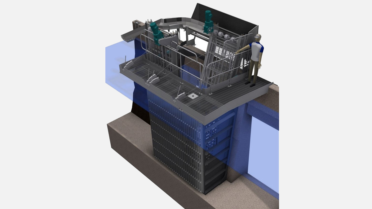
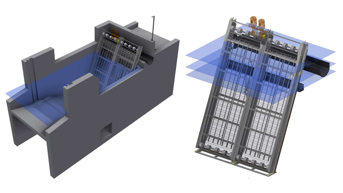
GoFlo 3D CAD model of the proposed screens, intake box and walkways
Proposed design
The overall design of the system was developed collaboratively between the main contractor (Trant/BTU), the client (Southern Water), Atkins Global who were the M&E designers working for Trant/BTU and GoFlo Screens. GoFlo also worked closely with Commercial and Specialised Diving Ltd to incorporate their ‘diver design friendly’ feedback into the design to make it easier for the divers to install, which was especially important considering it would be installed in the middle of winter.
Before the detailed design could begin, the intake and apron area in front had to be cleared of silt and debris. Once in the water the divers found a tangled mess of silt, fishing line, a large quantity of steel railing, two motorbikes, a pushbike and various other debris! Once the debris was cleared, a detailed site survey was undertaken to determine how flat the apron was, the exact profile of the vertical concrete piers which the GoFlo intake box would fix onto (a special 5-metre-long profile gauge was manufactured to achieve this), and check how far the apron extended out into the river. A number of differences were found between the original construction drawings from the 1960s and what was actually built. Following the site survey, a detailed 3D model of the intake was constructed in Inventor software which formed the basis of the GoFlo design.
The principle of the GoFlo design was a modular construction, comprising of:
- A fixing frame that fixed to the concrete structure and was used as a template for drilling the fixing holes.
- A sacrificial ‘measuring frame’ which bolted to the fixing frame to allow all of the key levels to be measured (hence adjusted) from above-water.
- 2 x intake box sides which bolted to the fixing frame (assembled above-water, after the fixing frame fixing holes had been drilled and the fixing frame removed).
- The standard GoFlo baseplate and pivoting frame (guide rails), 2 off.
- The standard GoFlo screen(s).
- Coarse debris screen/walkway that integrated with the Intake box/debris trough and return channel.
The modules were pre-assembled in our workshop to ensure that everything fitted together, prior to arrival on-site. The individual items, and the complete assembly are shown below.
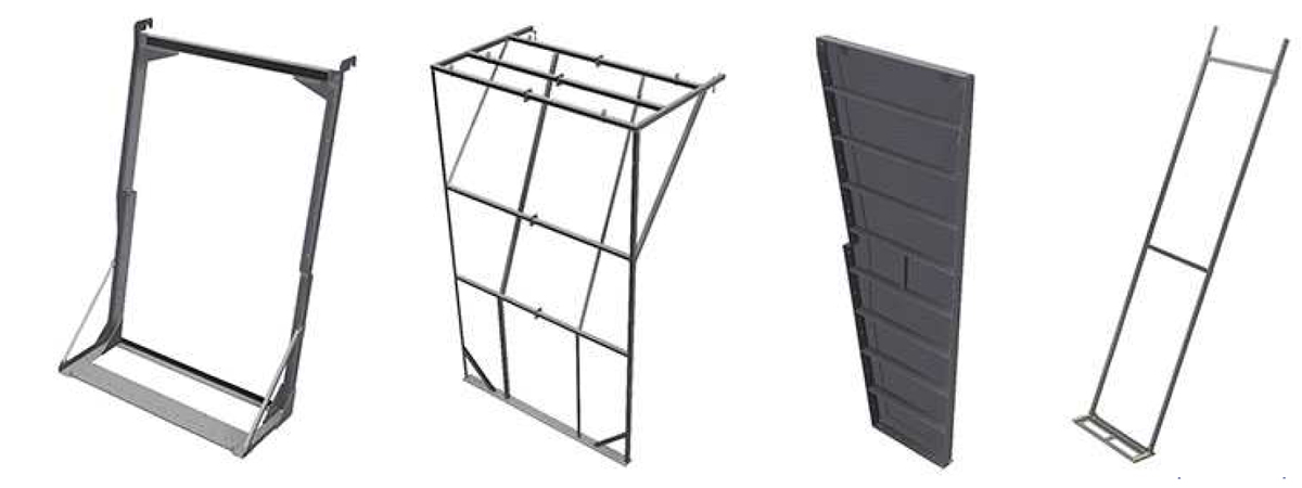
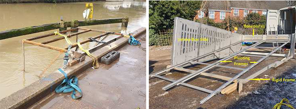
(i) The fixing frame (ii) the temporary measuring frame, fixed to the fixing frame (iii) an intake box side – two are required, and (iv) the baseplate and pivoting frame
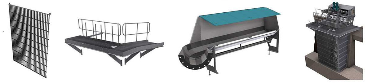
(i) Course debris screen (ii) the walkway assemblies (iii) debris trough and return channel with covers (iv) the completed design
The whole design was based on simplifying the works on site, particularly in regard to making the works as straightforward as possible for the divers. Key design features include:
- Two reference brackets installed on the above-water concrete upstand, which provided two precise reference points for the fixing frame to locate onto at top end.
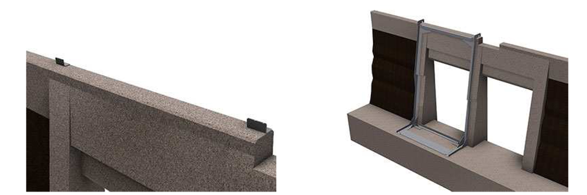
(left) Reference brackets fixed to existing concrete structure and (right) fixing frame in position against existing structure
- The fixing frame, which once positioned acted as a drilling template for all of the fixings into the concrete structure. At each fixing position there is an 18.5 mm diameter hole, to allow an 18 mm masonry drill bit to pass through which was used as a guide for drilling. These 18 mm diameter holes, once the fixing frame was removed, had Hilti HKD-SR stainless-steel M16 fixings installed.
- For precise positional adjustment, the fixing frame had 2 x M16 height adjusting bolts close to the toe of the intake apron, 2 x M16 stand-off adjusting bolts at the bottom of the vertical and two temporarily-fixed adjustment blocks at the bottom of the vertical frame members to allow the frame to be pushed/pulled both laterally and longitudinally, and once in position locked in that position for the fixings to be drilled. These were removed once the intake box was finally installed.
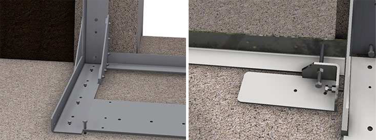
(left) Close up of the baseplate of the fixing frame, showing the levelling bolts and (right) temporary adjustment blocks used for positioning the fixing frame
- The fixing frame was designed to stand-off the concrete by a nominal distance of 20 mm to allow for unevenness in the concrete structure. This gap was taken-up at each fixing point using a stainless-steel shim stack. The height of the required shim stack was measured after the fixings holes had been drilled, but before the fixing frame was removed so that the shim stacks for each fixing point could be pre-prepared. Fine adjustment was still possible by adding/removing shims later as required.
- Once the fixing holes had been drilled, the fixing frame was removed, then the intake box sides bolted on, the GoFlo baseplates and pivoting frames attached. This allowed the whole intake box to be lifted in as an assembled unit and fixed in place using the pre-prepared fixings and shim stacks. Apart for the minor adjustments to levels, this saved a lot of complex underwater assembly work.
- Once the intake box was fixed in position, the coarse debris screen and walkway were fixed onto the intake box, then the GoFlo screens were installed.
So, that was the principle – now let’s looks at the actual installation!
Construction
The photos below show the actual parts being installed on site. Bear in mind that the water is 4.5 metres deep, and the GoFlo screen 6.1 metres long. The first photo shows the fixing frame lying on its back, having the measuring frame bolted to it prior to being lifted in. The second photo shows the assembled fixing frame and measuring frame being lifted into position. You can see that the river was very high after several days of heavy rain.
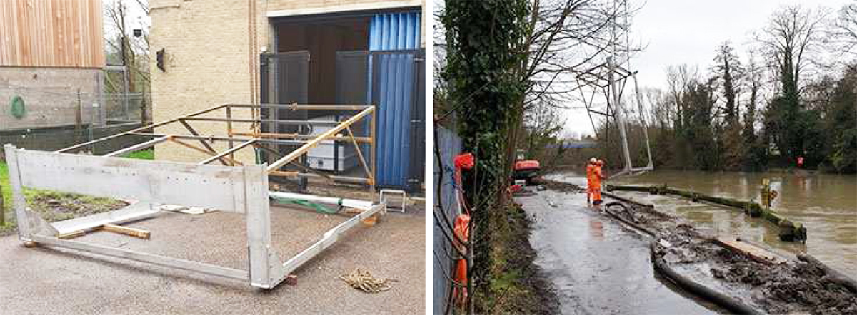
(left) Fixing frame and measuring frame being assembled and (right) fixing frame and measuring frame being lifted into the intake – note the very high water levels!
The fixing frame and measuring frame in position, ready for the fixing holes to be drilled. The mild steel measuring frame was sacrificial, but provided above-water horizontal references for a spirt level, which was essential during levelling.
Once the drilling was completed, the fixing frame and measuring frame were removed from the water, then the intake box sides, GoFlo screen baseplates and pivoting frames assembled together.
(left) Fixing frame and measuring frame in position and (right) the intake box being assembled prior to final installation
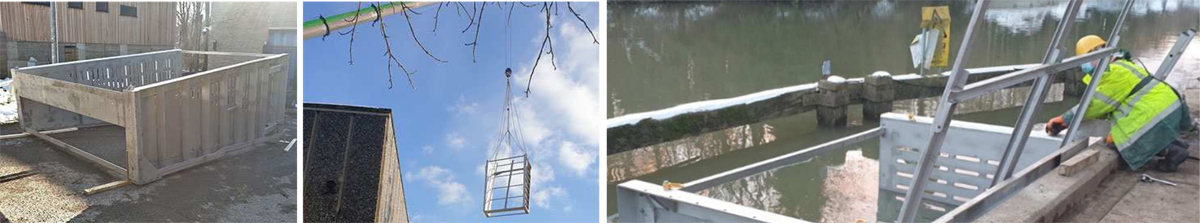
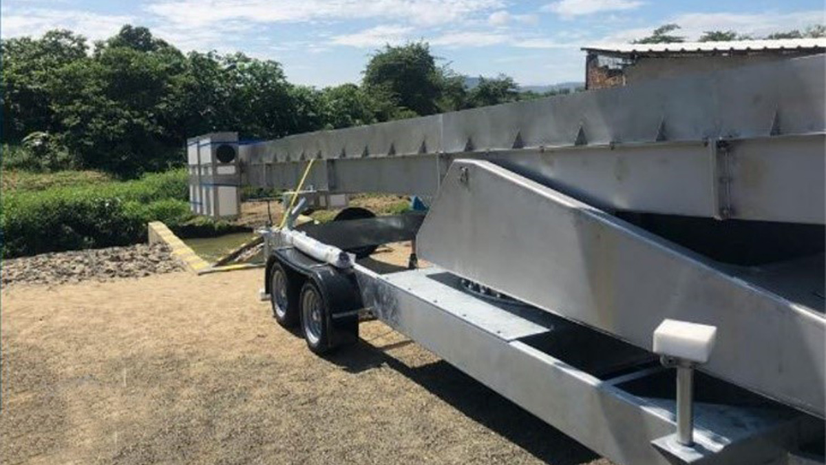
(left) The fully assembled intake box, (middle) lifting the assembled intake box into the intake with a 60-tonne crane, and (right) the assembled intake box was attached to the concrete structure by divers which took several days
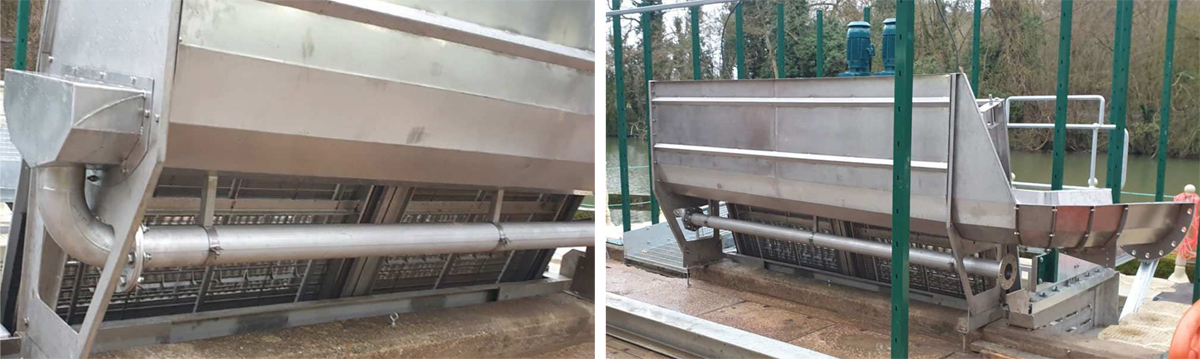
Next, the coarse bar screen was lifted into position, closely followed by the GoFlo Screens. GoFlo screens are lifted in vertically and use the pivoting frames as guide rails to guide the screen precisely onto the baseplate.
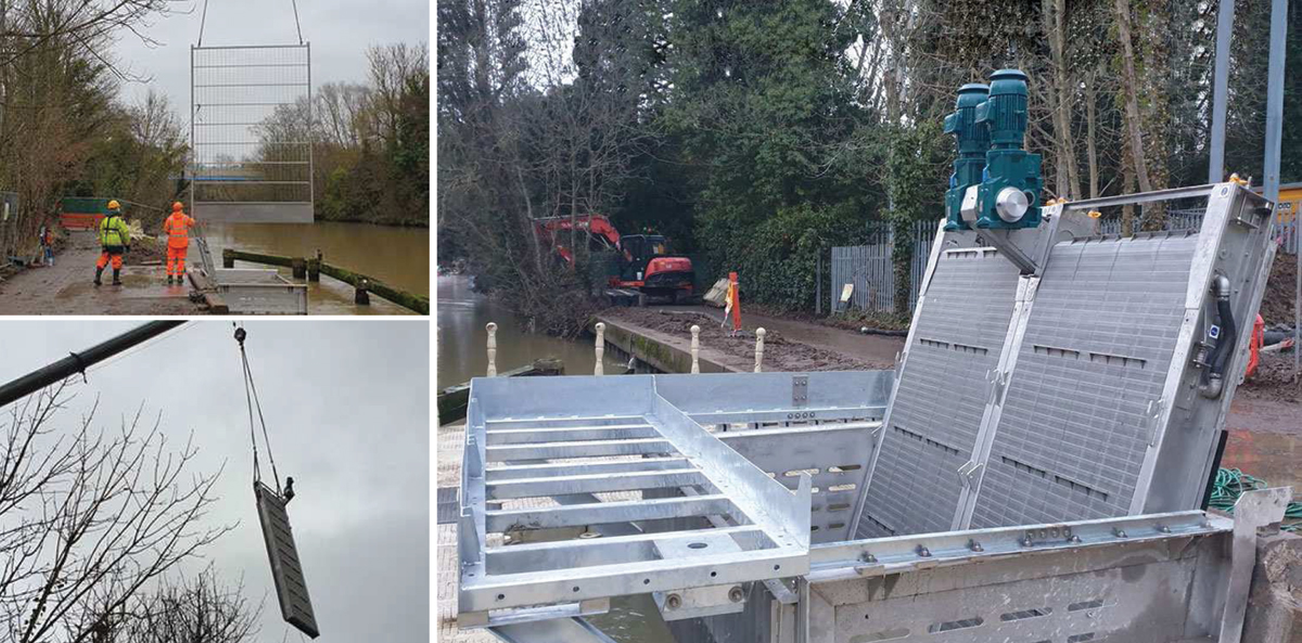
(top left) Lifting the course bar screen into the intake box, (bottom left) lifting the first GoFlo screen into the intake box, and (right) fitting the front part of the walkway structure onto the intake box
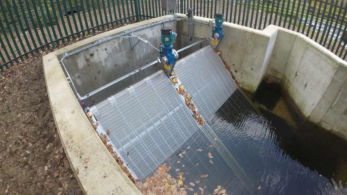
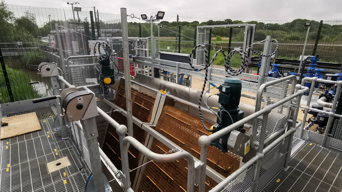
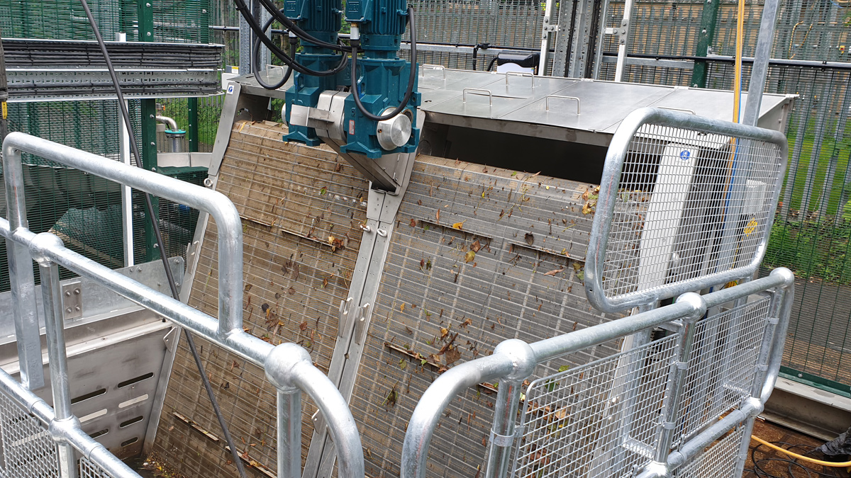
The screens are designed to discharge the collected debris into a dedicated trough behind the screens. The trough is made from stainless steel (as are the screens, intake box and coarse bar screen). The trough has a high back to catch the spray (2.5 bar water pressure) that is emitted from the screen spray-bars behind the mesh belt.
Each screen has a spray bar with multiple nozzles fed by a remote water booster pump located inside the main building. Debris on the surface of the screen mesh as it rotates falls off as it runs over the top sprockets, while any remaining ‘sticky’ debris is blasted off by water the jets from the inside of the screen and into the trough.
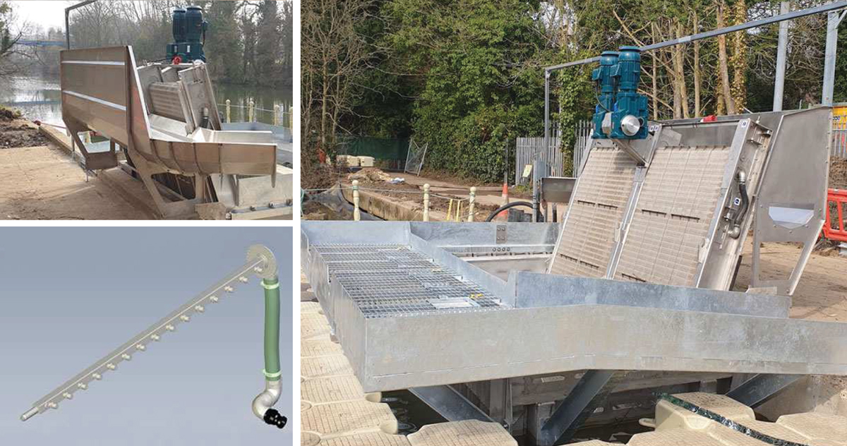
(top left) Fitting the debris trough and return channel, (bottom left) the spray boom assembly which fits inside the screen mesh, and (right) completed walkway structure attached to the intake box
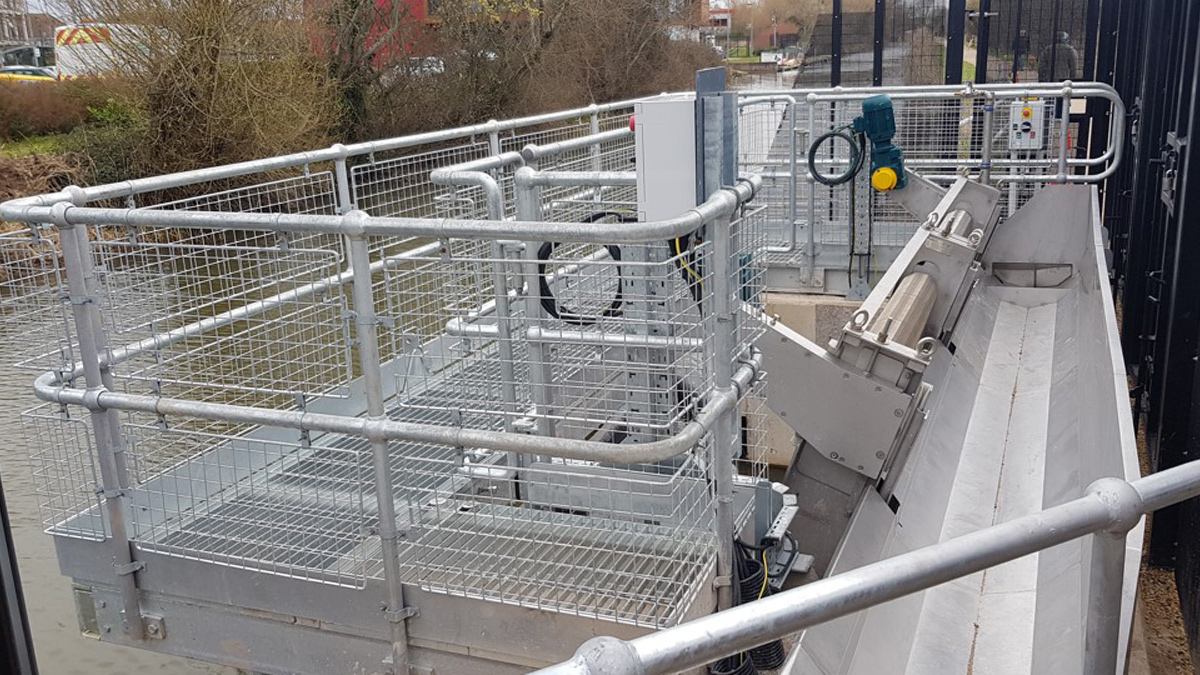
The debris trough includes a dedicated water feed (10 litres/second) to flush collected material back into the river downstream of the screens. The green fence posts are to support the security fence to protect the public from the machinery.
(left) The debris flushing flow pipework underneath the debris trough and (right) the security fencing being fitted
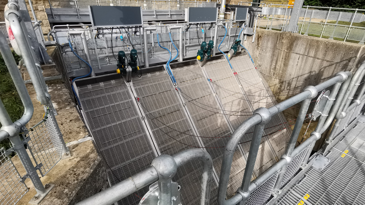
10 cm bar-spaced coarse debris screen protects the GoFlo screens from large object damage, and keeps swimmers out. Due to the proximity of the screens to the footpath and the possibility of ice formation in winter months, a fully enclosed debris trough was required to confine the spray mist. The covers are hinged to enable full unrestricted access to the trough.
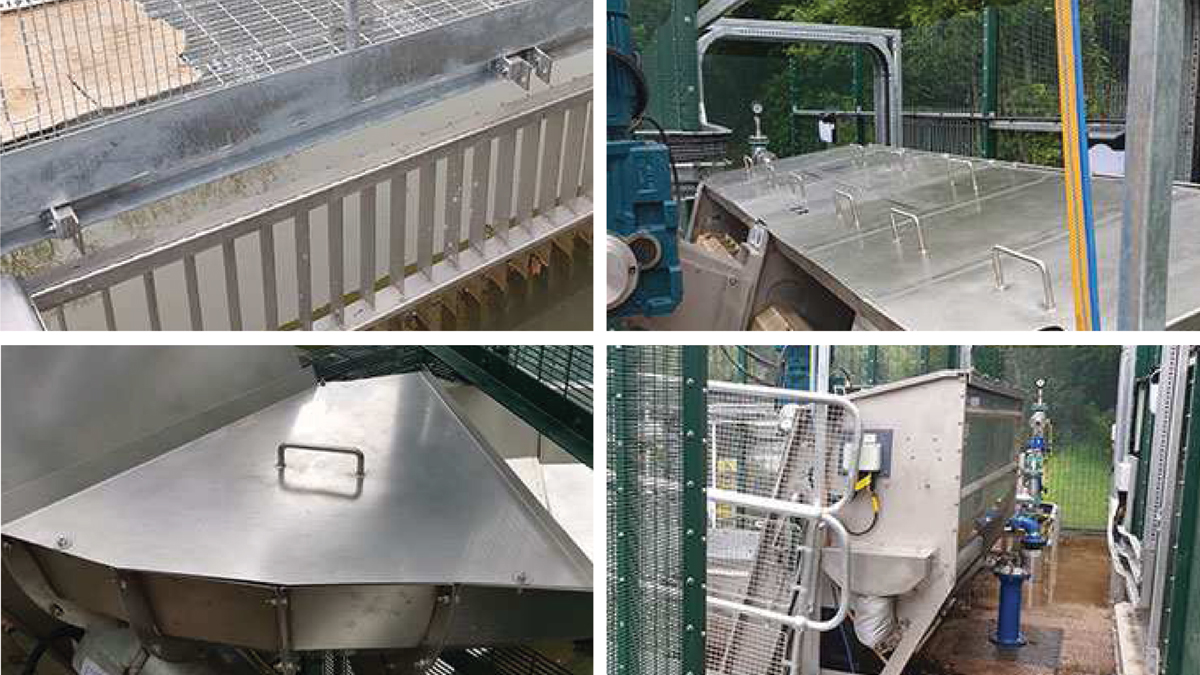
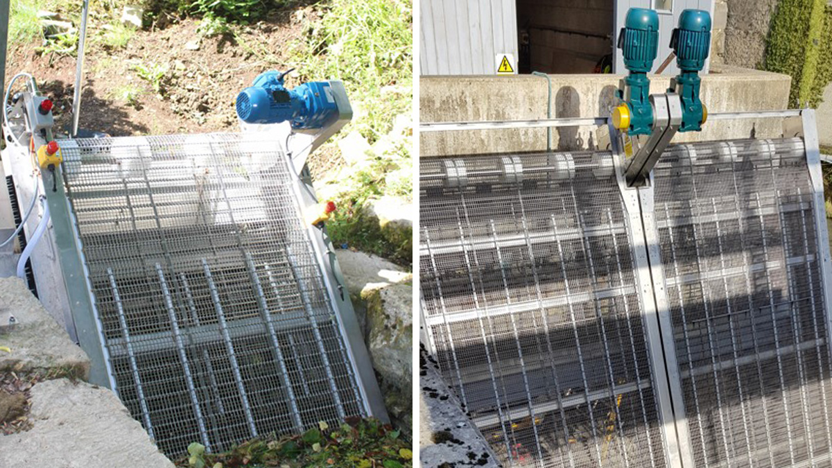
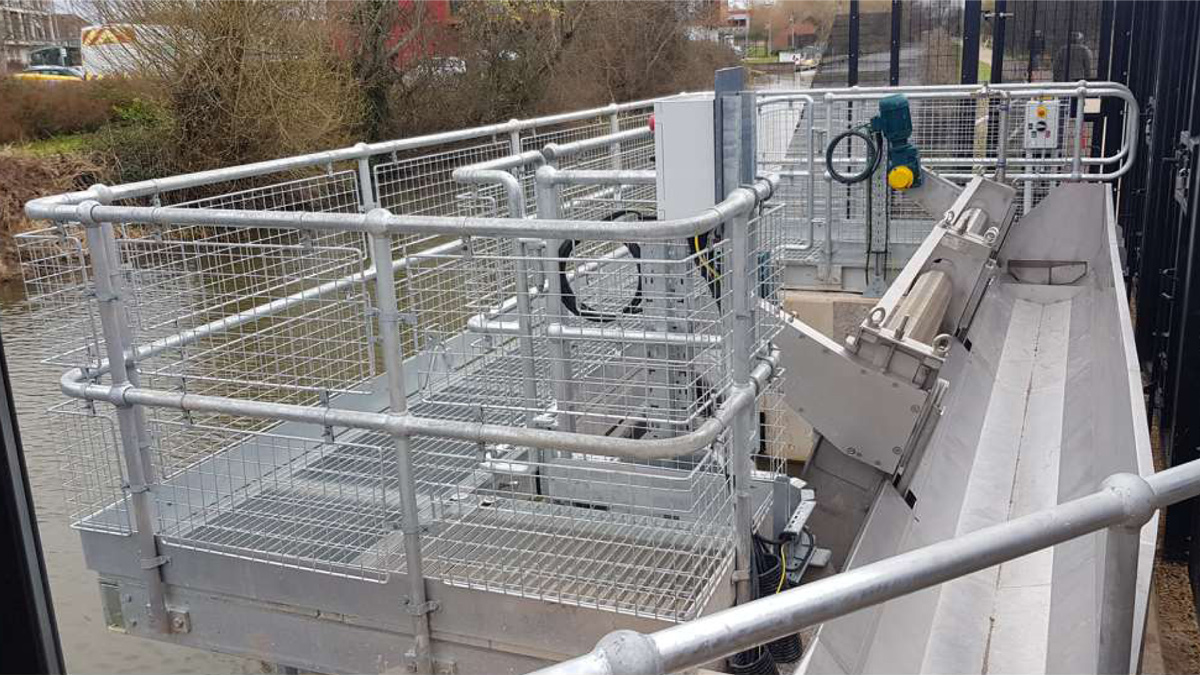
(top left) View from the-screens, looking out towards the river, (top right) the lids covering the debris trough, (bottom left) further lids covering the debris return channel and (bottom right) the completed installation, inside the security fencing
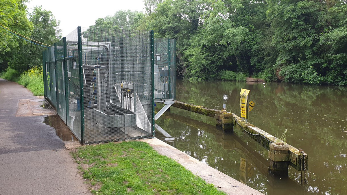
The completed installation, looking upstream
For more information: GoFlo Screens Ltd | +44 (0)1453 884400 | www.gofloscreens.co.uk
![]()
For More Information, contact us at http://www.gofloscreens.co.uk