
Pocklington STW (2026)
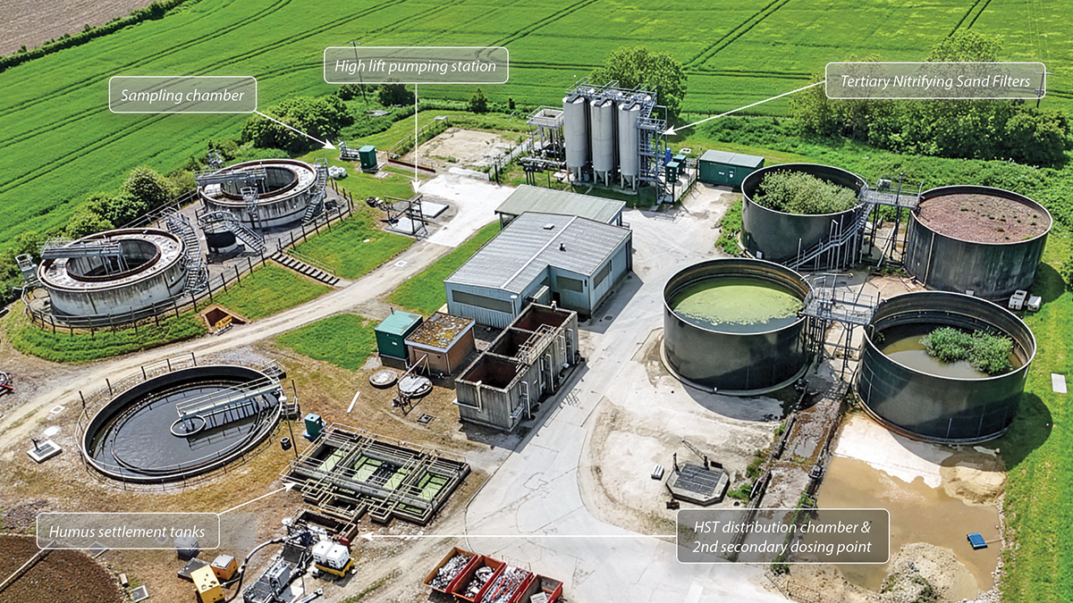
Overview of the Pocklington STW site - Courtesy of Enpure Ltd
Yorkshire Water’s Pocklington Sewage Treatment Works is located in the East Riding of Yorkshire. The site processes wastewater from the local catchment to safely return it to the environment, discharging treated effluent into the nearby Pocklington Beck. Yorkshire Water has delivered a £7.3m project to reduce the levels of phosphorus present in the treated wastewater returned to the environment and improve the water quality of more than 2km of the river downstream of the treatment works.
Project drivers
The AMP 7 WINEP drivers for Pocklington STW include a reduction in phosphorus and iron by December 2024 and a UIMP6 storm storage capacity increase by March 2025. The revised Environmental Agency Permits were:
| Parameter | Existing Value | New Value |
| Total P (annual average) | 1 mg/l | 0.25 mg/l |
| Iron (95%ile) | N/A | 4 mg/l |
| Iron (upper tier) | N/A | 8 mg/l |
| UIMP6 storm capacity | 658m3 | 766m3 |
Existing works
The existing works comprise a screened inlet arrangement incorporating grit removal and screenings handling, with flows conveyed by gravity to a storm overflow weir chamber. Under normal operation, the main flow passes to the primary settlement tank (PST) distribution chamber and is treated across three primary settlement tanks. Subsequent treatment proceeds through four trickling filters before discharge to the humus sludge handling system via a screw feed, and onward to dual humus tanks for secondary clarification. From here, clarified effluent is directed to a high-lift pumping station, which transfers flows to the tertiary nitrifying sand filter for final polishing. The treated effluent then passes through a sampling chamber prior to discharge to the receiving watercourse.
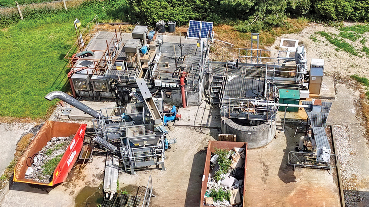
Inlet works – Courtesy of Enpure Ltd
Scope of works
The objective of the project was to achieve compliance with tightened phosphorus discharge consent in the final effluent, without breaching the revised total iron limits.
To meet these requirements, a comprehensive programme of process, mechanical, electrical, and civil upgrades was undertaken across the site, including the following key elements:
Chemical dosing
The existing chemical dosing kiosk was replaced with a new primary and secondary stage chemical storage and dosing system. This comprised twin internal storage tanks with a combined capacity of 20m³, together with duty/standby dosing pumps configured for automatic changeover. The installation included primary and secondary dosing lines with defined points of application, as well as associated safety infrastructure, including a safety shower.
Nitrifying sand filters
Refurbishment of the tertiary nitrifying sand filter (TNSF) system was carried out, including replacement of the process air compressors and decommissioning of the redundant process air blowers. The works also incorporated a new backwash pipeline and drainage chamber arrangement, complete with flow measurement, together with the provision of an additional washwater connection and hydrant.
High lift pumping station
Upgrades to the high-lift pumping station included the installation of new pumps and associated pipework, along with servicing and refurbishment of the existing bollfilter to ensure reliable downstream flow transfer to the tertiary treatment stage.
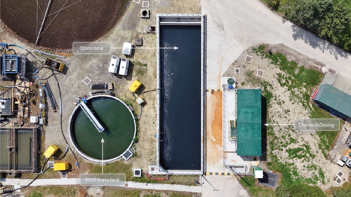
Overview of storm tanks and chemical dosing plant – Courtesy of Enpure Ltd
Storm capacity
The site’s storm storage capacity was increased from 658m³ to 766m³ through raising the coping levels of the existing tank walls and overflow weirs. In addition, structural modifications were undertaken to facilitate the replacement of the existing half-bridge scraper within the radial blind storm tank.
Electrical & control systems
Significant electrical and control system upgrades were also delivered. These included modification of the inlet works motor control centre (MCC) to accommodate the new dosing installation and scraper replacement, and upgrades to the sand filter kiosk MCCs to integrate the new TNSF equipment and allow for decommissioning of redundant assets.
Further works included modifications to all the MCCs by CEMA Ltd to enable integration into a new ethernet-based control network, installation of additional instrumentation and asset monitoring signals, and the provision of a new telemetry interface programmable logic controller (PLC) within the storm returns pumping station kiosk.
Ancillary works included the installation of site lighting to support new plant, process areas, and access routes, together with the associated electrical, control and instrumentation (EICA) systems necessary to support the upgraded infrastructure.
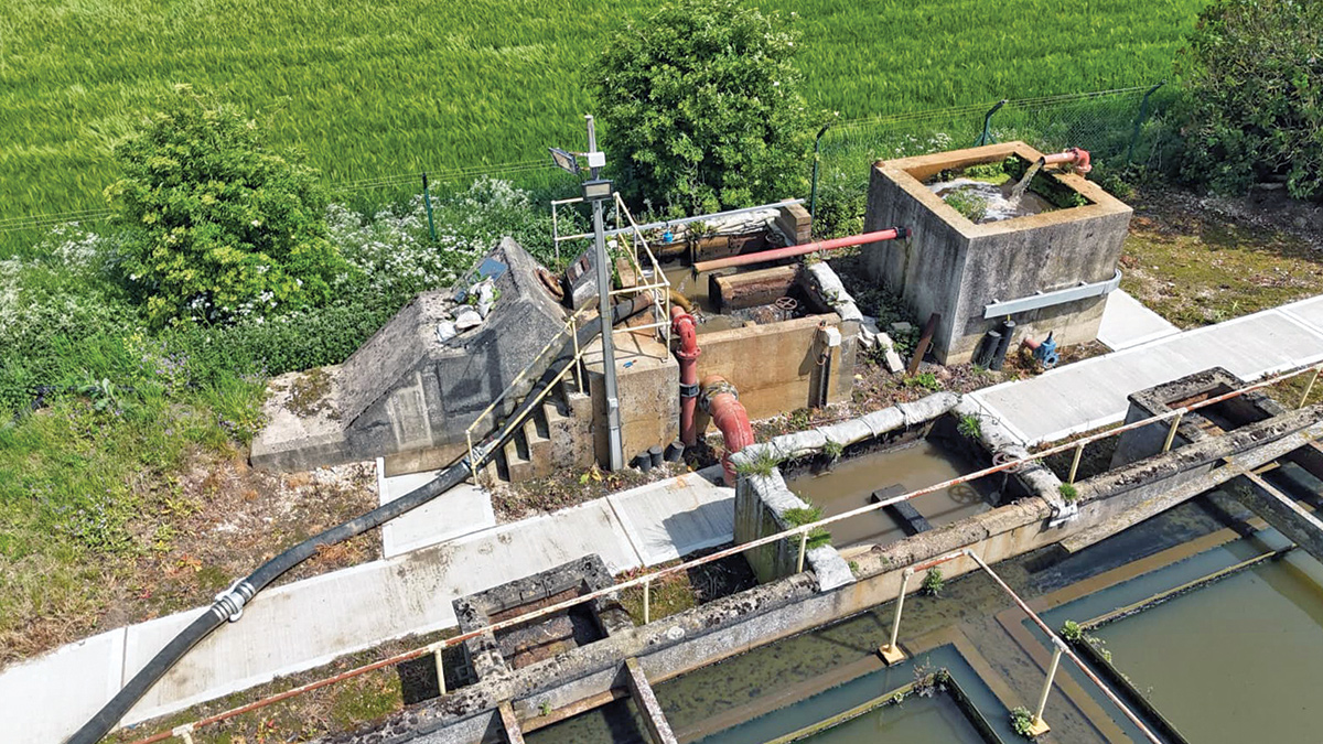
Primary settlement tank distribution chamber – Courtesy of Enpure Ltd
Pocklington STW: Supply chain – key participants
- Main designer & contractor: BEJV
- Civils: Barhale
- Process & M&E: Enpure Ltd
- Electrical installation: Circle Control
- Mechanical installation: JBF Group
- Mechanical installation: Tushingham Steel Fabricators Ltd
- MCCs, PLCs & SCADA: CEMA Ltd
- Ferric dosing: IIES (Northern) Ltd
- Kiosks: Morgan Marine Ltd
- Safety showers/eyebaths: Aqua Safety Showers International Ltd
- Tertiary nitrifying sand filters: Hydro International Ltd
- Scraper bridge refurbishment: WGM Engineering Ltd
- Pumps: Xylem Water Solutions
- Valves: Cotswold Valves Ltd
- Trace heating & lagging: Jade Insulation
- Flow meters & level transmitters: ABB
- Hose reels: ARCO Ltd
Inlet works
The existing works inlet consists of two Haigh Engineering screens complete with screenings handling and a grit removal system on the back end, which leads into the storm chamber.
Chemical dosing
To achieve compliance with the revised phosphorus discharge consent, implementation of both primary and secondary stage coagulant dosing was required. This was delivered via a purpose-built ferric dosing kiosk complete with integral chemical storage and a service water booster system. Given the nature of the chemical handling operations, a dedicated off-loading facility was also provided, comprising a bunded tanker delivery apron, an interlocked delivery point, and an emergency drench shower to meet safety and environmental requirements.
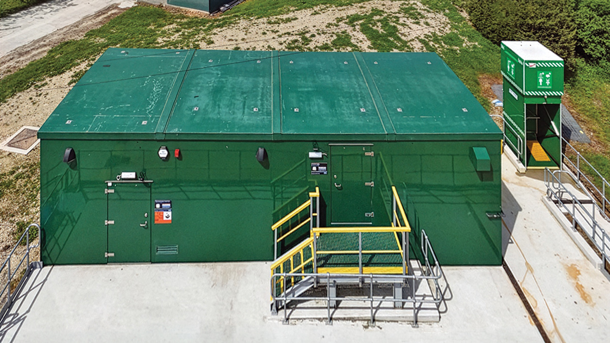
Chemical dosing kiosk and safety shower – Courtesy of Enpure Ltd
The new ferric storage and dosing installation was designed to provide sufficient capacity and dosing control to consistently achieve the required phosphorus removal performance. The system incorporates approximately 10 days of on-site chemical storage and was factory-tested prior to delivery to minimise site commissioning risk. The site layout and bunded delivery arrangement were configured to allow a ‘drive-in, drive-out’ tanker operation, improving both safety and operational efficiency.
The primary dosing system was initially configured to deliver coagulant into the primary settlement tank (PST) distribution chamber. However, following site-based process optimisation trials, the dosing point was relocated to the inlet works outlet chamber to improve mixing conditions and enhance phosphorus removal efficiency.
Secondary stage dosing locations were similarly subject to on-site trials to determine the most effective point of application. The preferred primary secondary dosing location was established at the base of the humus tank screw feed, with a secondary contingency dosing point provided at the existing HST distribution chamber. Both points of application were configured with duty/standby dosing arrangements and automatic changeover to ensure operational resilience and continuity of treatment performance.
Tertiary Nitrifying Sand Filter (TNSF)
The tertiary nitrifying sand filter operates on a counter-current flow principle. Influent water enters via a distribution system located at the base of the unit and is treated as it flows upward through the granular media bed, in this case sand, prior to discharge through the filtrate outlet at the top of the reactor.
Biological nitrification is achieved by autotrophic nitrifying bacteria colonising the media. To sustain this process, adequate oxygen transfer and carbon dioxide availability are essential. This is facilitated by aeration hoods positioned within the upper region of the media bed, supplied with process air to maintain optimal dissolved oxygen concentrations and promote effective ammonia oxidation to nitrate. The resulting nitrates remain in solution within the treated effluent.
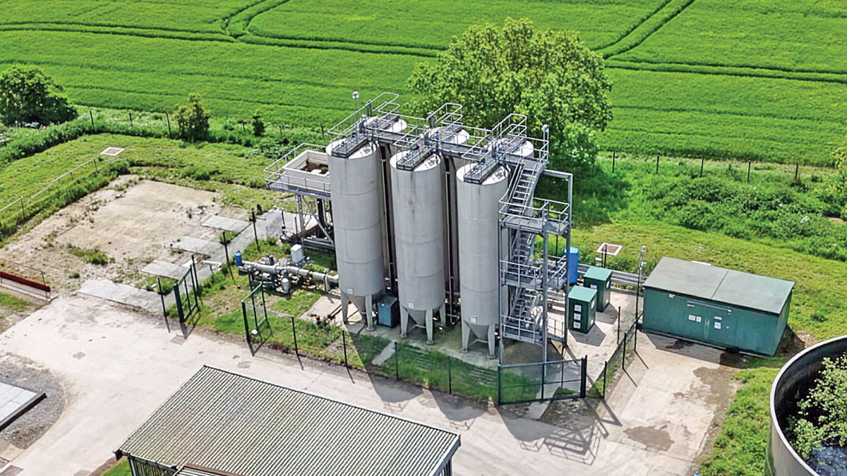
Tertiary nitrifying sand filter – Courtesy of Enpure Ltd
The media bed simultaneously functions as both a biological reactor and a physical filtration system, capturing suspended solids and biomass. To maintain treatment efficiency, the media undergoes continuous regeneration. Solids-laden media is drawn from the base of the unit via an airlift pump and conveyed to an integral media washing system located at the top of the filter.
Initial separation of impurities occurs within the airlift riser due to turbulent mixing. The media then discharges into a washing chamber (labyrinth), where it is subjected to a controlled counter-current flow of clean water. This process removes retained solids and sloughed biological growth.
The waste stream is discharged via the wash water outlet, while the denser, cleaned media is returned to the bed. This mechanism induces a slow, continuous downward movement of the media through the filter. Compressed air for the airlift system is supplied via a dedicated air distribution panel.
This continuous cycle of filtration and in situ media cleaning enables uninterrupted operation, eliminating the need for periodic backwashing and ensuring consistent treatment performance.
This element of the contract was awarded at an early stage whilst developing the remaining project scope. This approach allowed focused attention on this key component of the project, which involved confined space entry, along with a comprehensive condition assessment and overhaul of an existing, previously disused asset. This strategy also supported carbon savings and contributed to the circular economy.
The existing TNSF units were refurbished as part of the works. BEJV engaged Hydro International to deliver key process upgrades, including the supply and installation of two new compressors with acoustic enclosures, replacement filter media, full renewal of internal pipework, and system commissioning to restore operational performance and reliability.
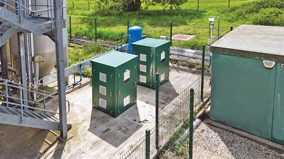
TNSF compressors – Courtesy of Enpure Ltd
Storm tanks
The original project scope proposed refurbishment of the existing storm tank, alongside the provision of additional capacity by increasing the coping level of the adjacent square storm tank.
However, during inspection under dry weather flow conditions, it became evident that the existing storm tank had deteriorated beyond economical repair due to its age and original construction. Consequently, the agreed solution was to demolish the existing structure and construct a new tank within the same footprint.
To maintain compliance with the site’s storm storage permit throughout the construction period, a temporary strategy was implemented. This comprised both temporary over-pumping arrangements and interim storm storage provision.
These works introduced additional logistical and operational constraints, including the requirement to secure temporary access to adjacent third-party land to accommodate temporary storm tanks while demolition and reconstruction activities were undertaken.
In addition, a separate ‘blind’ storm tank was incorporated into the overall strategy to supplement storm storage capacity. The initial scope included replacement of the existing scraper bridge and removal of the launder troughs, however, following a detailed condition assessment, the existing assets were found to be structurally sound and suitable for refurbishment.
The adopted solution involved raising the scraper bridge by approximately 300mm and applying a protective re-coating system. This approach delivered a cost saving of approximately £50,000 to the client while maintaining operational performance and extending asset life.
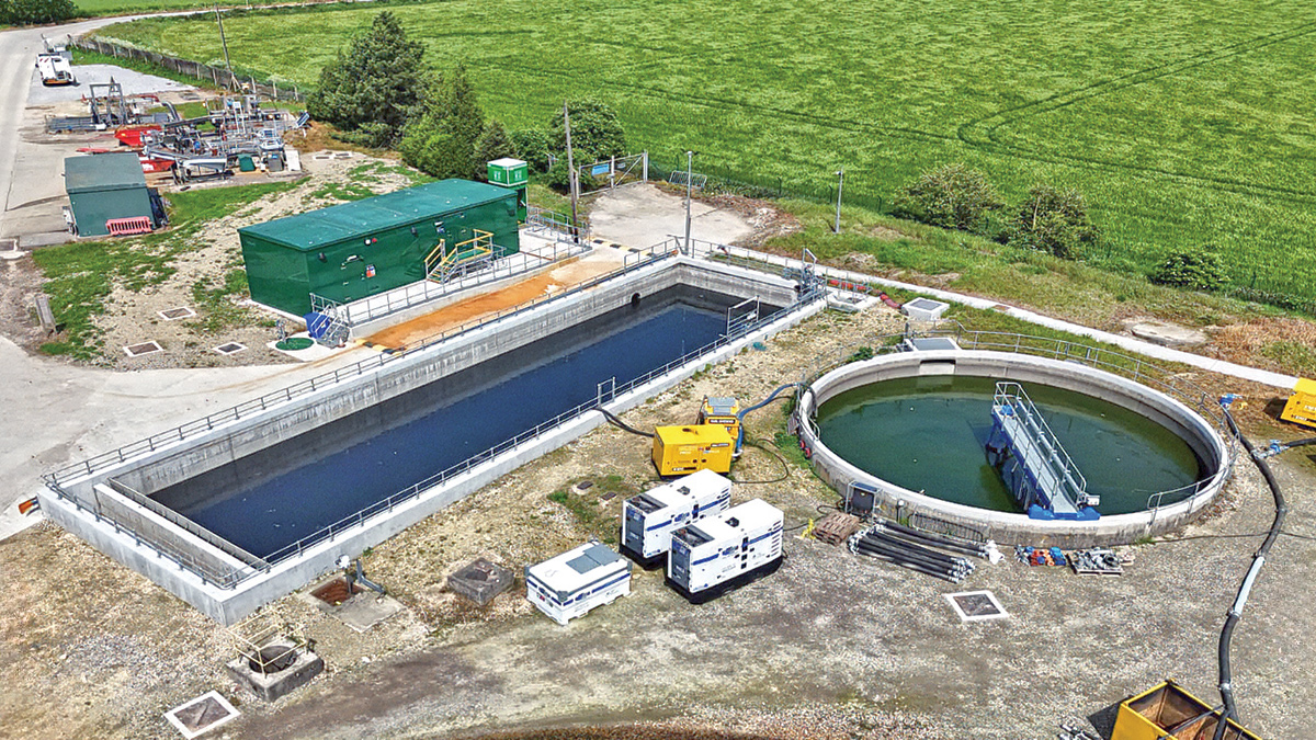
Storm tanks – Courtesy of Enpure Ltd
Status
The upgraded works at Pocklington STW successfully met the regulatory compliance date, with all process-critical improvements completed by 31 March 2025. The overall project was subsequently finalised in March 2026 following the completion of additional works.
This scheme has significantly enhanced the treatment capability for incoming raw water, while stabilising throughput and increasing operational resilience. As a result, it delivers a robust and sustainable improvement to the local Yorkshire Water network, providing long-term benefits for the communities it serves.
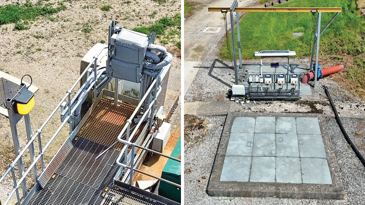
(left) Ferric primary dosing position and (right) high lift pumping station - Courtesy of Enpure Ltd