

Shoscombe WRC (2026)
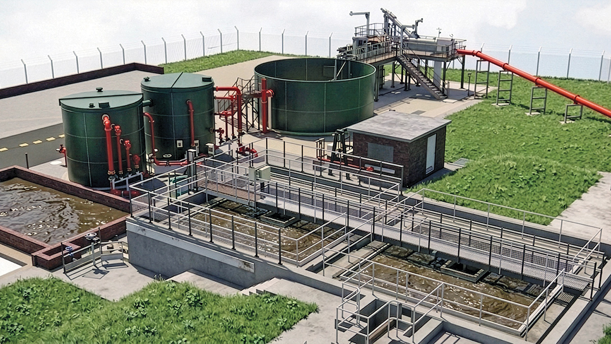
Model of the completed Shoscombe upgrade - Courtesy of BIMTek Limited
Shoscombe Water Recycling Centre (WRC) is situated around 7km south of Bath and serves the rural parish of Shoscombe and its surrounding catchment. The population equivalent (PE) for the area is projected to surpass 2,000 by 2030; a threshold that triggers stricter regulatory requirements for monitoring, reporting, and environmental compliance. The site lies adjacent to the historic Shoscombe and Single Hill railway station, which operated between 1929 and 1966. This historical context contributes to the site’s unique rural character, combining heritage with a tranquil countryside setting and a close-knit community identity.
Background
Originally constructed during the 1970s, the WRC infrastructure has not evolved sufficiently to accommodate ongoing population growth and tightening environmental standards. Prior to the upgrade works, the existing treatment process consisted of an inlet channel, a duty screen, and a flow measurement flume. Primary treatment was delivered via two primary settlement tanks equipped with desludging systems, followed by secondary treatment through two biological filters and a single humus tank. The site also included two sludge storage tanks and a water recycling pumping station (WRPS) that managed internal drainage and return flows.
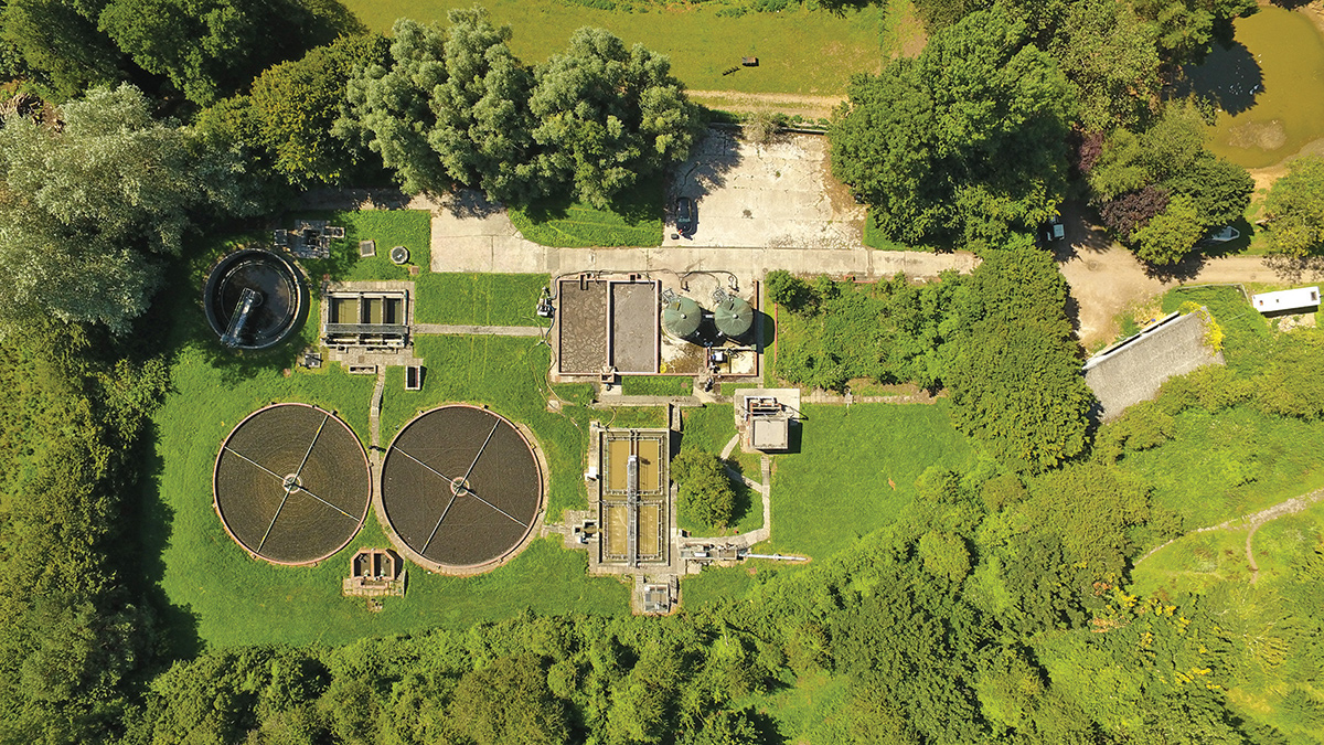
Shoscombe WRC pre-upgrades – Courtesy of BIMTek Ltd
Although relatively small in scale, the upgrade scheme represented a significant infrastructure investment. The project posed multiple logistical and technical challenges, including restricted vehicular access, limited working space, constrained material storage areas, and incoming water main for site welfare facilities. These constraints required careful planning and a collaborative delivery strategy.
The project ultimately demonstrated best practice in areas such as design development, LiDAR-based site modelling, prefabricated component integration, electrical and control engineering and multidisciplinary coordination across engineering teams.
Project drivers
The upgrade programme was driven by both AMP7 and AMP8 regulatory commitments, ensuring continuity of delivery teams on site throughout the scheme lifecycle.
The AMP7 works were scheduled for completion by 31 March 2026, while the AMP8 phosphorus removal requirements must be met by March 2030.
The PR24 Water Industry National Environment Programme (WINEP) identified Shoscombe WRC as requiring phosphorus removal enhancements during AMP8. In addition, AMP7 identified the need for increased pass forward flow (PFF) capacity and increased storm storage to meet future demand and environmental standards. The principal drivers behind the scheme included:
- Compliance with updated discharge permits.
- Improvement of receiving watercourse quality.
- Alignment with the Environment Agency’s Environmental Performance Assessment targets.
- Delivery of WINEP obligations within defined regulatory timelines.
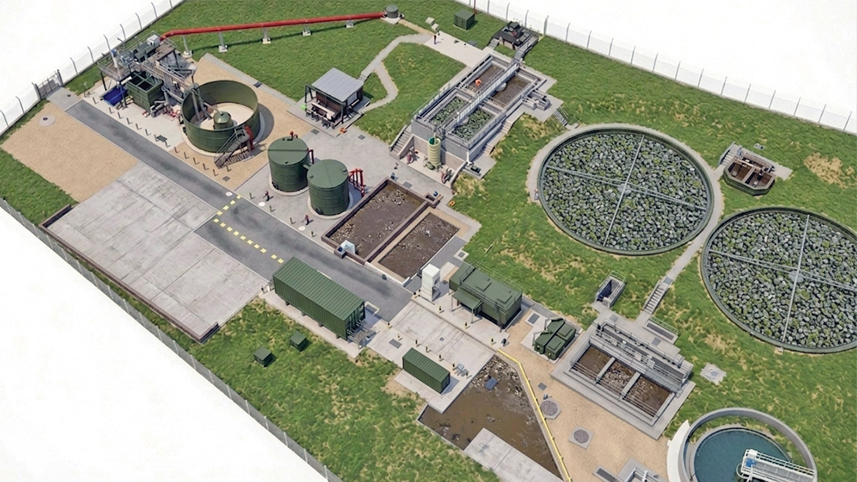
Model showing the new assets at Shoscombe WRC once upgrades are complete – Courtesy of BIMTek Ltd
AMP7 Scope
Flow Increase: A revised dry weather flow (DWF) permit of 308 m3/day was established, providing sufficient capacity for growth beyond 2040. The full flow to treatment (FFT) was increased from 10 l/s to 18 l/s.
New Inlet Infrastructure: A new offline inlet arrangement was constructed, including:
- A dedicated grit removal chamber.
- A new Huber Technology Ro9 rag removal screening unit with integrated bypass.
- A prefabricated pumping station with a hydraulically safe overflow connection to storm storage.
- Installation of event duration monitoring (EDM) equipment to meet UMON3 & UMON1 requirements.
Storm Storage Expansion: The updated DWF permit required storm storage capacity to increase from 48m3 to 165m3, which will significantly improve resilience during peak flow conditions.
Electrical Infrastructure: A mains incomer linked to a new DNO supply was delivered including a new motor control centre (MCC), a high-voltage transformer (installed during Phase 1), and a 100kVA standby diesel generator with bunded containment.
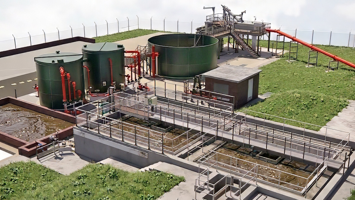
Model showing the new assets at Shoscombe WRC once upgrades are complete – Courtesy of BIMTek Ltd
AMP8 Scope
Phosphorus removal: A chemical dosing system comprising:
- 10m3 bulk ferric sulphate storage capacity & dosing skid.
- Front-end dosing equipment with leak detection.
- A dedicated dosing chamber and kiosk.
- Delivery bund with interlock valve system
Sludge storage upgrade:
- Two 60m3 glass-fused-to-steel (GFS) sludge tanks.
- Addition of decant systems and dewatering pipework.
- Replacing the existing tanks and associated infrastructure.
- A new hydraulically safe combined sludge transfer pumping system for both automatic and manual desludge maintenance.
| Parameter | Current Permit | AMP7 Permit | AMP8 Permit | AMP8 Regulation Date |
| DWF | 505 m3/d | 308 m3/d | No change | n/a |
| FPF | 10 l/s | 18 l/s | No change | n/a |
| Sorm Storage | 48 m3 | 165 m3 | No change | n/a |
| BOD | 30 mg/l | No change | No change | n/a |
| Suspended Solids | 70 mg/l | No change | No change | n/a |
| Ammonia (95%ile) | 15 mg/l | No change | No change | n/a |
| Phosphorus | None | None | 1 mg/l | 31 March 2030 |
| Iron (95% | upper limit) | None | None | 4 mg/l | 8 mg/l | 31 March 2030 |
| UWwTD: BOD (95&ile) | None | None | 25 mg/l | 13 May 2030 |
| UWwTD: COD (95%ile) | None | None | 125 mg/l | 13 May 2030 |
| Permit limit summary – Courtesy of BIMTek Ltd | ||||
Solution development
Initial buildability assessments highlighted several constraints that required consideration following site inspections. While access gradients were less restrictive than anticipated, proximity to boundary fencing posed challenges for piling operations. Restricted working space along the inlet boundary raised concerns regarding both temporary and permanent works, necessitating consultation with specialist contractors.
Structural considerations included verification and monitoring of retaining wall integrity due to increased traffic. Temporary works planning was particularly complex due to confined areas around existing infrastructure, especially near the LV pole and temporary Ro9 configuration.

Retaining wall bridge monitoring targets – Courtesy of BIMTek Ltd
Further challenges included limited working space around the new storm tank footprint, the proximity of the rising mains to existing retaining structures, and the condition of the access track, which was unsuitable for standard construction vehicles.
A revised design approach was therefore developed, relocating key infrastructure to an offline roadside position. This alternative solution improved constructability, reduced operational risk, and mitigated access constraints.
Shoscombe WRC: Supply chain – key participants
- Project delivery: YTL Construction
- Process design: Wessex Water
- Civil & mechanical design: BIMTek Ltd
- Electrical/ICA control system modifications, MCCs & kiosks: BW Controls
- M&E & civils contractor: K Gregory Construction Ltd
- Ferric dosing: WES Ltd
- PP ferric chamber: Moor Fabrications Plastics Ltd
- Safety shower: Aqua Safety Showers International Ltd
- GFS sludge tanks: Hayes GFS Ltd
- Storm tank: Goodwin Tanks Ltd
- Storm tank flushing bell: Eliquo Hydrok Ltd
- Level & flow instrumentation: VEGA Controls Ltd
- IQ3 Pro actuator replacement: Tork Site Services Ltd
- Instrument calibration: Rhopoint Metrology Ltd
- PE pipe: Westwood Pipelines Ltd t/a egeplast UK
- DI pipe: Saint Gobain PAM UK
- Pipes: Pipes & Valves Ltd
- Trace heating & lagging: Jade Insulation
- Galvanised joint set: Stark Group t/a Jewson Civils Frazer
- Inlet screens: Huber Technology
- Pumps: Xylem Water Solutions
- Desludge chamber: NOV – Fibre Glass System
- Lift chain: Grundfos Pumps Ltd
- Lifting equipment & davit systems: REID Lifting
- Crane hire & lifting: MB Crane Hire
- Hydro demolition & jetting: Sabre Jetting Services Ltd
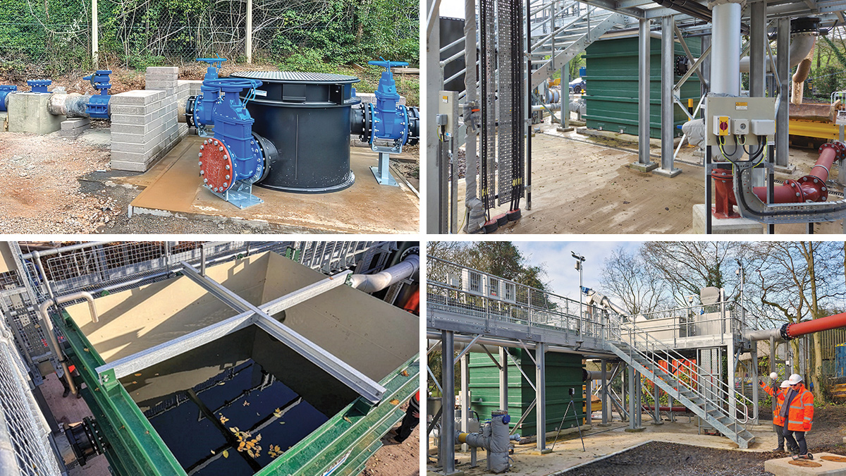
(top left) Inlet diversion chamber with temporary bypass pipework, (bottom left) plastic inlet pumping station, and (right) inlet pumping station & GMS platform – Courtesy of BIMTek Ltd
Work methods
Preparatory works included completion of the HV electrical upgrade and restoration of the site access track using compacted gravel. A new water supply pipeline was scheduled ahead of main construction activities. Due to uncertainty around connection timing, temporary water provision was maintained using intermediate bulk containers (IBCs) to support welfare facilities.
Close collaboration was maintained with the construction team to develop safe and practical temporary works solutions. Key sequencing considerations included:
- Commissioning of the new MCC before decommissioning the existing system.
- Installing and commissioning new infrastructure prior to isolating existing assets.
- Diverting incoming flow during low flow periods.
- Minimising overpumping.
Project timeline
| Phase | Date | Key Activities | ||
| Phase 1 | November 2023 | Installation of 600m HV supply line and transformer pole upgrade. Flood risk assessment completed. | ||
| Phase 2 | November 2024 | Installation of a new Bristol Water main along entrance access track. | ||
| Phase 3 | March 2025 | Delivery of AMP7 main upgrade works. Ecology and environmental surveys. Repairs to access retaining wall. | ||
| Phase 4 | March 2026 | Delivery of AMP8 phosphorus removal and sludge tank upgrades. | ||
Construction
Inlet works
The existing inlet works remained fully operational throughout the construction period. Most of the new infrastructure was delivered offline within the footprint of the former sludge drying beds at the lower end of the site. Construction commenced with the breakout and removal of existing concrete foundations, followed by significant excavation works to achieve the required formation levels for the new structures.
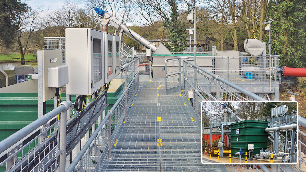
Grit trap and Ro9 rag removal screening unit and (inset) the inlet pumping station & GMS platform – Courtesy of BIMTek Ltd
A prefabricated diversion chamber supplied by NOV Pipex was installed on the incoming sewer to facilitate the future transfer of flows to the new inlet works during commissioning. Once the new inlet arrangement was brought into service, the original inlet works were decommissioned and demolished, and the area was backfilled to reinstate existing ground levels.
A reinforced concrete base slab, incorporating a central ACO drainage channel, was constructed to support the new inlet. The DN350 inlet sewer was diverted to discharge into a new elevated inlet structure. Dedicated pipe supports with in-situ concrete foundations were also installed.
The new inlet pumping station was constructed on a purpose-built base. To improve site access and drainage, a new tarmac access road and associated surface water gullies were installed. A new lighting system was also installed to ensure safe access for operation and maintenance activities on the inlet platform.
Storm storage tank
To meet increased storage requirements, a new above-ground GFS tank with a capacity of 165m3 was installed. The tank, measuring 8.5m in diameter, incorporated connections including inlet overflow, return pipework, and outfall linked to a V-notch weir chamber for settled storm sampling. Additional features included:
- An automatic flushing bell system for sediment management.
- A storm return pumping arrangement.
- A new sampling point with safe access provisions.
Construction commenced with base slab installation, with the first concrete pour completed in June 2025.
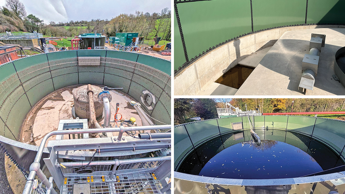
(left) Storm tank flushing bell from Eliquo Hydrok Ltd, (top right) inside the new above-ground GFS storm tank from Goodwin Tanks Ltd and (bottom right) storm tank hydrostatic testing – Courtesy of BIMTek Ltd
At the request of the contractor, an unconventional vertical pour methodology was developed, which required careful detailing of reinforcing continuity and waterproofing. The storm tank construction methodology was as follows:
- Sump base slab: Cast with starter reinforcing and integrated waterstops.
- Sump wall construction: With additional cast-in waterstops.
- Upper circular foundation preparation: Full circular base preparation for phased slab pour.
- Central flat slab structure: Central flat slab constructed with waterstops and pull-out continuity bars.
- Sloped second slab structure: Poured to falls, again with waterstops and continuity bars.
- Outer ring-beam construction: Circular pour to form the ring-beam supporting the tank structure.
- Channel infill: Pouring of the inner drainage channel to falls, using low-shrink concrete and waterstops.
Phosphorus removal
A ferric sulphate dosing system supplied by WES Ltd was installed to facilitate phosphorus removal in accordance with AMP8 requirements. The installation comprised a 10m³ integrated chemical storage tank, dosing pumps and a control panel, all housed within a dedicated kiosk.
To provide secondary containment, a reinforced concrete bund was constructed, with drainage connected to the existing site network. Additional reinforced concrete slabs were installed to support both the dosing kiosk and an adjacent emergency safety shower.
The delivery and installation of the dosing unit presented several logistical challenges due to restricted access at the site entrance. Despite these constraints, the unit was successfully lifted into position using a HIAB crane. Given the substantial weight of the equipment and the limited slewing space available at the installation location, the lifting operation was carefully planned and coordinated to ensure its safe and precise placement onto the prepared foundation slab.
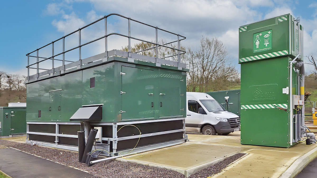
Kiosk and safety shower – Courtesy of BIMTek Ltd
Motor control centre (MCC)
The MCC was delivered as a prefabricated off-site solution and installed on a raised structural steel platform, providing enhanced flood resilience and improved operational access. Following installation, a flat-pack kiosk enclosure was assembled around the MCC to provide environmental protection and secure housing for the electrical equipment.
The new system was supplied via a dedicated mains incomer connected to the DNO network through the high-voltage transformer installed during Phase 1 of the project. To maintain uninterrupted site operations, the existing electrical infrastructure remained live throughout the installation and commissioning period, ensuring continuity of service until the new MCC was fully operational.
During the design and construction phases, existing power supplies serving neighbouring assets, including a nearby farm building, were identified and programmed for diversion beyond the operational boundary. Associated trenching and cable diversion works were carefully planned and coordinated with both the construction team and National Grid to minimise disruption and ensure programme alignment.
The final changeover to the new electrical system was scheduled only after the completion of all commissioning, testing and performance verification activities. This phased approach reduced operational risk and ensured a resilient and seamless transition to the upgraded infrastructure.
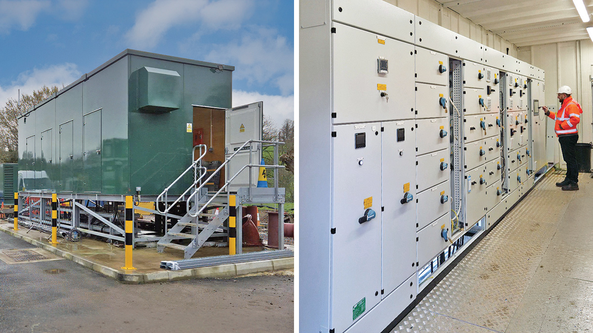
Elevated kiosk & MCC – Courtesy of BIMTek Ltd
Sludge storage
The existing sludge storage facility was assessed and deemed unsuitable for refurbishment due to structural deficiencies, condemned access arrangements and limited long-term maintainability. To meet current operational, safety and asset management requirements, the existing infrastructure was replaced with new glass-fused-to-steel (GFS) sludge storage tanks
The existing tanks and associated steelwork were carefully dismantled and removed. The tank bases were then cleaned, inspected and prepared for reuse, including hydro-demolition works and the formation of rebates for new fixings. Throughout construction, the existing desludging system remained operational to maintain continuity of treatment.
A new offline desludge pumping system was installed, comprising duty and standby pumps mounted on a reinforced concrete plinth complete with valve assemblies and maintenance lifting provisions. A hydraulically safe control chamber was also constructed on reinforced concrete foundations to accommodate actuated controls and associated equipment.
The scheme included upgrades to local drainage, installation of new rising mains, bypass pipework and a dedicated jetting point, together with ducting, control cabling, instrumentation and monitoring systems. Trace-heated and insulated pipework was provided to ensure reliable operation during cold weather conditions.
Final works included the installation of control panels, actuator systems and provision for a future acoustic enclosure to support potential noise reduction requirements.
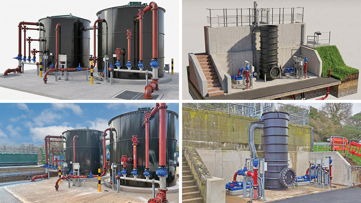
Model and as-built images: (left) the 60m3 sludge tanks and (right) the combined sludge transfer PS – Courtesy of BIMTek Ltd
Summary
The Shoscombe WRC upgrade represents a comprehensive and technically challenging infrastructure project delivered within a constrained rural environment. The scheme successfully addressed regulatory requirements for flow capacity, storm storage, and phosphorus removal, while maintaining continuous site operation throughout construction.
Through innovative design, off-site fabrication, and collaborative working practices, the project team overcame logistical and engineering challenges to deliver a future-ready treatment facility. The upgraded works will significantly improve environmental performance, ensuring compliance with evolving standards and contributing to enhanced water quality in the receiving environment.
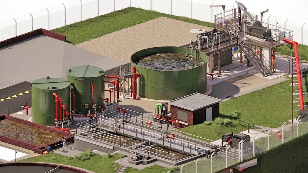
Model showing the new assets at Shoscombe WRC once upgrades complete - Courtesy of BIMTek Limited