Basingstoke Sludge Treatment Centre (2017)
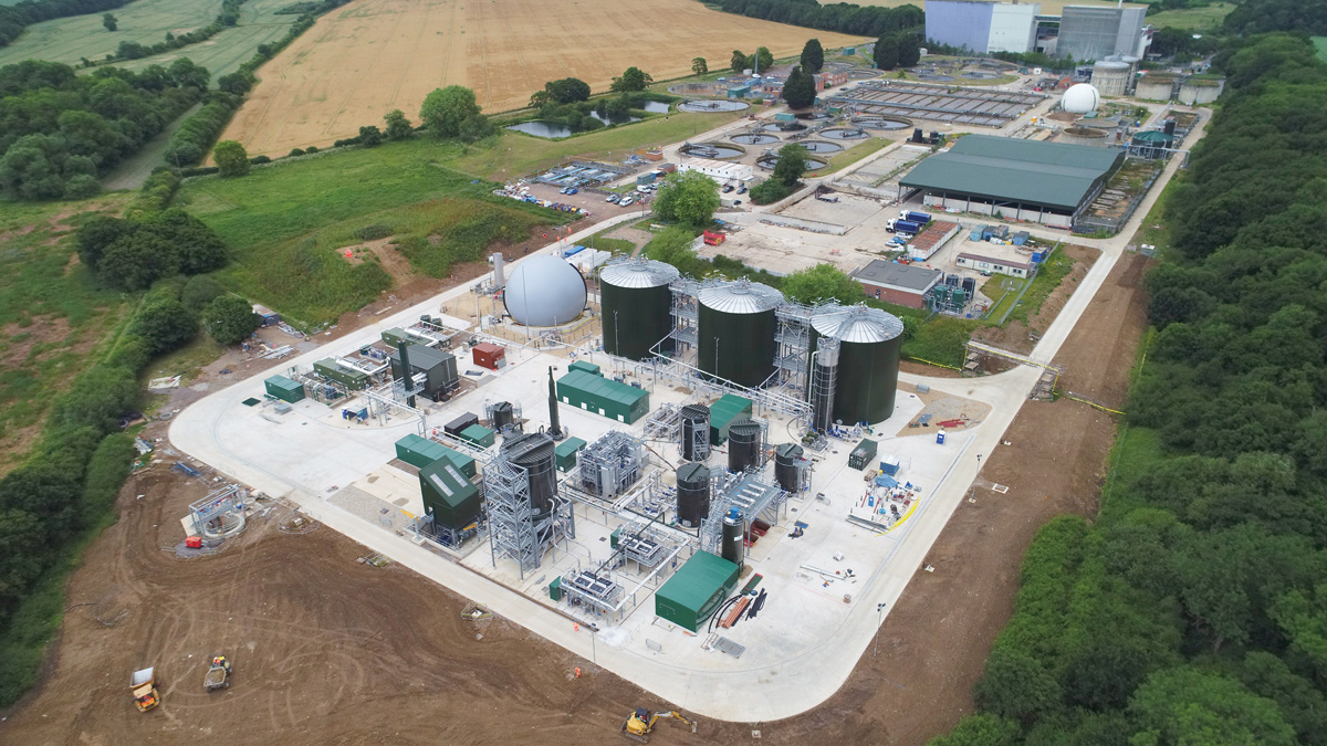
Basingstoke STC - Construction Progress June 2017 - Courtesy of eight2O Drone Service
The Basingstoke Sludge Treatment Centre (STC) incorporates liquid and caked, raw sludge import facilities together with thermal hydrolysis and anaerobic digestion plant which will process 53tDS/day of sludge from Basingstoke, Farnham, Fleet, Guilford and Newbury. This will fulfil Thames Water’s strategy to cease unsustainable liming activities at the four satellite sites up to the 2036 design horizon. Combined heat and power (CHP) engines, installed as part of the project will generate sufficient green electricity to satisfy the STC and the existing STW requirements and surplus power will be exported to the Grid.
Undertakings
The sludge treatment centre is being constructed and commissioned by the eight2O alliance which is the largest alliance in the water sector. The partners involved are Thames Water and two design and build joint ventures made up of Costain, Atkins, Black & Veatch (CABV) and Skanska, MWH (now Stantec UK) and Balfour Beatty (SMB). MWH also leads programme control and IBM is the technology innovation partner.
At Basingstoke STC, MWH UK began the detailed design in March 2015. Costain started construction in September with targets of achieving ROCs accreditation on the new CHP engines before the scheme closed in March 2017 and will achieve full operational benefits by March 2018.
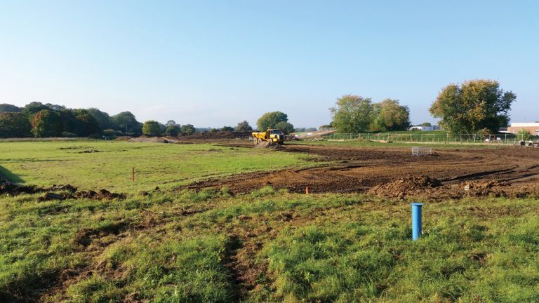
Stormwater treatment plot before construction – Courtesy of Costain
Design options
At an early stage in the project both the thermal hydrolysis process (THP) and a new variant, the intermediate thermal hydrolysis process (iTHP), were considered. The latter has been shown to produce more biogas than THP which in turn results in more power generation. However for sites with a high proportion of imported cake, such as Basingstoke, the cost of diluting the cake prior to primary digestion and then dewatering the primary digestate prior to thermal hydrolysis exceeds the revenue generated from exporting electricity from the site, so iTHP was not economically viable in this installation.
The PR14 business plan solution was based on expanding the existing sludge treatment facility within a very small site area which would have caused operational, demolition and construction phasing difficulties. In view of this MWH recommended that the STC be built off–line on some of the old stormwater treatment plots immediately to the east of the existing STW.
This provided numerous benefits in terms of minimising interfaces with the existing operational works during construction and the optimisation of plant and services’ layout was not compromised by lack of space.
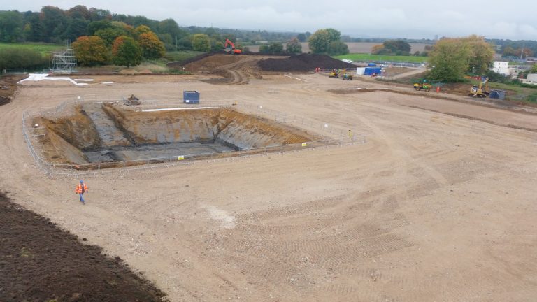
Excavation for cake import bunker – Courtesy of Costain
Existing plant
The existing sludge treatment plant at Basingstoke STW treats 12.9tDS/d and consists of gravity belt and picket fence thickeners, primary and secondary digesters, digested sludge dewatering belts and a covered cake storage area.
Electricity from 2 (No.) existing CHP engines is used on site. The existing digesters and CHPs will be decommissioned once the new STC is commissioned.
New plant
The STC is designed for a throughput of 53tDS/d; under normal operation however it can accommodate up to 70tDS/s in order to catch up with a backlog of sludge imports when the THP and steam boiler are shut down for annual servicing and during infrequent unplanned shut downs.
At the normal throughput of 53tDS/d, the CHPs will generate 2.23MW and satisfy the 1.32MW total demand of the STC and the existing STW and the remainder will be exported to the Grid.
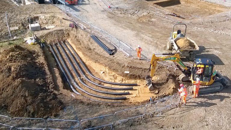
Over 3500m of underground pipework has been installed – Courtesy of Costain
The STC comprises the following:
- Imported sludge cake facility.
- Imported liquid sludge facility.
- Indigenous sludge collection and transfer to STC.
- Liquid sludge blending, buffering and screening.
- Pre-THP dewatering, polyelectrolyte storage, preparation and dosing for pre-THP dewatering.
- Sludge cake back-mixing and dilution.
- THP feed silo.
- Thermal hydrolysis plant.
- Sludge cooling and transfer to digesters.
- Digesters.
- Digested sludge collection and transfer.
- Digested sludge dewatering and storage (existing).
- Biogas storage and utilisation.
- Gas engines.
- Dual fuel boiler (biogas and diesel oil).
- Odour control plant.
- Liquor collection and return; partial flow to the existing aeration plant, the remainder to a liquor treatment facility.
- Final effluent supply.
- Potable water supply (reverse osmosis plant).
- Standby generator for essential services.
- Auxiliary fuel storage.
Building on previous experiences
Whilst THP technology has been used in the wastewater industry for some time now and the actual THP optimised, it is the design and operation of ancillary systems that determine the success of the plant. Indeed there are currently projects being undertaken across numerous water companies to ‘optimise’ the operation of existing installed THP plants.
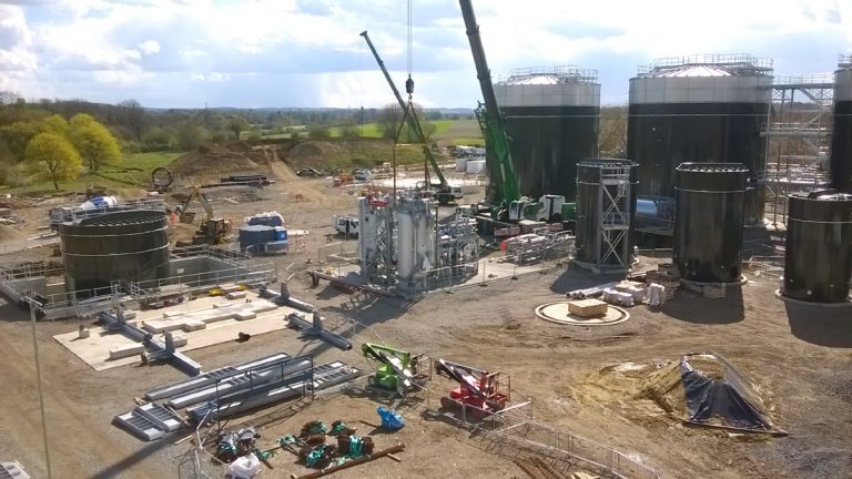
CAMBI THP being lifted into position – Courtesy of Costain
The project team worked closely to build on previous experiences and good knowledge of existing THP plants to make Basingstoke THP the best it can be, some points of particular note:
Digested sludge collection tower: A digested sludge collection tower has been constructed to counter issues and problems associated with digester surging (volume changes). THP sludge is very digestible, producing a lot of gas compared to non-THP digestion. As soon as THP sludge is fed into the digester, within minutes biogas is produced. Thus, the digester feed rate has a significant effect on the operation of the digesters; an increase in feed rate results in an increase in gas entrainment, resulting in a density fall and rapid volume increase. This effect causing a ‘surge’ and sudden discharge from the digester.
As the digesters work on hydrostatic displacement there may be a surge out of 3 main tanks, the digested sludge collection tower acts as a balance tank which reduces the risk of rapid volume loss and allows sludge levels to be managed by the forwarding pumps.
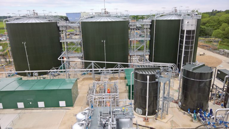
Kirk GFS tanks installed. Digested sludge collection tower on right in front of digester – Courtesy of Costain
Foaming in digesters: This has been an issue on many of the earlier sites; which is due to what the ‘digestive’ bacteria excrete (a washing up liquid like substance) that creates a stable layer on top of the sludge. In theory, if there is a continuous feed, with a continuous discharge then all should be well.
However, small variations in gas production happen as soon as sludge stops overflowing/discharging from a digester; this results in degassing in the digester and a thicker (higher density) of sludge in the discharge pipe which cannot readily be pushed through. Pressure keeps building up until the ‘slug’ of higher density sludge can be pushed through.
On the outlet pipes of the digesters at Basingstoke, an air lift system has been installed to encourage the density in the riser pipe to remain relatively low by introducing air into the system.
Ammonia consent: Basingstoke STW has a 1mg/l ammonia consent. As part of the project, Basingstoke will import three times its indigenous sludge production thus generating more ammonia load which will put strain on the STW to maintain consent. To overcome this issue a Demon LTP is being installed for ammonia removal; a low energy and low sludge production solution.
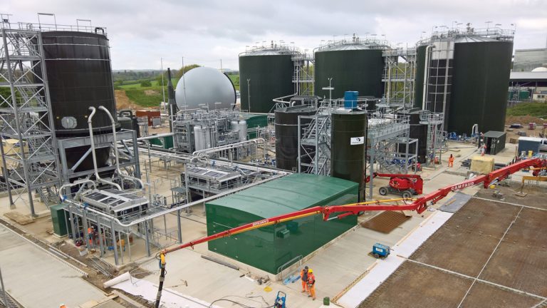
Road construction underway. Dewatering belts and polymer dosing kiosk in the foreground – Courtesy of Costain
Natural fuel availability: There is no natural support fuel to rely on as providing a new gas supply to site was considered too expensive so the THP will in effect run-itself, using biogas to run the plant. A small diesel storage has been provided to enable ‘start-up’ during the commissioning phase and following maintenance periods.
Use of low grade heat from CHP engines: To heat final effluent for dilution of sludge pre-THP and also heating the hot well. Both reduce steam consumption which means more biogas available for generating electricity.
Back-mixing facility: THP needs to be fed at a relatively consistent feed dry solids to achieve optimal performance. Incoming cake is too thick to feed directly. The use of screened liquid sludge to dilute pre-dewatered sludge down to 20% dry solids before going to the THP feed silo has been provided. This saves on polymer usage in the pre-dewatering process.
Use of low grade heat: to keep LTP bacteria warm.
Construction
To realise the potential fast delivery benefit of a design and construct approach, civil designs were called for in advance of receiving ‘official’ supplier design information, thus the handling of interfaces with key plant suppliers was crucial to the success of the project. At the time of writing (August 2017) circa 8000m of underground pipework, 6000m of above-ground pipework and 5000m of cabling has been installed.
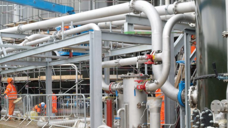
End of one of the pipe corridors filling up quickly – Courtesy of Costain
In the absence of supplier information, experience based design decisions were important in facilitating the installation of such services, in particular designating two main above ground service corridors and locating plant/setting the site falls to facilitate the gravity pipe runs.
Underground structures were minimised to reduce potential for delays due to potential groundwater and increased construction costs associated with excavations. There were only two pumping station shafts (each approximately 7m deep) and one large cake import bunker (20 x 15 x 5m deep) that required substantial excavation.
Importantly, much of the mechanical plant (e.g. FE transfer pumping station), was skid mounted to reduce installation time on site and some of the larger plant items, including the THP plant, were assembled off-site prior to being dismantled and reassembled on site to minimise installation issues.
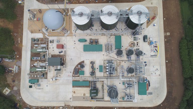
Basingstoke STC – Drone aerial view – Courtesy of eight2O Drone Service
Supply chain
Over 40 suppliers were engaged, mainly under NEC Option C Target Cost, from local contractors to as far afield as the Netherlands. The largest value contracts were FSD (pipeline supply and design) £4m and CAMBI (THP plant) circa £3m.
The longest lead in time from inception to delivery was approximately 10 months, and nearly 160 CEs have been raised and closed to date. Spending peaked between November 2016 and March 2017 at circa £1.3m per month.
- Pressurised Sludge Screens: Huber Technology
- Polymer Dosing: Richard Alan Engineering
- Dewatering Belts: Kent Stainless Ltd
- Imported Cake reception facility: CTM Systems Ltd
- GFS Tanks: Kirk Environmental Ltd
- THP: Cambi AS
- Engines: Edina Group
- Boiler: Dunphy Combustion Ltd
- Sludge thickening progressive cavity pumps (Basingstoke): SEEPEX UK Ltd
- Pumps: Xylem Water Solutions
- Pipework: FSD Ltd
- Liquor Treatment Plant: SWECO
- Odour Control: Plasticon UK Ltd
- Tank Mixing: System Mix and Utile
- Waste Gas Burner: Flare Products Ltd
- Transformers: SSE
- Heat Exchanger: HRS Heat Exchangers Ltd
- Commissioning, operation, training, optimisation, maintenance: PBJ Engineering Services Ltd
Progress
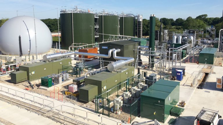
2 (No.) CHP engines in foreground. Engine start-up achieved to programme using temporary gas supply – Courtesy of Costain
The programme was driven by the need to achieve ROCs accreditation of the engines by March 2017. Ideally this meant that all plant would be up and running; the site would be receiving and processing sludge imports, the THP would be in operation and digesters producing the gas required to run the engines.
To ‘de-risk’ the programme MWH suggested and designed a temporary gas main which was installed across the site from the existing gas holder to allow engine start up in advance of March 2017. Currently the CHP engines are running, the digesters have been seeded and one is being brought up to temperature.
First imports are expected in June, ramping up to a fully commissioned works by March 2018.


