
Bamford WTW (2026)
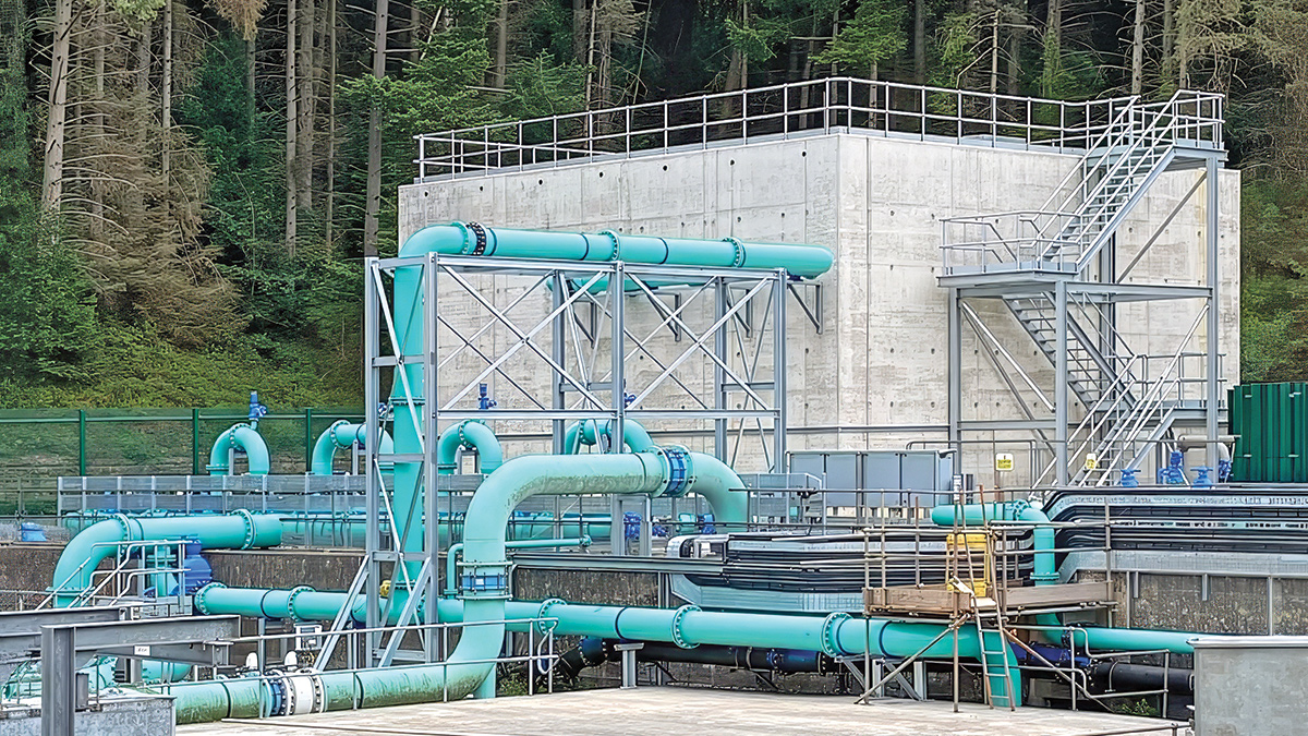
The new clean backwash tank – Courtesy of MWH Treatment
Located in the Peak District National Park, Bamford Water Treatment Works (WTW) is Severn Trent’s third largest. It receives raw water from Ladybower, Derwent and Howden Reservoirs, to supply potable water to Derby, Nottingham and Leicester. The works is situated within the Upper Derwent Valley, an area characterised by upland moorland and gritstone escarpments, including Bamford Edge and Derwent Edge to the north and Win Hill to the west. The River Derwent traverses the valley. The Derwent and Howden Reservoirs were constructed in the early 20th century, and downstream of the Derwent Dam, the 504-acre Ladybower Reservoir was completed in 1945. The village of Derwent was “drowned” to make way for Ladybower Reservoir, and in drought years, when the level of Ladybower falls, the ruins of the village can be seen from the banks.
Background & the need for change
Raw water from the Ladybower, Derwent and Howden Reservoirs is blended and treated at Bamford WTW before entering the Derwent Valley Aqueducts (DVA) network. As the supply network is gravity-fed, Bamford WTW provides one of the lowest-cost sources of treated water within Severn Trent’s supply area.
Severn Trent commissioned a resilience enhancement programme to strengthen process integrity and maximise the water output from Bamford.
The scheme included designing and implementing a new fail-safe control system, a run-to-waste facility, and reconfiguring the treatment process into two independent treatment streams. The project also addressed critical single points of failure, significantly improving operational resilience, compliance assurance, and security of supply.
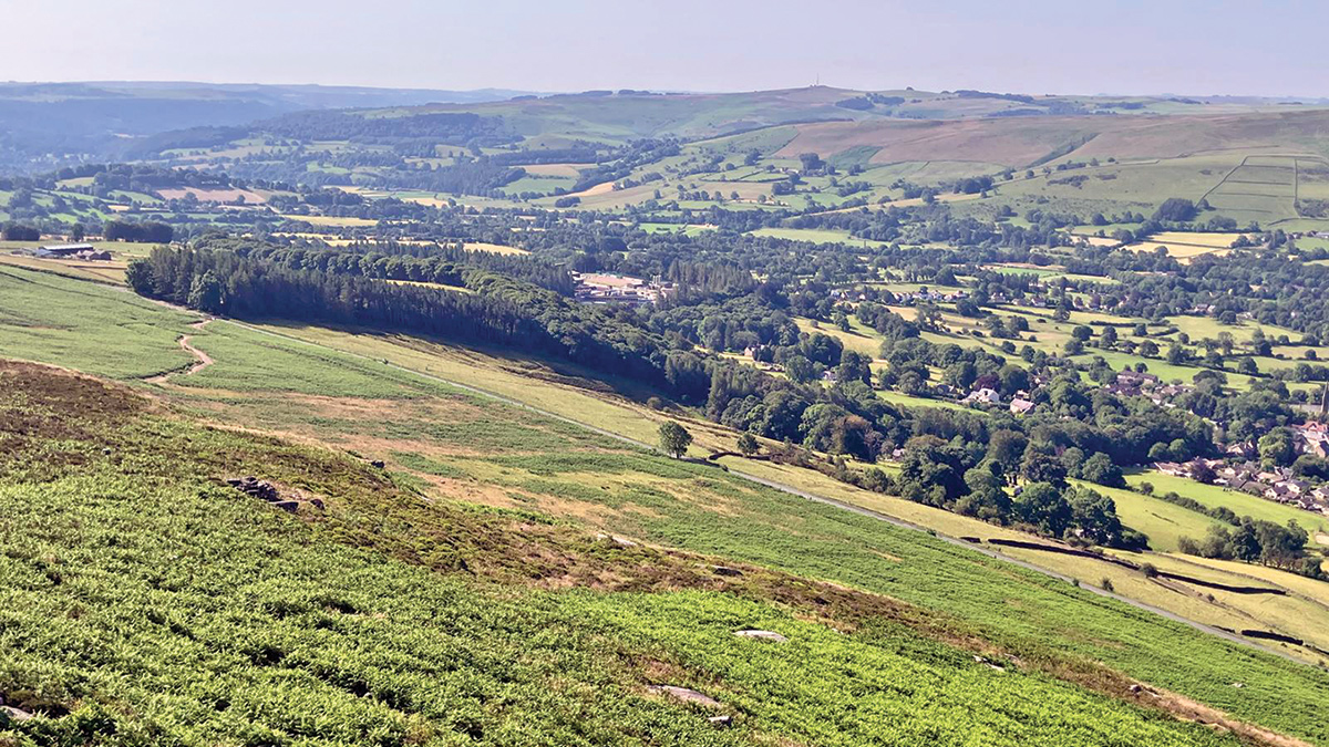
Bamford WTW is surrounded by dramatic upland landscapes in the Peak District National Park – Courtesy of MWH Treatment
Engineering a solution through collaborative thinking
Delivering a scheme capable of dividing Bamford WTW into two fully independent treatment streams, both hydraulically and electrically, presented a significant engineering challenge. Originally commissioned in the early 1900s, the site comprises a combination of legacy infrastructure and subsequent upgrades, with several original assets remaining in operational service.
The project was further constrained by the requirement to maintain continuous operation throughout construction. Located at the head of the DVA, Bamford WTW cannot be taken offline without impacting water supplies to approximately 60,000 properties.
The resilience programme involved the design, installation and commissioning of modifications capable of accommodating flows of up to 202 MLD while maintaining regulatory compliance and security of supply. Successful delivery required close collaboration between MWH Treatment’s design, construction and commissioning teams, together with Severn Trent’s project management, service delivery, public health and water quality specialists.
To manage the scheme’s complexity and minimise operational risk, the project was structured around a number of key delivery areas.
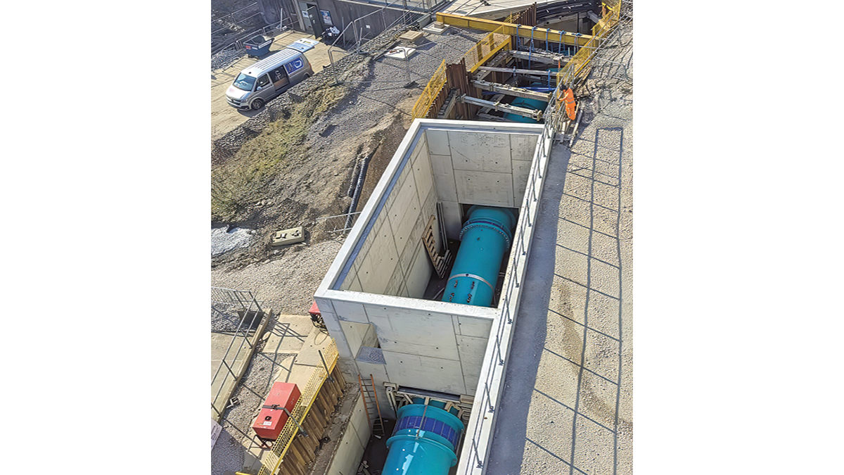
The new contact tank inlet chamber and pipework – Courtesy of MWH Treatment
Bamford WTW: Supply chain – key participants
- Principal designer & contractor: MWH Treatment
- Civil design: Eastwood Consulting Engineers
- Asbestos removal: RSK Asbestos
- Concrete shafts: Westshield
- Civils contractor: M2 Civils Ltd
- Civils contractor: Hollywood Civil Engineering
- Hot tapping: UTS Engineering Ltd
- Sheet piling designer & contractor: Ivor King The Piling People
- Shoring: National Trench Safety UK
- FRC specialist: Smithform
- Electrical installation: Main Electrical Ltd
- Electrical installation: Southern & Redfern Industrial Solutions
- HV/LV infrastructure: Central Power Services
- Lifting equipment: T Allen Engineering Services Ltd
- Orthophosphoric dosing: Lintott Control Systems
- OSEC, hypo, bisulphite & Kalic dosing: IIES (Northern) Ltd
- Dosing hoses: FT Water Treatment
- Process water booster pumps: NPS Engineering Group
- Mechanical pipework: Powerrun Pipe-Mech Ltd
- Mechanical pipework: Fluid Sealing & Engineering (FSE)
- Mechanical pipework: Diamond Fabrications
- MCCs: BGEN Ltd
- Kiosks: Industrial GRP
- Kiosks: Quinshield Ltd
- Valves: Cotswold Valves Ltd
- Access metalwork: Dixon Engineering Ltd
- Access metalwork: GT Fabrications
- Site buildings: Midbrook
- HVAC system: Air Technology Systems
- Fire & security: TP Fire & Security Ltd
- Security fencing: Binns Fencing Ltd
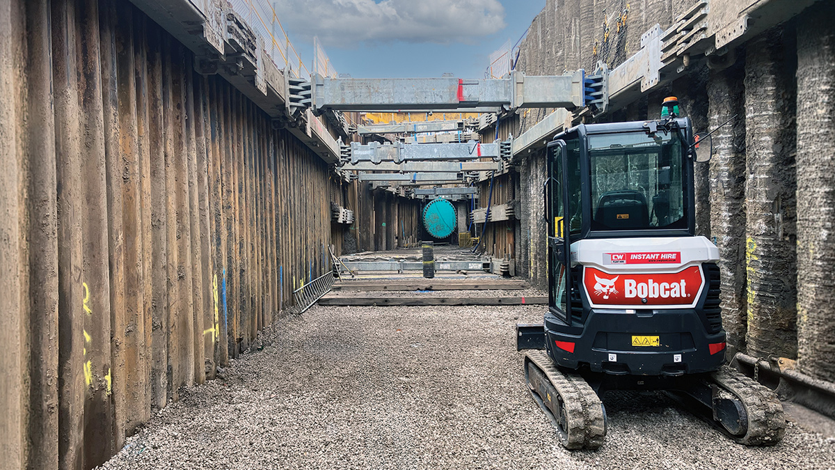
Continuous flight auger pile wall together with sheet pile temporary works – Courtesy of MWH Treatment
An automatic fail-safe system
To prevent water from a single stream that is exceeding water quality targets from entering the supply, an automatic fail-safe system was required.
This involved reconfiguring the existing water quality and control systems used for a combined twin-cell contact tank and dedicating it to one cell of the twin-cell tank. New water quality and control systems would be provided for the other contact cell together with a new inlet main (delivered as part of the hydraulic dual streaming). The new and modified control systems would isolate the contact tank outlet, DAF process and RGFs in the event of out of specification water being detected.
Run to waste system
In the event of a water quality failure, a run to waste system was required that would return flows back to the head of the works at a rate of 35 MLD via intermediate storage and de-chlorination.
This involved the provision of a new Emergency Return Pumping Station (ERPS) to be constructed adjacent to the existing contact tank structure. The pumping station was constructed by underpinning techniques to a depth of 11m
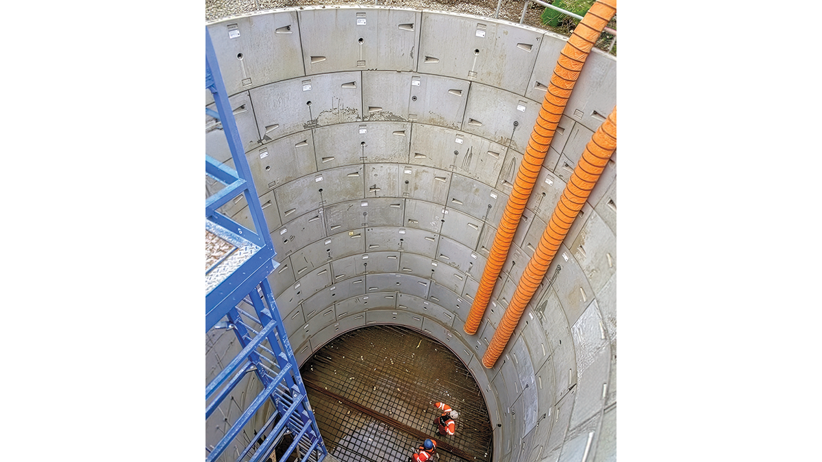
The new emergency return pumping station wet well – Courtesy of MWH Treatment
To supply the new ERPS, two new connections into the existing contact tank cells upstream of the existing outlet penstocks were made. These connections were auger bored from the new shaft into the contact tanks to the existing contact tank valve chamber.
Two new duty/standby submersible pumps were installed to deliver the 35 MLD flow rate together with a new below and above ground 600mm rising main. The new rising main discharges in the redundant clarifiers. The clarifier structure has a total of eight cells available; each cell holds a volume of 1 ML.
The existing re-purposed clarifiers were modified with several cross-connection valves/pipes and provided with a new common duty/assist/standby return pumping station, to return flows at a maximum flow rate of 10 MLD to the head of the works. The new rising main to the head of the works also included the provision for sodium bisulphite dosing for de-chlorination.
Process dual streaming of the works
The existing inlet and DAF were substantially dual steamed following the commissioning of a previous scheme completed in 2012. However, some minor control and valve modifications were needed on the new inlet and the existing DAF outlet.
The existing rapid gravity filters were far more complex to dual-stream. There are 24 filters on site operating in three banks: RGFs 1-16, 17-22 and 23-24. All three banks are at different levels across the site, and volumetrically, RGFs 23 & 24 (commissioned in 2016) are significantly larger than the other 22 filters.
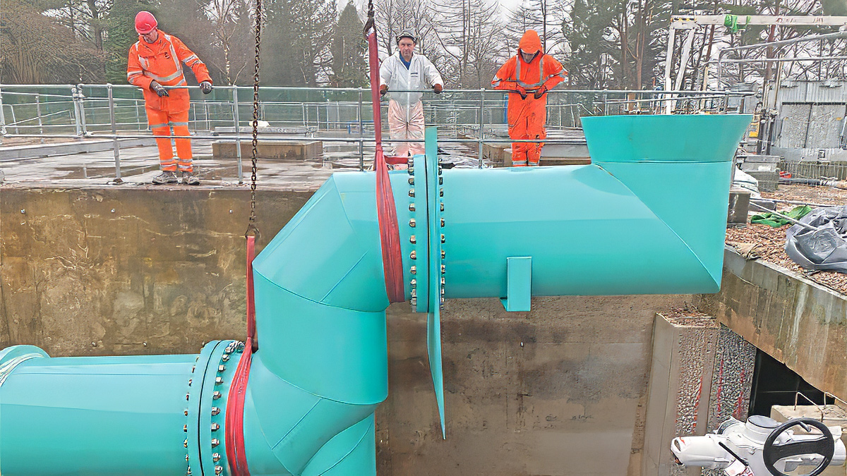
The new contact tank overflow lifted into position – Courtesy of MWH Treatment
RGFs 1-16 comprise of a dual inlet channel/gallery with flows entering the filters from either end of the building. To create two separate streams, a penstock was inserted within the channel towards one end, and RGFs 13-16 had the existing inlets modified to take flow from the same source that had been isolated by the installation of the penstock.
RGFs 9-12 had the outlets to the original common discharge main reinstated to combine flows with the discharge from RGFs 1-8. This allowed RGFs 1-12 to operate as one stream and RGFs 13-24 as the other stream. Two new stream specific control systems have been provided together with a new supervisory control system to manage filter washing across all 24 filters.
The RGF scope also included for a new twin cell clean backwash tank, with each cell filled from either stream, however the outlets are common to the four duty/assist/assist/standby backwash pumps that backwash all 24 RGFs by a combination of gravity or pumped flow depending on the filter level and wash rate.
The discharge main from RGFs 17-24 also had to be modified to prevent flows from bypassing the contact tank and discharging straight into the DVA. These modifications present a challenge, as the 900mm pipe requiring diversion was buried at the base of a steep slope supporting a site access road that had to remain in operation.
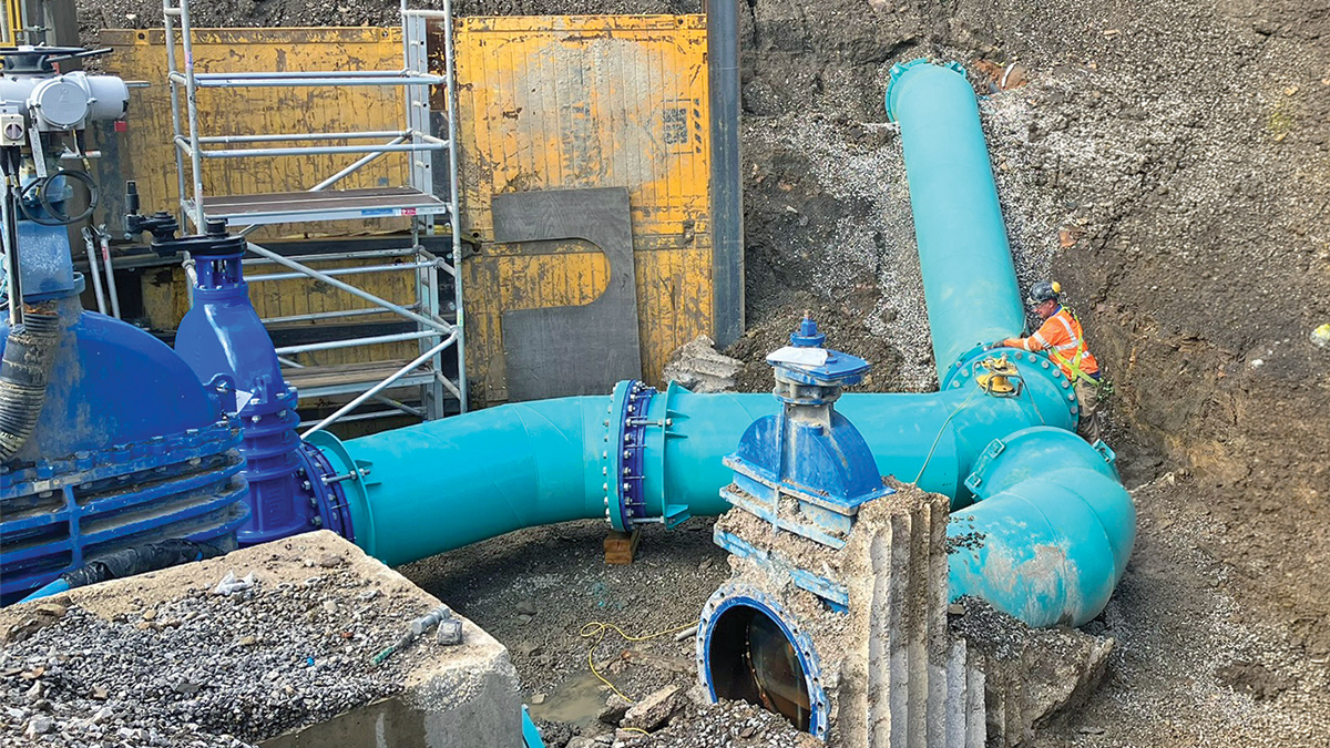
Pipework diversion for RGFs 17-24 – Courtesy of MWH Treatment
Given that the pipework installed around 2012 was backfilled with an extensive quantity of limestone fill, it made the temporary works complex and the excavation extensive in a small and difficult to access area.
The last and most challenging element of the hydraulic modification work was to create a new 1800mm inlet main to one cell of the existing contact tank. The existing orthophosphoric acid dosing system had to be removed to facilitate construction; therefore, a new dosing system had to be installed and commissioned prior to excavation works commencing.
Further complications arose around the existing operational lime plant that was adjacent to the excavation and local area ground levels. The location of the new pipe was within an existing slope with up to 3m variance along the length of the new 65m long pipeline. Two new structures were also required along the length of the new pipe for flow measurement and chemical dosing purposes.
To make a connection to the existing in-service main feeding the in-service contact tank from filters 1-16, a 1200mm hot tap was cored into the existing epoxy-coated steel pipe.
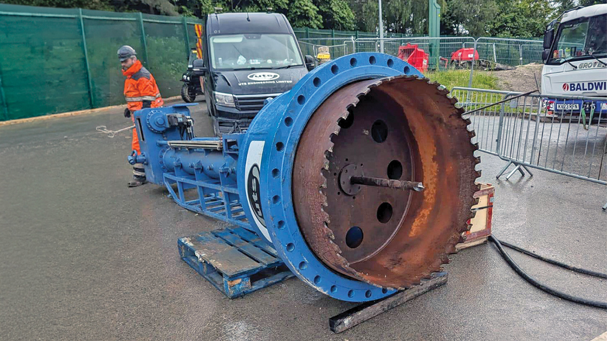
The 1200mm hot tap drill – Courtesy of MWH Treatment
At the contact tank end, the original solution was to lay a new 1800mm main below the existing 1200mm overflow pipe and create a new inlet in the side wall of the tank. However, the excavation depths would have undermined the contact tank, and given the proximity to the lime plant and operational services at the dig location, it was difficult to provide a temporary works design to facilitate the required excavation.
Therefore, a revised solution required the 1200mm overflow bell-mouth pipe inside the contact tank to be repurposed as a new inlet. To do this, the 1.5T pipe had to be removed from the wall coupling, rotated through 100° before refitting.
A new isolation valve was fitted to the outside of the tank and a new chamber constructed to house the new valve and the contact tank control and water quality monitoring equipment. A new wall penetration had to be cut into the wall of the contact tank, and a new overflow pipe fabricated and installed that reconnected to the existing overflow discharge main within the new chamber.
Once the new inlet chamber was complete, the temporary works could focus on the two new chambers and inlet main. This was done as a mixture of contiguous flight auger (CFA) piles and driven sheet piles to create one continuous wall.
The CFA part of the wall would also act as a back shutter for the two chambers that are linked together with a common base and back wall. The remaining temporary works on either side of the new chambers to the connection points were provided by sheet piles and frames.
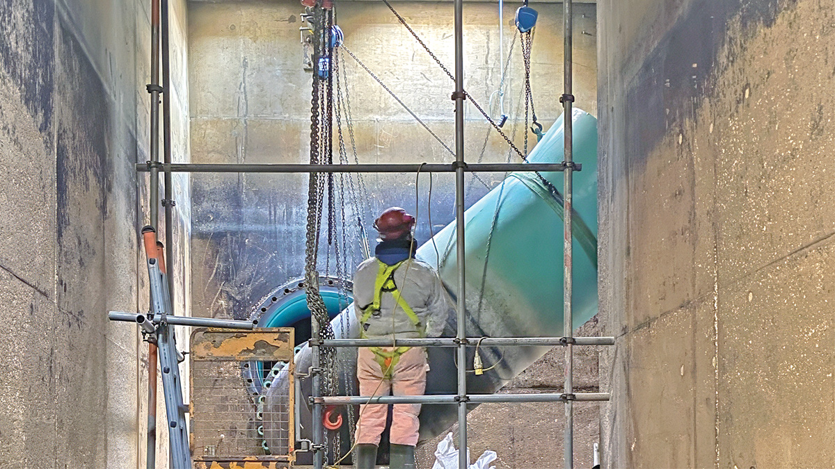
The existing overflow being lowered to create the new contact tank inlet – Courtesy of MWH Treatment
Power & control to be streamed together
Bamford has two external power supplies; one permanent and the second being an alternative switched supply that requires Distribution Network Operator (DNO) attendance to enable energisation. The existing supply had been modified, and the existing transformer and distribution board MCB21 were replaced with stream-specific transformers and new distribution boards MCB21 A, B and C. MSB21C is the new 1.5MVA generator interface panel that provides power to the whole site in the event of a mains failure. Uninterruptible power supplies (UPS) were provided to the process streams where the existing UPS became dedicated to a single stream.
From the new main circuit breaker (MCB), power distribution was provided such that either process stream could be supplied from either MCB, or one MCB could provide power to both streams. All common assets such as lime or ferric would be fed from both streams and be provided with auto-changeover switches and a UPS to ensure bumpless changeovers in the event of power failure.
A new motor control centre (MCC) was provided at the works inlet to control flow to either of the two streams. Under normal use, the flow to either process stream would be split equally from the desired works output. However, should a works shutdown be initiated from a water quality failure, the system would increase throughput on the healthy stream to the maximum flow of 101 MLD, and decrease flow on the affected stream to 35 MLD.
Conclusion & summary
There were several significant challenges at Bamford WTW, including ground and topographical conditions, which necessitated significant temporary works to ensure safe working within deep excavations.
The sensitive location influenced how work at Bamford was delivered, given that Saltergate Lane must be used to access the site. Saltergate Lane is a typical, narrow Peak District lane with houses on one side and golf course the other. Bordering the golf course are native hedgerows and significant oak trees. The maximum width of the lane is 3.2m and it is a dog-legged on a steep incline at the halfway point. Whilst some of the Design for Manufacture and Assembly (DfMA) chemical dosing solutions could be broken down into smaller component parts, bringing the 1.5KVA generator and 220 tonne crane proved difficult.
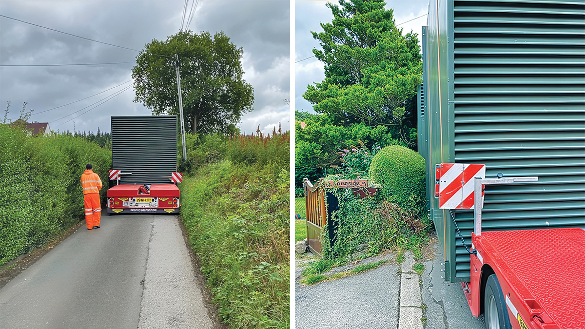
The new generator being delivered to site along narrow lanes – Courtesy of MWH Treatment
Given the age of the works at Bamford, its hillside location and the undertaking of multiple improvement projects, there is little space left for further development of the site and the addition of new and extensive services. Providing all new cabling, not only to the new dual-streamed works, together with its additional associated electrical resilience and new chemical dosing equipment, has required a significant number of new ducts (25km in length).
Providing these new services, while maintaining the existing services and process assets required, took longer than envisaged, as hand-dig or vacuum excavation methods were selected.
The integration of a new dual-streaming and fail-safe control system was difficult to achieve, with some parts of the works having to be removed from several assets and integrated into new or other existing assets. The new control system required various levels of change or modification to every existing control system on site.
The Bamford WTW Resilience Upgrade was delivered on a live operational site, requiring extensive modifications to process infrastructure and control systems without interrupting water supply. The extent of the investigative and design work required to fully understand the complex existing system to allow the integration of a new works supervisory system proved to be far more extensive than was ever envisaged or understood at concept.
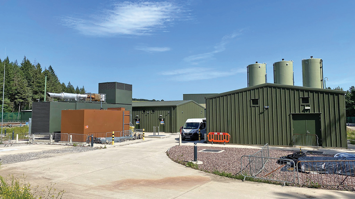
The new generator and bulk fuel storage tank - Courtesy of MWH Treatment