Tideway Central – Albert Embankment Foreshore (2021)
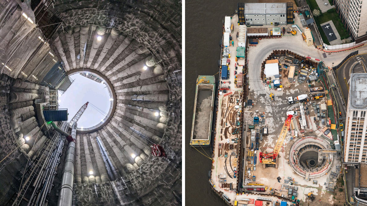
(left) ALBEF shaft and (right) ALBEF Cofferdam 1 - Courtesy of FLO JV
The Thames Tideway Tunnel project will upgrade London’s Victorian sewer system, which was developed by Sir Joseph Bazalgette in the mid-1800s for a population of 4 million people. Now with over 8 million Londoners, the system capacity, around 6mm per hour rainfall in the catchment, has been exceeded and the discharges of mixed water through different combined sewer overflows (CSOs) into river Thames are frequent. Currently under construction, the new 25 mile-long main tunnel running at an average of 40m below the riverbed, will intercept the discharges of the existing sewer outfalls at the riverbanks through the permanent structures. The collected wastewater will be conveyed to the Beckton STW for treatment and then returned to the Thames Estuary.
Central Section
A Ferrovial Construction/Laing O’Rourke Joint Venture (FLO JV) was appointed as principal contractor for the Central Section between Fulham and Bermondsey. Eight CSOs spread along the river will be connected through culverts to a new interception chamber and then to a shaft structure. From the shaft, the flows will be conveyed into the main tunnel which was excavated with two 8.8m diameter TBMs. The permanent structures (culverts, interception chambers and shafts) are being constructed in new land reclaimed to the river by temporary cofferdams that enable the construction in the dry. These cofferdams are U-shaped structures tying-in against the existing river wall and come in two types: double skin and single skin. This paper outlines the design and construction methodologies at the Albert Embankment Foreshore site.
Albert Embankment Foreshore (ALBEF)
The ALBEF site’s purpose is to intercept the Brixton and Clapham CSOs which are located downstream and upstream of Albert bridge, respectively. The south bank of the River Thames at this location is full of existing assets that increase the complexity of the design and construction of the works. The Victoria Line is located 10m downstream from the Clapham CSO. The MI6 and Camelford house (a sixteen-storey building) are located in front of the site and upstream there is an archeological area protected by Museum of London Archaeology (MOLA). Furthermore, in the riverbed underneath of the bridge deck the old bridge pier foundations had to be taken into account in the design stage.
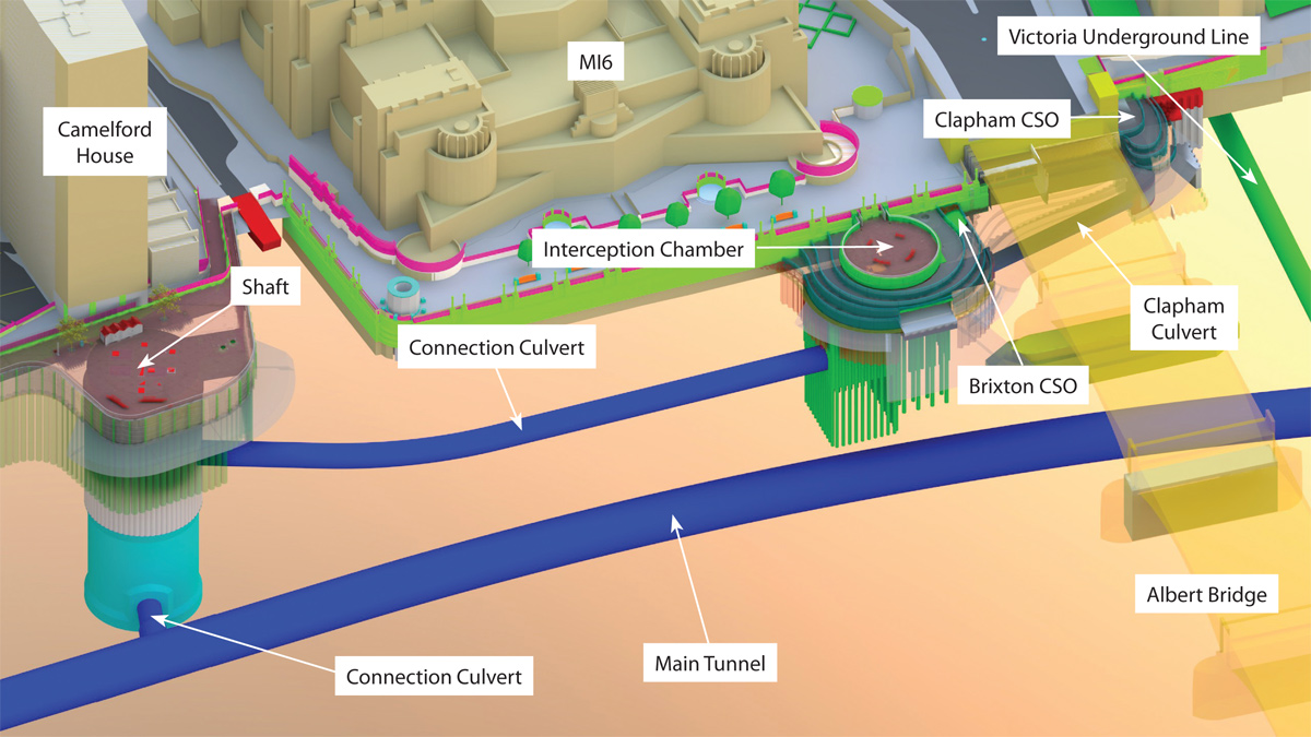
Permanent works at ALBEF site – Courtesy of FLO JV
ALBEF’s permanent works system has the capacity to convey discharges of up to 22m3/sec. The system will collect and divert the Clapham CSO discharges into the interception chamber through an underground culvert that runs underneath Vauxhall Bridge. The Brixton CSO discharges will also be diverted into the aforementioned interception chamber and, from there the flows will be conveyed to the main shaft located 100m downstream through a connection culvert. Finally, the flows are discharged into the main tunnel which ends at the Beckton STW. All the permanent works structures have a design life of 120 years.
The permanent shaft
The permanent shaft (16m in diameter and 50m deep) was excavated in the dry inside the reclaimed area of a twin wall temporary cofferdam, called Cofferdam 1. In this reclaimed area of 3,415m2 and 6m below high tide, a piling rig installed the secant piles at 26m deep. There are two types of secant piles that are alternated in the shaft perimeter, reinforced concrete piles called males, and mass concrete piles called females, both types being 1.3m in diameter. Once the shaft was excavated to the tip of the secant piles, the excavation continued using a sprayed concrete lining. This was excavated in 1m advances until formation level of the base slab was reached.
The 3m deep base slab was cast in one continuous pour over a 15-hour period which required 850m3 of concrete supplied from three separate batching plants.
The connection culvert tunnel (3.2m internal diameter (ID) and 110m in length) and connection tunnel (3m ID and 12m in length) were both formed through a combination of sprayed concrete primary lining and a cast in situ secondary lining.
To facilitate construction of the permanent structures below ground, a robust dewatering system was in place targeting both the intermediate and lower aquifer. The connection tunnel drive was particularly challenging owing to difficult ground conditions. To overcome this a temporary pipe arch was installed to ensure the tunnel could be formed safely.
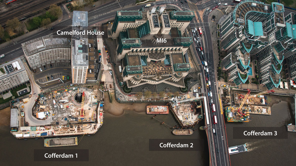
ALBEF plan view – Courtesy of FLO JV
As commented before, the shaft development is located in front of the Camelford House office block, the foundations of which are approximately 5m away from the excavation. To establish the interaction between the building foundation and the shaft, a detailed FEM model was developed. The model certified that the excavation methodology was safe and did not impose any detrimental effect on the adjacent building.
The transportation of spoil was carried out by barge to minimise the impact on the urban traffic. Cofferdam 1 is equipped with a mooring arrangement where barges up to 1,000 tonnes in weight are able to berth. The cofferdam walls consist of AZ36-700 embedded 5m into the London clay, and were built using jack up barges and flat top barges.
Albert Embankment Foreshore: Supply chain – key participants
- Project manager & designer: Tideway (Jacobs)
- Principal contractor & lead designer: FLO JV
- Main designer (permanent works): AECOM
- Sub-consultants (temporary works): Robert West Consulting
- Sub-consultants (temporary works): Beckett Rankine
- Sub-consultants (temporary works): OTB Engineering
- Sub-contractor: JGL
The interception chamber
The interception chamber (area 274m2 x 28m deep)is located downstream of Vauxhall Bridge, upstream of an archeological exclusion zone (where Mesolithic timbers are located), next to the Brixton CSO and in front of the MI6 building. The chamber was excavated using a secant pile perimeter within the reclaimed area of Cofferdam 2. It was built using a top down methodology. First the upper base slab or roof was built, then two levels of reinforced concrete perimeter beams were poured. Once the bottom of the excavation was reached, a 1m-thick reinforced concrete base slab was poured. Finally the secondary lining was cast between reinforced beams. This methodology avoided the use of temporary props and reduced the temporary works required.
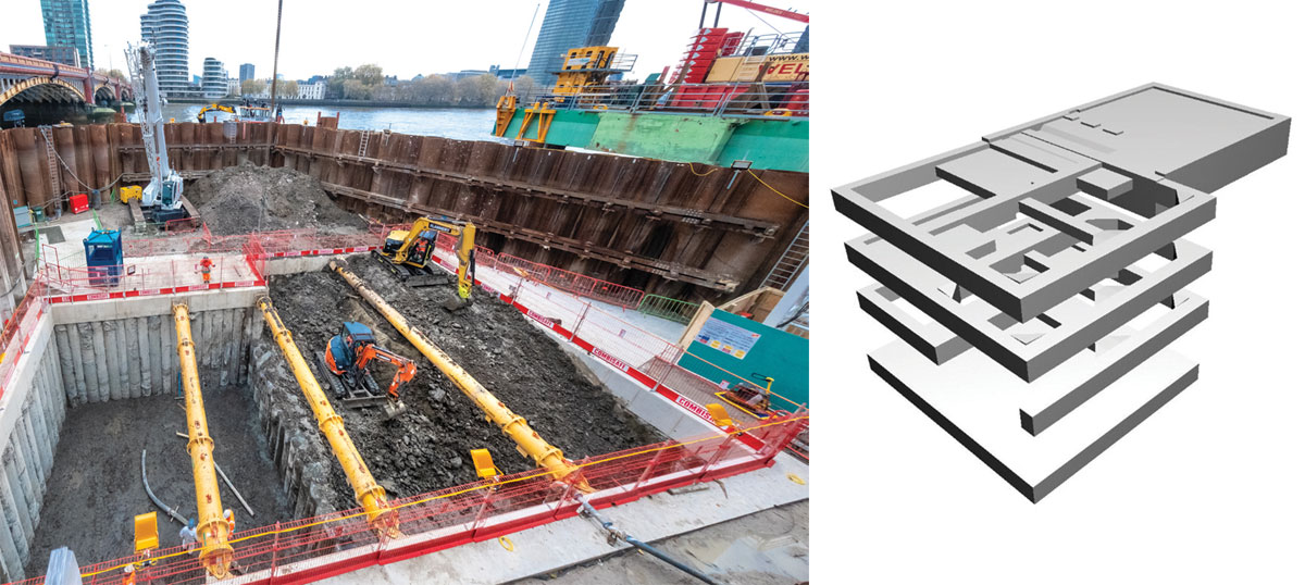
ALBEF Cofferdam 2 interception chamber – Courtesy of FLO JV
Cofferdam 2 enables the construction of the interception chamber and the Brixton’s new culvert in dry conditions. The structure is also designed to receive the pipe jacking operations of the new Clapham Culvert downstream. It is a combined structure of steel tubular piles and sheetpiles embedded 10m in the London clay. The reclaimed area is divided into three parts by internal sheet-piled walls, the central area where the interception chamber is excavated, the reception area for Clapham’s culvert and the Brixton CSO area.
The existing Clapham CSO is located upstream of Vauxhall Bridge and 10m away from the Victoria Underground line. In order to intercept the discharges and connect the existing opening to the system, a new permanent culvert is built. It consists of a reinforced concrete structure divided into three main zones and built in a dry environment within the reclaimed area of temporary Cofferdam 3, which is also divided into three main areas.
Cofferdam zones
Zone 1 starts at the Clapham CSO and runs 9.8m towards the north, perpendicular to the existing river wall. In this section, the cross-section of the culvert is reduced from the existing square of 3.5m sides to a 2.5m sides. Zone 2 is the transitional area where the culvert’s alignment turns 90 degrees and also, the section changes from a square to a circular cross-section. Furthermore, the height of the invert level of the culvert decreases 3m over 3.6m of length, creating a steep slope. To reduce the water energy and allow for a smooth transition, the culvert is equipped with concrete steps.
Zone 3 runs 32m parallel to the existing river wall, underneath Vauxhall Bridge at 5m deep ending in the interception chamber in Cofferdam 2. The culvert has a circular cross-section of 2.5m internal diameter with a 1:500 slope.
The temporary Cofferdam 3 enables the construction of the Clapham Culvert in the dry. It is a sheet-piled structure embedded 5m into the London clay and provided with internal frames that help resist the tide levels and allow a 7m excavation below the riverbed level.
At Zone 2 the cofferdam is a square area isolated from the riverbank called a launch chamber; the western wall is extended towards the south connecting with the existing river wall to enclose Zone 1. In order to not affect Victoria underground line and limit the vibration levels, the piles were driven using a Giken Supercrush silent piler, a non-percussive method.
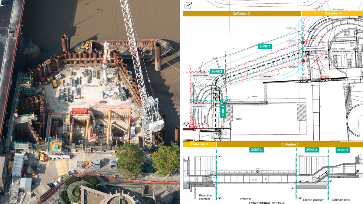
(left) ALBEF Cofferdam 2 and (right) permanent Clapham culvert and temporary works – Courtesy of FLO JV
The temporary works at Zone 3 consist of a short sheet piled channel called a twin wall that connects Cofferdam 2 with the launch chamber. The area within the sheet piles has been excavated into the London clay and filled with lean concrete. On top, there is a reinforced concrete slab that ensures the water tightness of the perimeter. Due to the tight headroom of 6.5m, the sheetpiles were driven using a Caterpillar 336FL 40Tonne excavator with a Movax vibratory hammer attached.
Zone 3 of the new Clapham culvert will be excavated through the twin wall using a pipe jacking method. The culvert will be composed of 14 jacking pipes with an internal diameter of 2.5m and 2.3m each in length with a steel collar embedded in the socket. In order to comply with the design life requirements, stainless steel has been introduced in the reinforcement of the segments. Furthermore, a 19.5mm closing width is required at the joints to ensure a design sealing pressure of 1.1 bar.
The segments will be jacked from the launch chamber towards Cofferdam 2 through the twin wall. The culvert will be excavated using a jack box tunneling system helped by an excavator at the front face. The jacking legs will be anchored to the launch chamber walls and will transmit up to 1750KN when pressing the tubular concrete segments through the lean concrete-London clay.
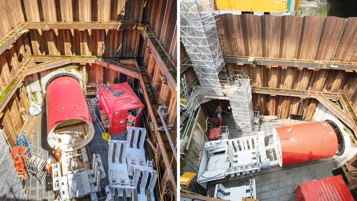
Launch chamber with pipe Jacking jacks – Courtesy of FLO JV
Conclusion
At the time of writing (July 2021), 60% of the ALBEF works are completed. The pipe jacking operations will start in August 2021. So many challenges have been overcome since 2016 to deliver a feasible solution that will enable the construction of London’s enhanced sewage system. The innovative design solutions to adapt the scheme to existing constraints such as consideration of impact on existing assets, demanding working conditions due to the significant number stakeholders or the challenging engineering input, are a good example of the value added by contractors with a strong technical background and design capabilities taking the role of main designers.


