Craighead WTW (2021)
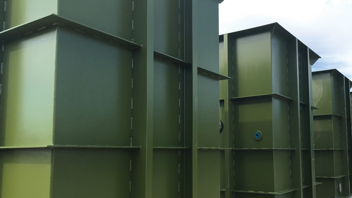
Construction progress - RGF tank installation - Courtesy of ESD
Craighead WTW is a new water treatment works located on a greenfield site close to the existing works in the north-east of Scotland. The project objective is to improve the treatment of water to the customers of the town of Huntley and surrounding areas. The existing Craighead WTW has reached the end of its economic life and is not suitable for refurbishment. To secure a long term supply of clean, safe and fresh tasting water, a new works will be delivered by ESD; a Binnies, MWH Treatment and Galliford Try Joint Venture formed in order to manage, design and deliver Scottish Water’s Q&SIV Non-Infrastructure Programme. The design of the project is being undertaken by Binnies.
Scope of works
The main components of the project are:
- Raw water intake pipelines.
- pH correction.
- Sludge thickening and storage.
- Final water mains.
- New 2 ML/d WTW incorporating:
- Coagulation | Polymer dosing | Flocculation | DAFs | RGFs | Contact tank| Phosphate dosing.
While much of the existing works will become redundant, some will be maintained including the existing CWTs, the network pumping station, Spring Wells PS and final sampling instruments.
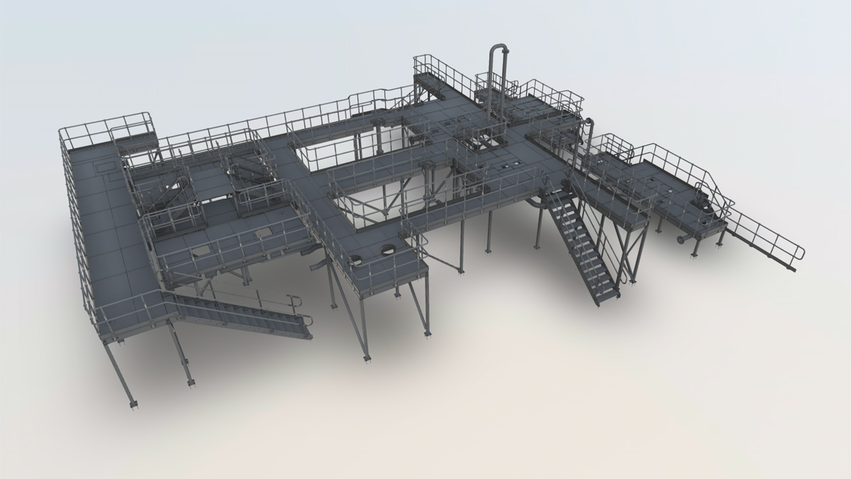
3D model of upper slab steelwork – Courtesy of ESD
Craighead WTW: Supply chain – key participants
- Main contractor: ESD JV
- Designer: ESD (Binnies)
- Building/mechanical/access steelwork & steel tanks: AJ Engineering & Construction Services Ltd
- Chemical dosing: Ross-shire Engineering
- Electrical installation: Interface Contracts Ltd
- WRc thickeners/sludge holding tanks: Homer Burgess
- Pumps: Xylem Water Solutions
- Pumps: NOV
- Blowers/compressors: Aerzen Machines
- Instruments: Process Plus
- MCC: MCS Control Systems
- Generator: DTGen
- Valves: Industrial Valves Ltd
- Pipelines: Fusion Pipeline Products
- Chain & flight scraper: Colloide Engineering
- Kiosks: Quinshield
A summary of the construction works at the new WTW being undertaken, including design and process considerations, as well as some of the challenges encountered for these main components, is given below.
Water treatment works
The new works will have capacity to produce up to 2 MLD of drinking water. Raw water will be sourced from Craighead Reservoir via a spring collection system, which is piped into the reservoir. These springs can be supplemented by water pumped from the River Deveron. Floc/DAF/RGF, the heart of the main treatment process, involves passing the raw water through a series of process systems which remove organic compounds, while allowing clean water molecules to pass through. Water that has passed through the process units will be further treated to ensure that it meets customers’ expectations at the tap.
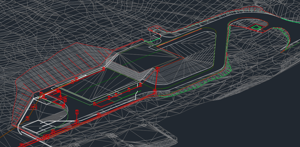
Civils 3D output showing site groundworks, road and drainage pipework – Courtesy of ESD
The WTW is positioned within a parcel of land on the opposite side of the main road from the existing site. The area included mature trees and on a sloped topography. The treatment works makes use of the existing land profile for the design and installation of a split level works incorporating a number of buried tank structures including the chlorine contact tanks below the upper ground slab. Utilising Civils 3D, the developed design allowed the minimisation of cut fill balances and also reduced the building footprint, planning impact and carbon impact.
The arrangement incorporated the main process units (floc/DAF/RGF) on the upper level, allowing flows to gravitate through the main treatment process. The main process unit tanks utilised DfMA principals and were all manufactured from steel off site and craned into position prior to main outer building construction. The principal of the design of the upper area utilised a ‘standardised’ design which Binnies had utilised in multiple sites historically. The previous development and reviews of the concepts and layout of the design allowed efficiencies to be made within the design, procurement and construction process by incorporating previous designs, manufacturing and construction methods.
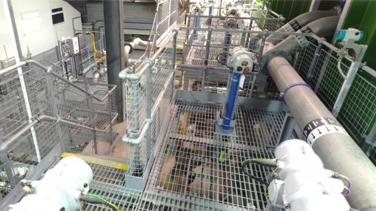
Example of laser scan output – Courtesy of ESD
While using Civils 3D to model the externals of the building the development of the building design and internals was also aided utilising digital engineering tools and concepts. The original design drawings used in the development of historical sites were all traditional 2D based and given the complexity of the pipework and accesses, were difficult to interpret. To assist with the understanding, 3D laser scanning of a similar site was carried out. This scan was then utilised by both design, construction and client teams to fully visualise layouts. The 3D laser scan was found to be extremely beneficial and enabled members of the team to carry out virtual ‘site visits’ and ‘walkthroughs’ whenever required.
The use of digital tools e.g. Civils 3D allowed the project designers to quickly and accurately visualise and understand the land topography. This knowledge in turn allowed the team to:
- Quickly adapt layouts to ensure most effective and efficient site placement.
- Make significant savings to the retainment structures and allowed removal of crib wall structures.
- Set site levels and profiles to minimise cut and fill volumes to limit the quantity of material removed from site.
- Assist with the planning application process and allowed third parties to quickly appreciate the layouts and visual impact of the works.
- Interface Civils 3D with Revit further enhance our design offering.
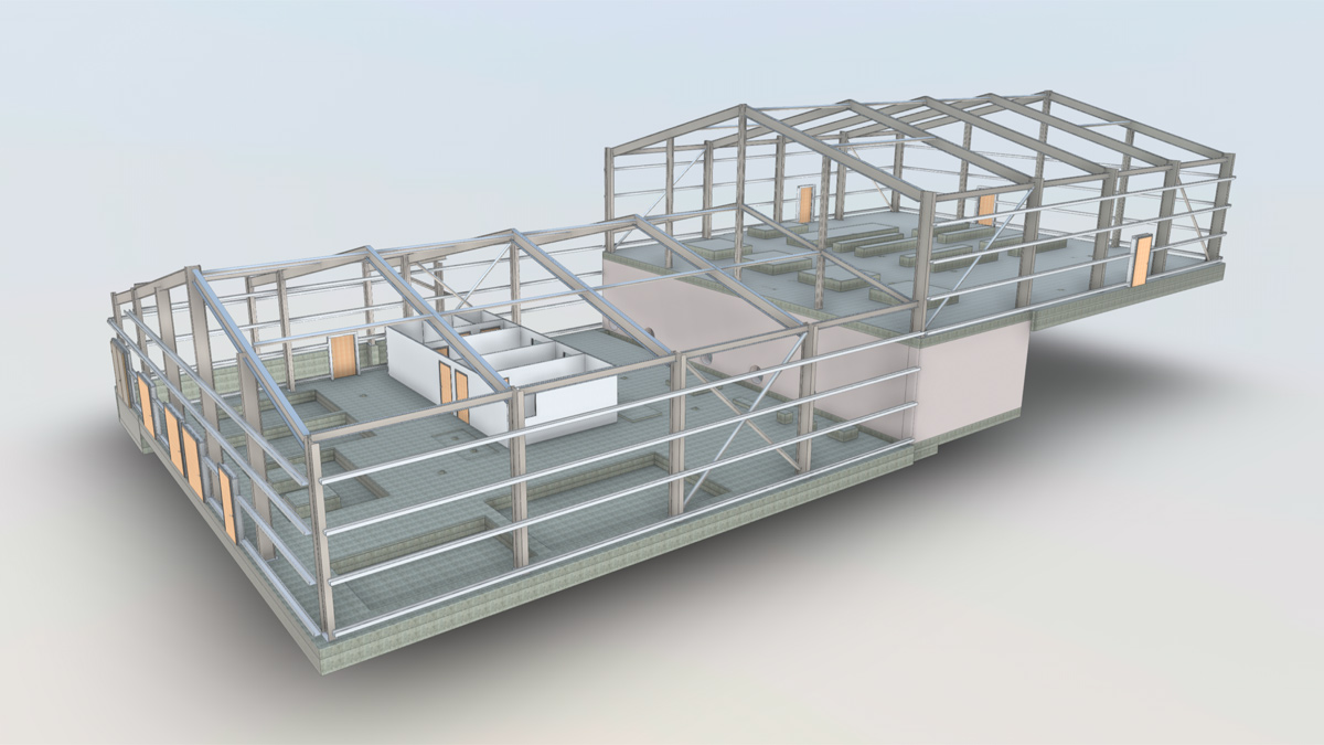
Model of treatment building – Courtesy of ESD
The lower floor level of the building incorporated a pump gallery, MCC room, accommodation block and the chemical dose systems, used as part of the treatment process. The layout within this area was more bespoke due to specific plant chemistry, developments within chemical dosing arrangements and specific client specification requirements. However, what was developed has now been adopted as a standardised design which has been, and will be, utilised on other similar plants.
As well as the main process tanks, DfMA was also utilised for the new chemical dose systems. These were assembled and commissioned at a specialised factory in Dalgety Bay, before eventual delivery to the site.
The use of standardised design and off-site construction allowed significant programme efficiencies to be made of upwards of 6 months in both design, construction and commissioning.
Current status
Construction progress continues on site at present with much of the pipelines in place, formation groundworks for the WTW completed and main base slab and tanks complete. The main structures are due to be installed, including the installation of the WTW, during late 2021 with testing, commissioning and eventual water in service by the end of 2022.
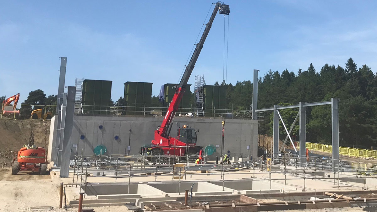
Construction progress July 2021: Lower level – Courtesy of ESD
Conclusions
Within the case study we have highlighted the benefits of the use of standardised designs, digital tools and off-site manufacture, enabling efficiencies to be made in both design, and in construction, which ultimately is for the benefit of customers. The project interfaces have also been greatly enhanced by working in collaboration with Scottish Water. ESD and Scottish Water have successfully managed to navigate a path through all planning, land purchase and regulatory approvals, as well as the construction in an accelerated timescale while maintaining the existing treatment process.


