

Ilkley WwTW (2026)
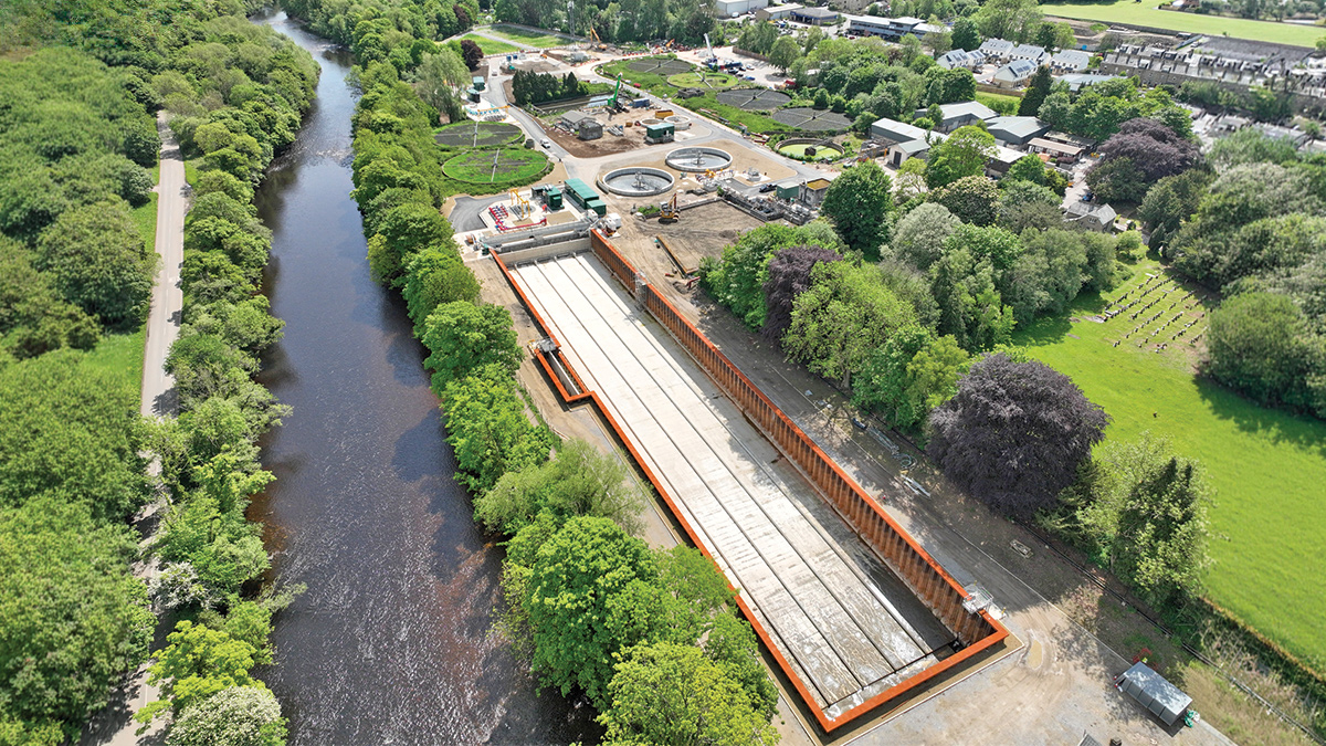
Ilkley WwTW is being upgraded to support bathing water quality improvements in the River Wharfe - Courtesy of Ward & Burke
Ilkley Wastewater Treatment Works (WwTW) is located in West Yorkshire and serves the town of Ilkley and local upstream catchments before discharging treated effluent to the River Wharfe. The site forms part of a wider catchment programme associated with the Ilkley inland bathing water designation, with a focus on improving water quality within the River Wharfe. The primary driver for the scheme is to reduce storm spills to the River Wharfe, supporting the inland bathing water quality at Ilkley. The combination of increased treatment capacity, and controlled storm storage, designed to attenuate flows until they can be passed forward for treatment, allow this goal to be achieved.
Project summary
The upgrades at Ilkley comprise significant modifications to flow conveyance between the upstream CSO network and the WwTW.
These include a new works inlet pumping station to receive all incoming site flows, a 17,500m³ storm storage tank, and new duty/standby inlet screens rated at 300 l/s. Additional enhancements include two new primary settlement tanks (PSTs), a combined secondary treatment feed pumping station to convey flows to the existing trickling filters and a new secondary aerated reed bed, and a tertiary integrated constructed wetland (ICW).
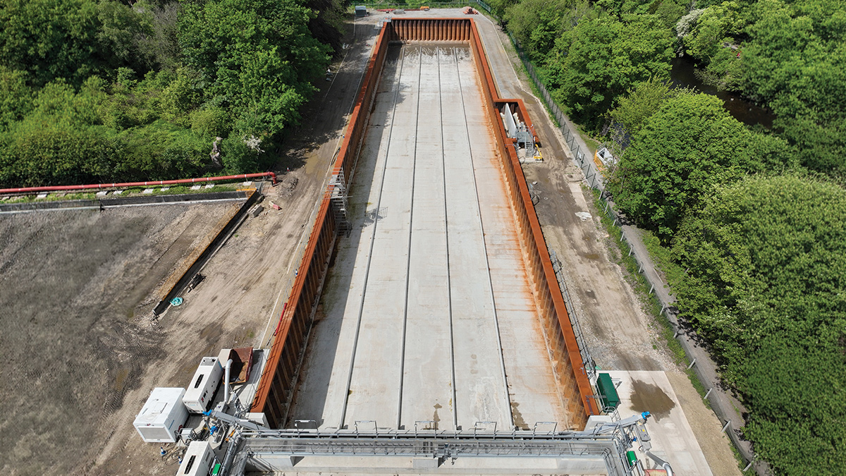
The new 17,500m³ storm tank structure – Courtesy of Ward & Burke
The hydraulic upgrade is significant, with the works being reconfigured to pump forward flows from a dry weather flow of circa. 60 l/s to a new Flow to Full Treatment (FFT) of 300 l/s, increasing from the existing FFT of 114 l/s. During storm events, the system is capable of receiving peak inflows of up to 3,500 l/s. Flows exceeding the 300 l/s treatment capacity are diverted by gravity to the new screened storm storage tank. Once capacity becomes available at the inlet pumping station, stored storm flows are returned and pumped forward for full treatment.
Yorkshire Water’s £41m project commenced on site in July 2024. The scheme forms a key part of wider investment to address storm overflow performance and improve the quality of inland bathing waters. This case study provides an overview of the works delivered by Ward & Burke and its specialist supply chain, focusing on the infrastructure upgrades and process enhancements implemented to achieve storm spill reduction and long-term environmental improvement.
Ilkley WwTW: Designers, contractors & sub-contractors
- Principal designer & contractor: Ward & Burke
- Strategic planning partner: Stantec UK
- Hazard study facilitator: SWECO
- Aerated reedbed specialist: ARM Group
- PST structure design/installation: Shay Murtagh Precast
- Civils & groundworks: Hernon Municipal Engineering
- Electrical installation: EPCC Ltd
- Electrical installation: JMC Electrical Solutions Ltd
- Electrical installation: Lathoa Electrical
- MCC supplier & integrator: BGEN Ltd
- Welders: Nandco Ltd
- Access steelwork design/installation: GT Fabrications
- Transformer supply & installation: Northern Powergrid
- General contracting: Narod Construction
- General contracting: Roland & Sons Civil Engineering
- Drone imaging: Team UAV
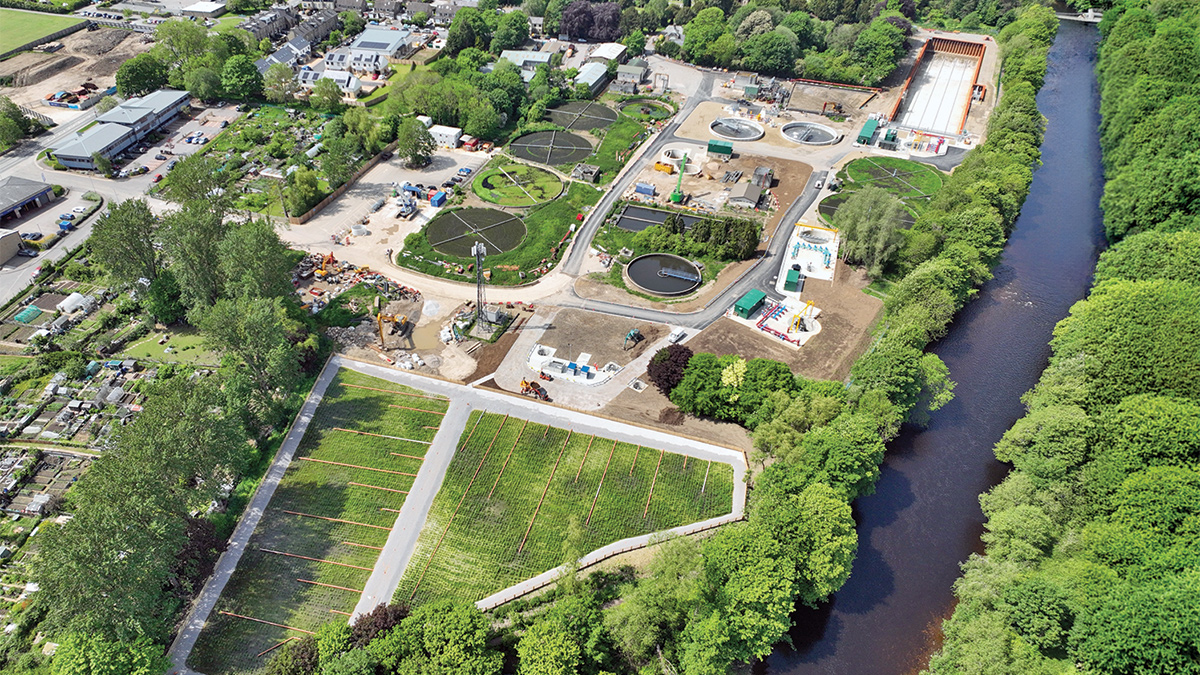
The Ilkley upgrade combines storm resilience, secondary aerated reed bed treatment and wetland tertiary treatment to support bathing water quality – Courtesy of Ward & Burke
Ilkley WwTW: Key suppliers of process plant & equipment
- Inlet & storm screens: Huber Technology
- Storm tank cleaning flushing gates: CSO Group Ltd
- RAM desludge pumps: EMS Industries Ltd
- Pumps: Xylem Water Solutions
- Air blowers: AERZEN Machines
- Valves & penstocks: AFFCO Flow Control (UK) Ltd
- Valves: Cotswold Valves Ltd
- Pipework: Saint Gobain PAM UK
- Pipework: R2M Limited
- Pipework: UTS Engineering Ltd
- Pipework: SC Pipelines
- PST steelwork: Keltec Engineering
- MCC: BGEN Ltd
- Kiosks: Industrial GRP
- Kiosks: Kingsley Plastics
- Lifting gantry: Peter Cassidy (Leeds) Ltd
- Generator: WB Power Services Ltd
- Precast concrete: FP McCann Ltd
- Concrete & aggregates: Holcim UK
- Reed bed stone media: MD Aggregates
Flow transfer from the CSO Pumping Station
A key technical element of the scheme is the modification of the upstream CSO Pumping Station interface and the transfer of flows towards the treatment works. The design includes both low-level and high-level connection arrangements, allowing different hydraulic conditions to be managed through separate flow paths.
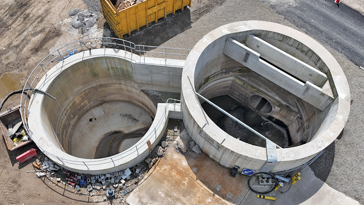
Transfer of all incoming flows to new flow path – Courtesy of Ward & Burke
A low-level pipe connection is provided from the former CSO Pumping Station to the tunnel launch shaft to convey low to average flows forward. In addition, a high-level culvert provides a route for higher flows under storm conditions. This dual-level approach allows the system to manage both average flows and larger storm flows to be passed forward under gravity without relying on a single hydraulic route that could be surcharged.
From the tunnel launch shaft, flows are conveyed through a micro tunnel and high-level culvert arrangement towards the new works inlet pumping station. The site layout to the works includes the launch shaft and reception shaft, which was converted to the works inlet pump station, with a 1200 mm concrete tunnel carrying low to average flows and a 2m wide by 1m high culvert for storm conditions. The addition of these shafts and tunnels provide an additional 3,500m3 of storage within the network further increasing the site’s resilience to storm events.
Works inlet pumping station & storm diversion
The new works inlet pumping station is the primary control point in the upgraded WwTW. It receives flows from the tunnel and culvert system and pumps flows forward to the inlet works. Under dry weather conditions, the pumping station passes forward approximately 60 l/s. As rainfall increases and additional flows are received from the upgraded network, the pump station is designed to increase its pass-forward flow up to the new FFT of 300 l/s.
Flows in excess of 300 l/s are managed through a storm diversion culvert. During storm conditions, incoming flows above the pumping station’s forward transfer capacity gravitate through a high-level culvert and overtop a weir to the new storm tank. These flows are screened before entering the tank.
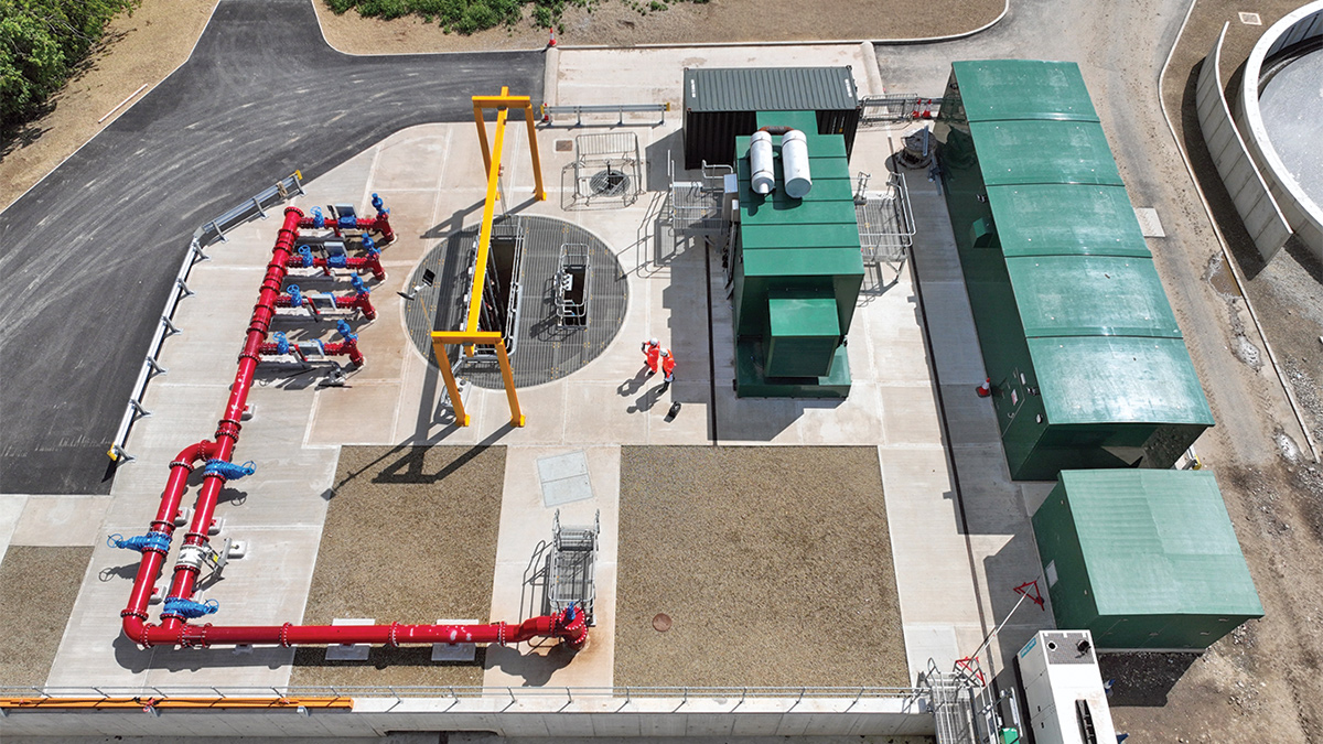
Works inlet pump station and forward flows to treatment – Courtesy of Ward & Burke
This arrangement allows the works to remain hydraulically controlled during high-flow events. The treatment process continues to receive the design FFT of 300 l/s, while excess storm flows are temporarily stored and returned for treatment once capacity becomes available.
To provide additional resilience, a backup generator has been installed to support site-wide power demand up to 1000 kVA. This enables treatment and storm management assets to remain operational during a power failure, maintaining screening, pumping, and flow control capability during periods when treatment continuity is most critical.
Storm tank & flushing gate operation
The storm tank provides the storm storage capacity for the upgraded works. It is a large rectangular storage structure 135m in length, 25m in width, with an average depth of 5.2m across the length of the tank, allowing for a max storage of 17,500m3. The tank is hydraulically connected to the works inlet pumping station so that attenuated flows can be returned when capacity is available.
During a storm event, excess flows enter the storm tank via the high-level culvert and weir, where twin, 8.75m long, 6mm RoK1 perforated mesh storm screens from Huber Technology collect and remove rags from incoming flows.
As the storm tank fills, the associated five flushing gate chambers also fill with retained storm water. These chambers form part of the post-event cleaning strategy for the tank, with the tank divided into five lanes by use of short stub walls to maintain flushing velocity across the 135m tank length.
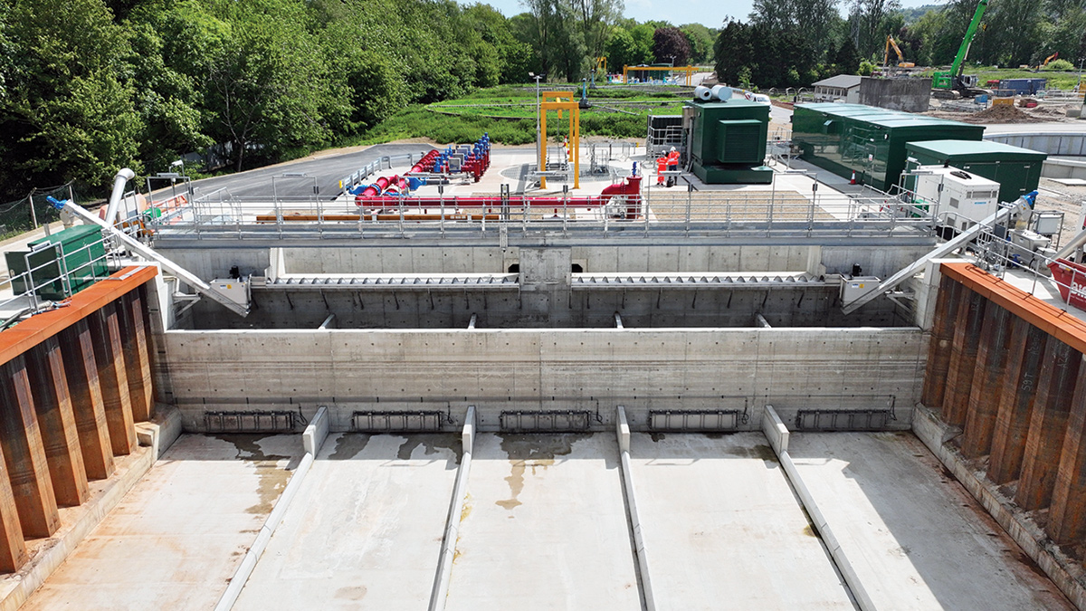
Flushing gate storm tank cleaning – Courtesy of Ward & Burke
After the storm tank has been emptied, the water retained within the flushing gate chambers is released to flush each 5m wide lane of the storm tank. The flushing system, from CSO Group Ltd, provides an automated method of cleaning the tank lanes, reducing manual intervention and reusing storm water as the cleaning medium. This results in low OPEX costs, simple maintenance, and reduced odour issues from storm settlement.
A significant design feature of the storm tank is the use of exposed sheet pile walls. Rather than constructing a concrete retaining wall system, the exposed sheet piles form part of the permanent tank structure. This offers both a carbon and cost benefit by reducing the quantity of concrete required in the tank construction. The exposed sheet pile walls have been designed with a service life consistent with the storm tank design life of 100 years.
This approach provides a practical example of carbon-conscious civil engineering. By using the sheet piles as permanent works rather than temporary works only, the scheme reduces material duplication and makes more efficient use of the installed structural system as the sheet piles were also used as a coffer dam to construct the tank floor.
Inlet works screening
Flows pumped forward from the works inlet pumping station pass to the modified inlet works, where the existing screening arrangement is being replaced with two new duty/standby 45° belt EscaMax inlet screens from Huber Technology. Each screen is capable of handling flows up to 300 l/s.
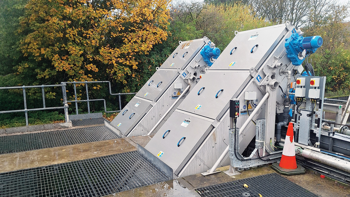
Huber Technology 45° EscaMax inlet screening units – Courtesy of Ward & Burke
The increase in screen capacity, together with the revised hydraulic route into the inlet works required modifications to the existing inlet works structure and associated access steelwork. Sections of the existing channel walls were removed to accommodate the new flow path and the larger screen units.
Tapered channel sections and benching were installed upstream of the screens to manage velocity and improve hydraulic conditions upstream of the screening units. This helps promote even flow distribution across the screen face, reducing the risk of localised settlement and screen blinding.
The access arrangements were also upgraded as part of the works. New access steelwork has been provided to allow safer inspection, operation and maintenance of the new actuated control valves, screens and surrounding equipment.
Primary settlement
The upgraded primary settlement stage includes two new 20m diameter primary settlement tanks (PSTs) operating alongside one existing PST.
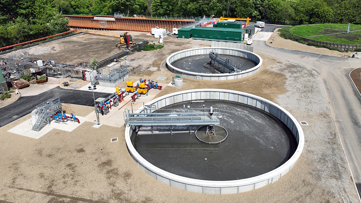
Primary settlement tanks & associated RAM desludge pumping arrangement – Courtesy of Ward & Burke
The addition of two new PSTs increases the settlement capacity of the works and supports the increased treatment capacity. Fitted to the PSTs are steel half rotating bridges.
The new PSTs are integrated into the existing works through a distribution arrangement that allows flows to be split and recombined before secondary treatment pumping. The new PSTs are controlled on incoming flow rate and one of the three PSTs can be fully drained outside of storm conditions to avoid septic conditions.
Sludge removal from the PSTs is handled by the associated RAM desludge pumping arrangement from EMS Industries Ltd, and is fully automated by means of EMS’s adaptive pumping technology.
Combined secondary treatment feed pumping station
Following primary settlement, flows from the new PSTs and the existing PST combine and pass to the new combined secondary treatment feed pumping station.
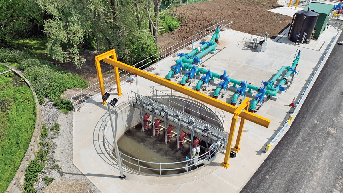
Combined secondary treatment pump station – Courtesy of Ward & Burke
From here, flows are split between the existing secondary treatment stream and the new aerated reed bed. The existing treatment stream includes trickling filter media beds and humus tanks which take existing flows up to 114 l/s, while the reed bed provides additional secondary treatment up to 300 l/s.
The combined secondary feed arrangement allows the works to use both existing and new assets in parallel. This provides operational flexibility and allows flows to be managed across multiple treatment routes. It also reduces reliance on a single secondary treatment process allowing large scale maintenance to be undertaken.
Aerated reed bed as secondary treatment
One of the most sustainable elements of the scheme is the use of a 4,286m2, dual-bed vertical subsurface flow aerated reed bed system as a secondary treatment process. Aerated reed beds are engineered planted gravel bed systems that use forced aeration to support aerobic biological treatment within the media.
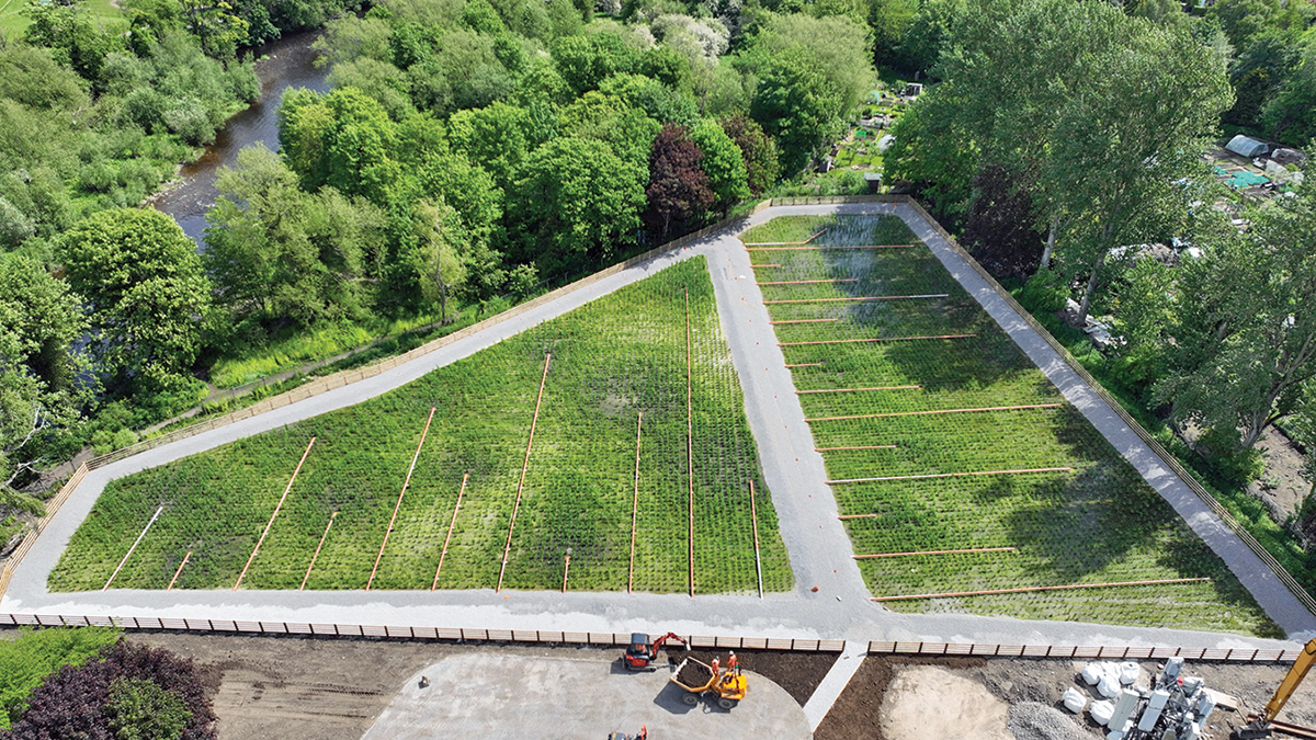
Aerated reed bed nature-based treatment solution – Courtesy of Ward & Burke
Wastewater is distributed across the bed and passes through the media, where biofilm grows on the aggregate surface and around the plant root zone. Air is supplied into the bed by duty/standby blowers from AERZEN Machines, running constantly to maintain aerobic conditions, enabling removal of residual BOD and support nitrification within the reed bed. The reeds provide a resilient vegetated treatment environment, but the principal process mechanism is the combination of media-based biofilm treatment, hydraulic contact and controlled aeration.
The aerated reed beds offer an interesting balance of treatment performance, flow and load variation resilience, operational simplicity, environmental integration and carbon impact compared with conventional secondary treatment options. They can provide a more natural visual appearance than traditional process plant and can be integrated into sites where environmental sensitivity is a key consideration.
Integrated constructed wetland & final effluent outfall relocation
Following secondary treatment, flows gravitate to the Integrated Constructed Wetland (ICW) Feed Pumping Station. From there, flows are pumped under the River Wharfe by means of a directionally drilled main across to the new 16,860m2 free water surface flow treatment wetland or ICW which is made up of six treatment cells for final effluent polishing.
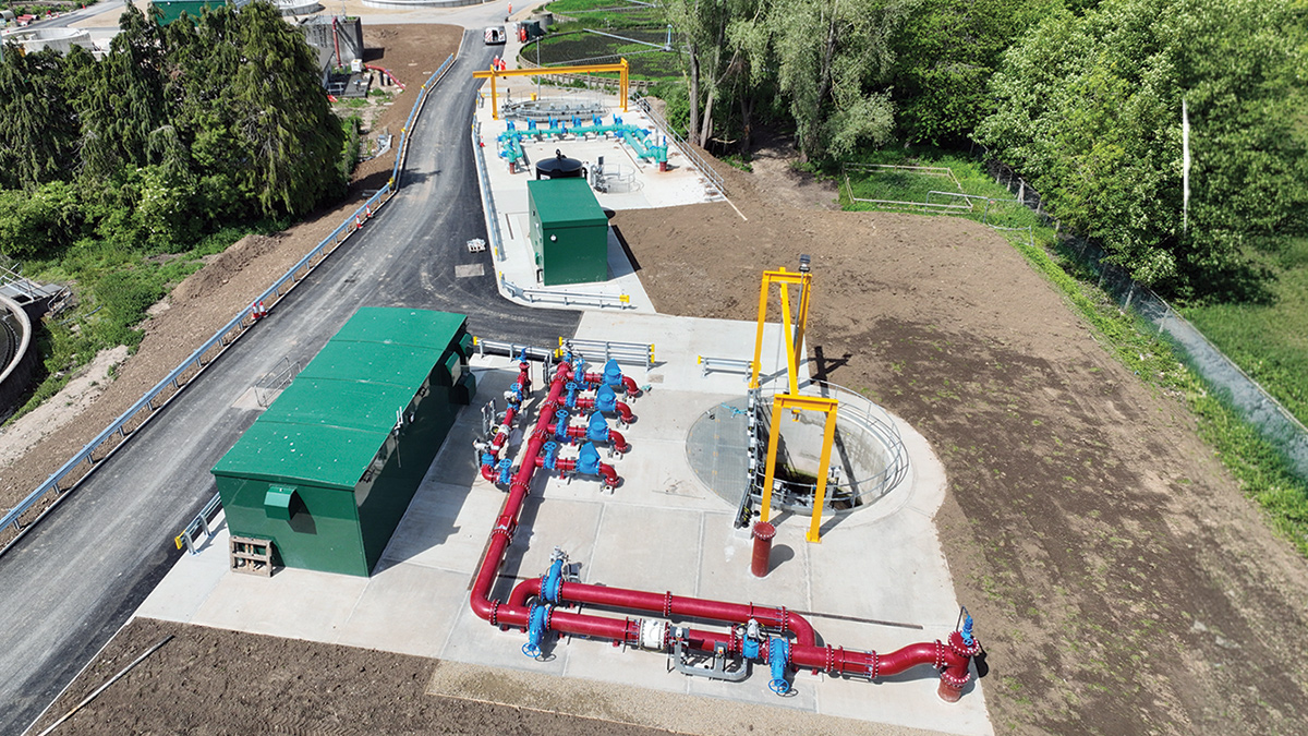
ICW Feed Pumping Station – Courtesy of Ward & Burke
The integrated constructed wetland provides a nature-based tertiary treatment stage prior to discharge. This engineered treatment wetland reduces residual suspended solids, BOD, nutrients and pathogens by maximising the processes that naturally occur within wetlands, such as sedimentation, filtration, accretion and nutrient uptake. Its diversely planted, habitat-rich treatment environment also provides environmental, aesthetic and community benefits. The 29 different plant species bring resilience to its treatment capacity and enhance biodiversity.
The integrated constructed wetland has been designed around an existing pedestrian access route, allowing the scheme to retain and enhance public connectivity through the area. This provides an opportunity to return a nature-rich environment to public use, with the wetland creating a more attractive and biodiverse setting.
The wetland will provide visual and environmental amenity value in addition to its treatment function. The planted cells, open water margins and landscaped areas will create habitats for birds, insects, amphibians and other wildlife, while also improving the character of the surrounding area for walkers and local residents.
By integrating the treatment process with the existing public access route, the solution helps demonstrate how wastewater infrastructure can be delivered in a way that’s sustainable and supports both environmental performance and community value.
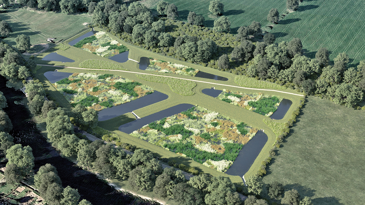
Integrated constructed wetland visual render – Courtesy of Stantec UK
Construction, carbon & maintainability
The project combines civil engineering, MEICA engineering, complex tie-ins, retained operational assets, new process plant and nature-based treatment. Maintaining treatment during construction is a major consideration. Temporary works, flow management, isolation planning and staged commissioning are therefore central to the delivery strategy.
The aerated reed bed and integrated constructed wetland provide a nature-based treatment solution that supports lower-carbon wastewater treatment. By using engineered planted treatment systems rather than solely relying on conventional infrastructure, the scheme reduces the requirement for high embodied carbon materials and energy intensive assets.
The approach also supports more sustainable construction by reusing suitable as-dug material within the works where practicable, reducing imported fill requirements, disposal volumes, vehicle movements and associated carbon emissions.
Conclusion
The Ilkley WwTW upgrade is a technically significant project, addressing UK’s first inland bathing water designation at Ilkley, combining major hydraulic conveyance works prioritising flows by gravity, storm storage, increased treatment capacity, conventional primary settlement, an innovative aerated reed bed secondary treatment process, tertiary ICW treatment and outfall relocation.
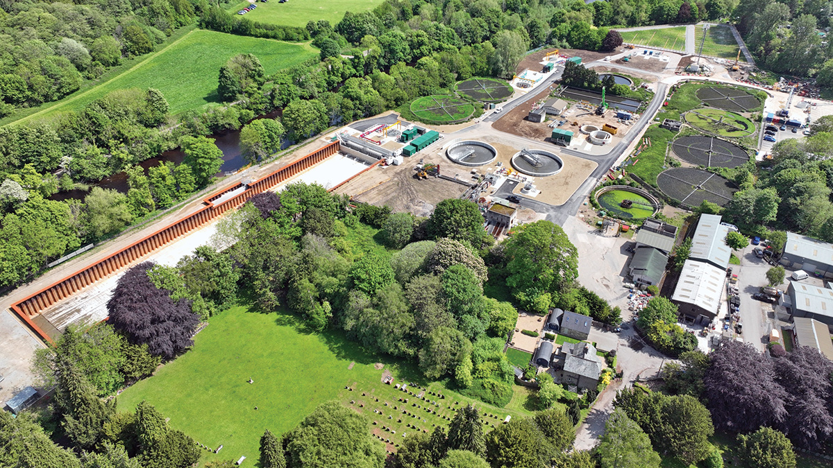
Ilkley WwTW overview – Courtesy of Ward & Burke
As of 31 March 2026, all proposed treatment assets and associated mechanical, electrical and control equipment with the sewage treatment works boundary are commissioned and operational. The upgraded works is now receiving and treating all flows entering the site, with the new process stream providing increased hydraulic capacity and improved treatment resilience.
The ICW is under construction, with completion currently planned for December 2026. Once complete, it will provide an additional final polishing stage before discharge through the new outfall downstream of the bathing water stretch.
A further phosphorus removal scheme is also being developed to meet new phosphorus discharge permits at Ilkley. This future phase will include ferric sulphate dosing upstream of the primary settlement tanks to support phosphorus removal, together with a new sludge storage tank to manage the increased sludge production associated with ferric addition.
Overall, the scheme provides improved resilience for the adjacent water course and bathing water.
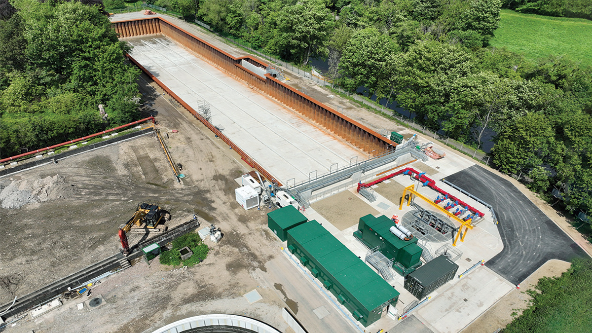
Works inlet pumping station & storm storage - Courtesy of Ward & Burke