
SAL 172 Stormwater Storage: Part 2 (2016)
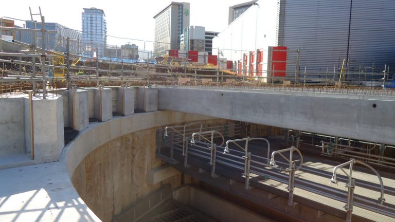
Shaft under construction - Courtesy of GCA JV
The SAL 0172 project formed part of a cluster of schemes in the Manchester area, as part of United Utilities £3.6 billion AMP5 investment programme across the North West. The project was completed by Galliford Try-Costain-Atkins Joint Venture, (GCA JV), as main contractor to United Utilities. Originally covered in the UK Water Projects 2014-2015 edition, this article now completes the story. The 4,500m3 storm detention tank and diversion chamber have been designed and constructed to store storm sewage and prevent the discharge to the local watercourse (the Manchester Ship Canal) in periods of heavy rainfall. The original 2.75m wide x 2m high Victorian sewer is part of the storm spill pipe network that discharged directly into the local watercourse in storm conditions.
Location
Located close to Media City, in Manchester, the detention tank was constructed within a small site adjacent to Weaste Cemetery on one side and industrial units with offices on the other. Construction involved connecting onto the existing culvert which transferred flows into the Manchester Ship Canal; a 21m diameter secant piled shaft at a depth of 24m below ground and twin pumped rising mains routed through a congested industrial estate.
The installation will filter and screen stormwater as well as providing storage. Previously water was directed from the sewer, via the Victorian brick culvert, directly into the Manchester Ship Canal.
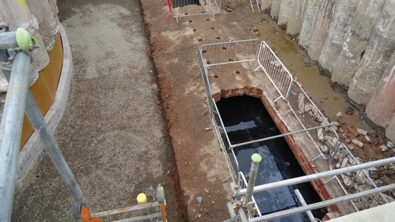
Breaking into Victorian brick culvert – Courtesy of GCA JV
Project summary
In total, 133 (No.) segmental cased piles, 1.18m in diameter, were sunk to form the structures, 80 (No.) piles, each 24m long were utilised for the circular shaft and 53 (No.) x 15.5m long piles for the diversion chamber, which facilitated the connection to the existing Victorian brick culvert, the secant pile construction incorporating pile restraint beams.
Ground conditions at the site were made ground over alluvial deposits and sands and gravels before changing to Sandstone at 12m.
Preparation work for culvert connection included:
- Installation of penstocks across openings into shaft.
- Installation of stop log type brackets to channels at each end.
- Preparation of the bends for installation into open channel sections to suit shape of culvert.
- Preparation of box culverts and add benching to suit culvert profile (following divers inspection).
Installation:
- Cut top of sewer back to arch walls at each end to give 18m distance.
- Leave approximately 1m gap for man access at each end.
- Install sandbags (assumed 1m wide) at both ends.
- Pump out all the debris in the middle.
- Remove sewer between sandbags, leaving straight end saw cut at each end 14m apart.
- Install box culvert at each end.
- Install channel section in the order.
- Install make up piece into channel walls at joint.
- Install fast set concrete into the base at joint.
- Install end walls to top of boxes.
- Remove sandbags and sewer is live again.
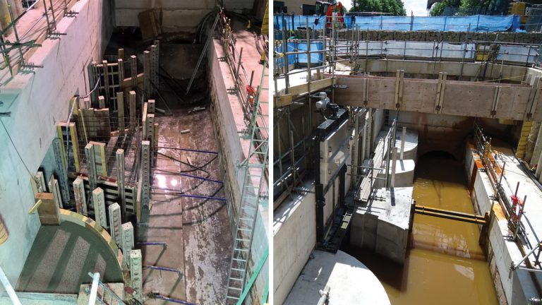
(left) Partial culvert connection and (right) completed culvert connection – Courtesy of GCA JV
Weekly design meetings involved the client and the construction team utilising a fully integrated approach to adapt the design to the construction constraints.
Following completion of the culvert connection, breakthrough divers were employed to determine the actual shape and size of the existing brick culvert itself. They also took measurements to enable the team to manufacture two plates to stop the flow of water on either side of the proposed working area. The diver’s survey confirmed that the culvert was more pentagonal at the base, rather than curved like the roof.
The site team worked 18 hour days (2 back to back 9 hour shifts; 06:00 to 23:00) in lieu of 24 hour working to reduce the impact and disruption to neighbouring hotels in the area whilst these essential works were being carried out. This approach maximised productivity at critical times to mitigate flooding risk from potential storm events and by considering the wellbeing of the work force. This approach also reduced the risk of fatigue and night shift working.
Following completion of the construction of the 21m diameter shaft, the internal construction took place, this included 2 (No.) spill channels each connected to a cross wave static screen with a cross sectional area of 130m2. Central to the spill channels was a Hydrok CWF flushing system for self-cleansing of the shaft. The screens were installed in sections of four rather than the traditional individual method, reducing the number of lifts required from twenty to only five. All the efficiency measures used throughout the construction process have helped reduce the overall costs on the project, delivering it below the original budget.
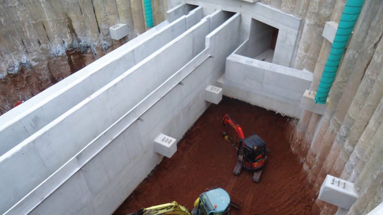
Construction of internal spill channels – Courtesy of GCA JV
Two storm return pumps were located within the shaft together with a scavenger pump alongside a fluidic mixer and associated pipework.
All the screens and walkways were manufactured off site, with the roof prefabricated to suit the ‘as built’ shaft, thus allowing an on-site assembly and installation in a single crane lift. This mitigated the requirement for working at height wherever possible.
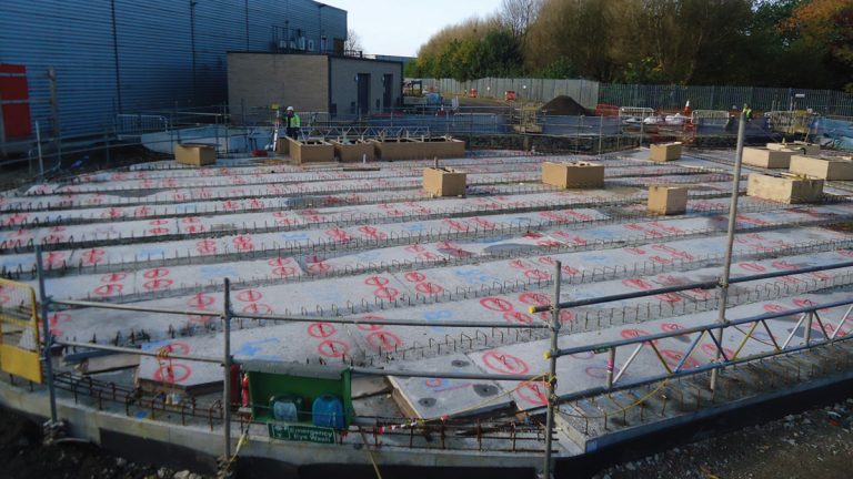
The prefabricated roof was constructed using 32 (No.) pre-stressed beams sat on elastomeric bearings, which are held in position using a reinforced concrete collar with pockets to accommodate the beam ends. The ends were cast in place on their bearings with compressible filler to allow limited movement. The precast permanent formwork slotted onto the top rebate of the beams. At the access openings, the team utilised a system of steel plates to ensure safe working for the steel fixers.
The beams had links protruding up into the in situ roof slab and were tied into the slab reinforcement, enabling the beams and slabs to act as one. A slip membrane was fixed to the top of the slab, with the access road then cast on to the membrane.
The key benefit and success factors of this project were the involvement of key experienced personnel, providing continuity throughout the development of the scheme and established existing working relationships with the client.
Installation of precast roof beams – Courtesy of GCA JV
Health, safety, environment and sustainability
The project has been extremely complex and the team have faced many challenges. To mitigate the risk from falling from height altogether following the installation of the PCC roof slab, the team at SAL 0172 looked at a number of options to achieve this challenge.
Working closely with the temporary works designers, the team developed an innovative solution to mitigate the problem of unguarded voids in the roof slab. Several options were considered initially including netting and in situ mesh, but these were ruled out for various reasons, with temporary steel plates chosen as the most robust option. A total of 18 (No.) plates were specifically designed to be installed with the precast concrete roof sections (permanent formwork), to ensure no unguarded voids were ever present in the roof slab.
Removable lifting points to avoid trip hazards were also included and a detailed construction sequence was devised. The temporary plates were removed at the end of the sequence when the security grille and permanent covers, some of which needed to be oversized to facilitate removal, were then installed.
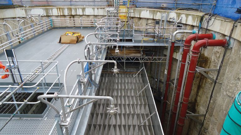
Installation of internal components – Courtesy of GCA JV
GCA JV and United Utilities commitment to health, safety and sustainability was evident throughout our performance on this project.
The weather was closely monitored during critical connection activities, as in the event of a storm surge, up to 9,000l/s had to be dealt with. Innovative construction techniques worked well for managing the water during the connections. They included temporary stop gates and spill alarms to warn the team when the water was at 75% capacity and extensive planning/detailed 3D sequencing of the works.
During the excavation phase the team uncovered a wartime air-raid shelter close to the site access. The team also found a bone during the culvert excavation, meaning works had to be stopped for a period. Fortunately it turned out to be from a horse.
Installation of permanent roof formwork – Courtesy of GCA JV
Summary
This innovative solution is a fantastic example of engineering excellence and collaborative working at its best, with seamless UU and GCA JV teams working closely together from early in the concept phase, to determine the best possible solution to meet the needs of the project.
Despite all the many challenges faced throughout the life cycle of the project, the scheme was completed on time within budget, with flows turned ahead of the Regulatory deadline of 30th June The operational tank now screens any excessive storm water flows before they enter the Manchester Ship Canal and stores any additional water that will then be directed to the treatment works once the storm flows have abated.
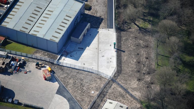
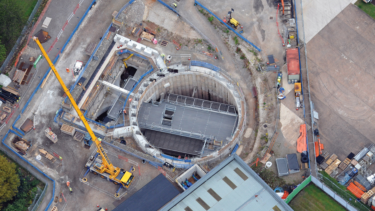
Aerial view showing construction completed – Courtesy of GCA JV
The utilisation of 3D CAD was invaluable to all parties and supported the client with stakeholder liaison and management.
The site has now been handed back to the original landowners and the finish makes the tank almost completely invisible under a car park, apart from the 18 (No.) access lids visible.