

Toome Road, Ballymena, Flood Alleviation Project (2021)
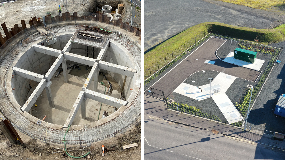
(left) the roof beams and slabs being installed and (right) the finished works - Courtesy of BSG Civil Engineering
Over a number of years, properties in the Toome Road area of Ballymena, County Antrim (Northern Ireland), have experienced both external and internal flooding. The residents had been living in fear of further flooding every time there was significant rainfall and the flooding history also meant they had difficulties and extra expense in getting insurance for their properties. Following investigations and sewer modelling it was identified that the principal cause of the flooding was due to a lack of capacity in the existing combined sewerage system coupled with the inability to discharge storm water to the adjacent river when water levels were high. This required Northern Ireland Water to deliver a solution to resolve the out-of-sewer flooding.
Design
Various design solutions were considered including storm separation, but the existing sewerage system arrangement and topography in relation to river levels made this unviable. The final developed solution sought to provide overflow points on the two combined sewers which passed through the area to a new 850m3 storm attenuation tank located in an area of ground (that had been purchased by NI Water) upstream of the area affected by the flooding. The provision of a new combined sewer was also required. The overflow system was designed to permit screened flows to spill to the tank during significant storm events with a controlled pumped return to the sewerage system when levels subsided, providing protection against a 1-in-30 year rainfall event.
The location of the storm attenuation tank was within the existing river floodplain and the construction would require the realignment of the existing sheet piled floodwall which was concealed within a grass embankment. Compensatory storage also had to be provided within the flood plain by reducing ground levels to satisfy the river authority that there was no resultant loss in the overall flood plain storage.
Removal of existing sheet piled floodwall following realignment – Courtesy of BSG Civil Engineering Ltd
The new below-ground attenuation tank was constructed within a neatly contained site in an existing gravelled area. The 15m diameter and 8m deep tank was designed to be constructed as an in situ cast reinforced concrete (RC) tank using a caisson technique, with the walls cast above ground level before being sunk to the correct formation level. A circular temporary sheet piled wall was installed around the tank to reduce groundwater flows into the caisson shaft and this allowed the bulk of the excavation to be carried out in dry conditions.
In conjunction with the principal contractor BSG Civil Engineering Ltd, it was agreed that the tank roof be constructed using precast beams supported by the tank walls and four internal columns. The roof was to be precast in sections on site prior to an in situ concrete topping being cast on top (the in situ topping improved the waterproofing and kept the precast unit weights down to manageable limits). The use of precast beams and slabs removed the need for any high level formwork.
Toome Road, Ballymena Flood Alleviation Scheme: Supply Chain – Key participants
- Client: Northern Ireland Water
- Principal contractor: BSG Civil Engineering Ltd
- Structural design/project management: McAdam
- Hydraulic modelling: Atkins
- MEICA design: BSG Civil Engineering Ltd
- MEICA design: Wood PLC
- Commissioning engineer: KCG Group Consulting
- Temporary works design: MEA Ltd
- Sheet piling supply: Evans Piling
- Sheet piling installation: BSG Civil Engineering Ltd
- Concrete works: K&J Formwork
- Sewer laying: Bradley & Company
- Traffic management: HBS
- Concrete pipes: Tracey Concrete
- Submersible pumps and mixers: Xylem Water Solutions
- Screens: Eliquo Hydrok Ltd
- Access covers: Cubis Systems
- Booster set: Enisca Ltd
- MCC: Motrol
- Flow meters: Park Automation
- Concrete: Creagh Concrete
- Control kiosks: Carn Plastics
- Ductile iron pipework: Associated Pipeline Products
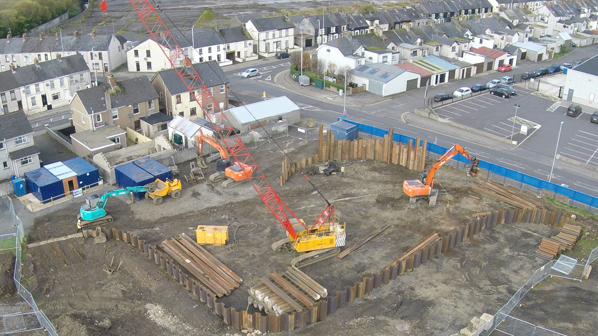
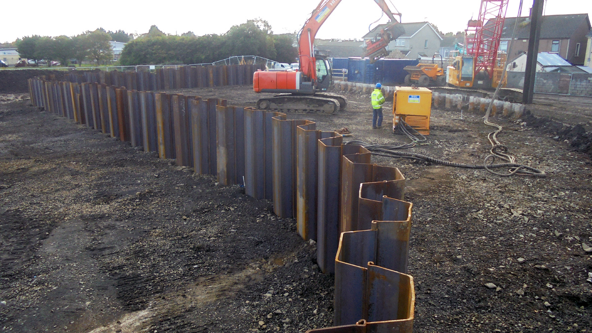
Cofferdam sheet pile Installation following establishment of site footprint – Courtesy of BSG Civil Engineering Ltd
Construction stages
Initial construction activities involved the diversion of 40m of existing 450mm diameter concrete storm sewer to allow the existing sheet piled floodwall to be realigned to free up the footprint for the new 850m3 attenuation tank. The floodwall realignment involved the installation of 123 (No.) 6m long TKL606L GRADE S355GP sheet piles. This phase of the work, particularly the tie in with the existing floodwall, had to be carefully planned to ensure the same level of flood protection was provided to the nearby properties throughout the construction period. With the new floodwall realigned, the existing section was removed allowing shaft construction to start.
The attenuation tank was constructed by sinking a 15m diameter by 9m deep in situ concrete shaft inside a sheet piled cofferdam. A detailed temporary works design for the shaft construction was completed by MEA Ltd. This design involved driving sheet piles 8.5m below ground, a minimum of 1.0m into a dense gravel layer. Piles were initially driven using a Movax side grip pile driver SG45-V and then driven to refusal using a PVE20/VM/2 variable moment vibrator and power pack. During this phase of work, a rigorous quality assurance plan was implemented including pre-condition surveys of nearby properties in addition to continuous noise and vibration monitoring to ensure works were being completed within the acceptable thresholds.
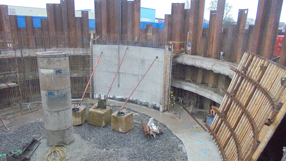
First wall pour – Courtesy of BSG Civil Engineering Ltd
Construction: Phase 1
Phase 1 of the excavation reduced the level within the cofferdam to 4m below ground level and involved the construction of 2 (No.) internal concrete ring beams 800mm x 500mm, one at 1m and the other at 3m below ground level to support the sheet piles. 31 (No.) 300KN SWL, mini piles were also installed to refusal at 1.75m centres on the circumference of the tank to support the concrete collar.
Following phase 1 of the excavation, a structural mud mat was formed to allow construction of the 9m high in situ RC walls which were formed in two 4.5m lifts. To ensure safety during the RC works, a full internal scaffold was erected with working platforms at suitable heights to facilitate the steel fixing and concrete squads. The walls were designed with 8 (No.) beam pockets at the top of wall to receive the roof beams.
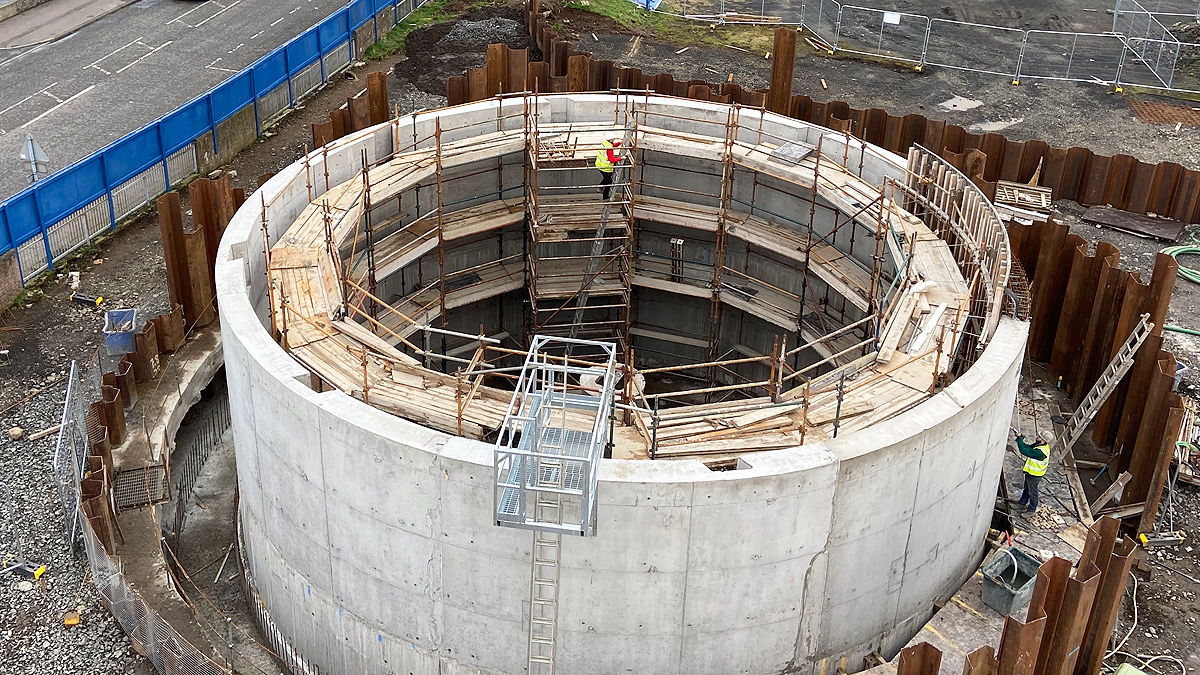
Final wall pour – Courtesy of BSG Civil Engineering Ltd
A critical aspect of this technique was the sinking of the shaft. To control this the first half of the external RC collar (2.5m wide x 2.0m deep) was poured between the sheet piles and the outside of the shaft walls, with polystyrene fixed to the outside of the walls to debond the collar from the shaft walls. This helped to guide the shaft, ensuring verticality during the sinking process, but was also designed to satisfy the anti-flotation requirements during the design life of the structure. The first half of the collar pour involved a 240m3 concrete pour using a 36m boom concrete pump.
Construction: Phase 2
Phase 2 involved undermining the walls and skipping out the material using a 2000L muck skip and 50T crane, with material stockpiled on site allowing it to dry before removal from site. As the walls were undermined, the shaft sunk under its own self weight. This stage of the excavation had to be closely monitored to ensure the shaft sunk evenly around the circumference of the tank. During Phase 2, the available working room permitted on-site casting of the 12 (No.) roof beams and 14 (No.) roof slabs which ensured continuity of work for the RC resources. When the walls had sunk to the required depth below ground, the base was plugged by pouring a 900mm deep RC base slab. Following the plug base pour, a 600mm structural slab, tied into the shaft walls, was then poured along with the second half of the collar pour. The upper collar was also tied into the RC walls to satisfy anti-flotation requirements.
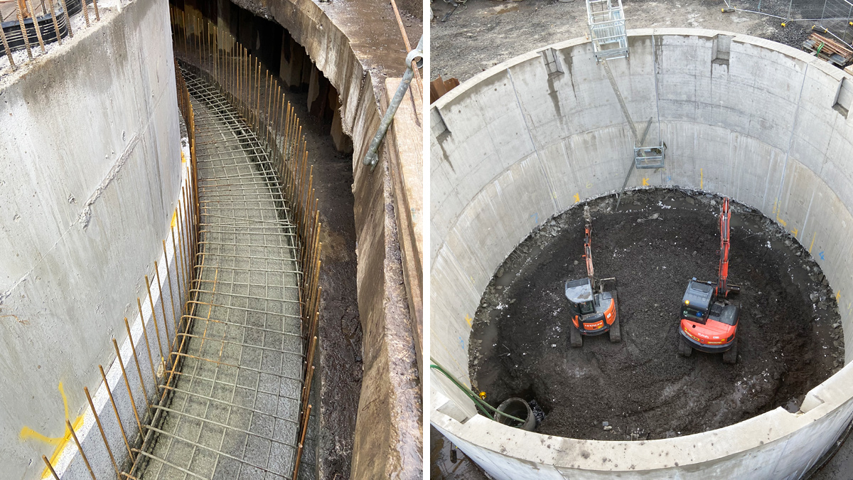
(left) First half of collar pour showing polystyrene to assist the sinking process and (right) Phase 2 excavation works undermining shaft walls – Courtesy of BSG Civil Engineering Ltd
Following the structural base slab pour, 4 (No.) 500mm x 500mm square columns were cast in situ with a 1m x 1m column head to support the roof beams. After sufficient curing of the support columns, the roof beams and precast slabs were then positioned leaving the tank ready for an in situ top pour to the roof. Care had to be taken when positioning the roof slabs to ensure that the openings were set to accommodate the internal MEICA installations.
Mechanical and electrical install
The mechanical and electrical works included a new glass reinforced plastic kiosk containing the MCC which controlled 2 (No.) duty/standby storm transfer pumps and 2 (No.) storm tank cleaners. The flow entering the new attenuation tank is screened by two new Eliquo Hydrok Ltd screens located within new chambers at the overflow points on the existing combined sewers. Overflow Point 1 has a flat static screen installed, designed for a max flow rate of 77 litres/second (l/s) and Overflow Point 2 has a peak static screen installed, designed for a max flow rate of 24 l/s.
The two pumps within the new attenuation tank enable the contents of the shaft to be pumped back into the existing gravity sewer on Wakehurst Road, which transfers flow towards a local pumping station and then onward to the treatment works. An ultrasonic level sensor installed within the gravity network on Wakehurst Road is used to inhibit the pumping regime. After a storm event and the level within the gravity sewer has subsided, the duty/standby pumps will begin to empty the tank with a peak flow rate of 30 l/s.
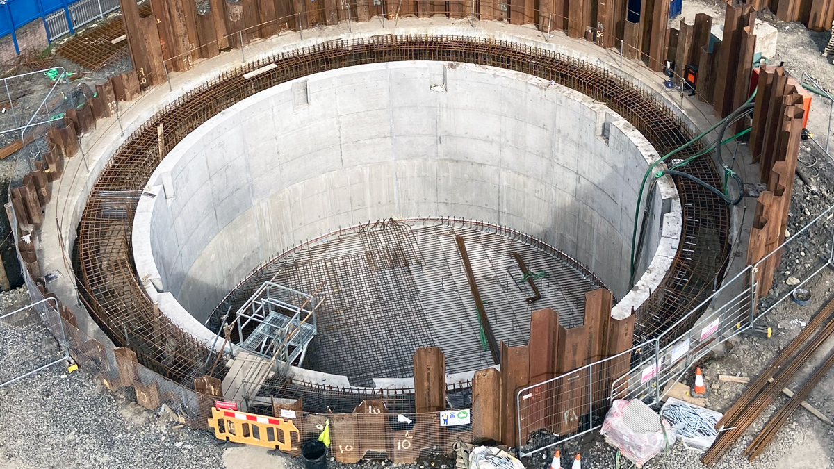
Shaft sunk to final levels and preparation for structural base pour ongoing – Courtesy of BSG Civil Engineering Ltd
Toome Road Flood Alleviation Scheme: Key figures
- 73m existing sheet piled floodwall diversion.
- 15m diameter shaft tank construction to provide 850m3 of offline storage.
- 31 (No.) 300KN SWL, mini piles to support RC collar.
- 450m3 RC collar to satisfy anti-flotation design.
- 2.7m diameter valve chamber and 1.8m diameter flowmeter chamber.
- Maximum lift for install of roof beams and slabs was 6.5t.
- 216m of 300mm uPVC gravity sewer upgrade.
- 77m of 375mm diameter concrete overflow pipework to spill screened sewage to the new storm attenuation tank.
- 25m of 180mm SDR17 pumping main to return flows to the existing system when the levels permit.
- All pipework laid by open-cut method at depths in the range of 2.5-3m.
Planning and communication
From early development of the scheme it was apparent that there would be significant impact on the general public and businesses in close proximity to the site. Throughout the project, strong communication links with the local community and elected representatives were maintained with regular update letters issued. A number of open evenings were held both during the design and construction phases to allow stakeholders to raise any concerns or queries with the project team about the scheme. A community site visit was also hosted during construction which afforded an opportunity for local residents who would benefit from the finished scheme to visit the site and witness some of the processes involved.
Visits were also completed with local primary schools in the area to provide more information about the project along with helping to inspire the next generation of Civil Engineers. Graduate and placement students from BSG Civil Engineering Ltd were also invited to the site to enhance their own construction experience and knowledge. All these measures helped the scheme achieve a ‘Performance Beyond Compliance’ Award as part of the Considerate Constructors Scheme.
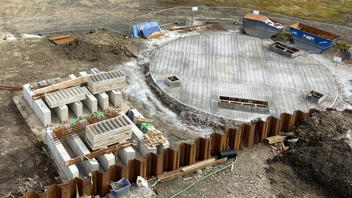
Roof beams and roof slabs prefabricated and cast on site during Phase 2 excavation – Courtesy of BSG Civil Engineering Ltd
Successful delivery
The project team had to ensure successful delivery of the scheme in the midst of the Covid-19 pandemic which resulted in a brief pause to construction during the first lockdown in March 2020. Site procedures and methodologies were modified to ensure the safety of the workforce and the general public were maintained and construction on this essential site quickly resumed.
The attenuation tank site was finished with an asphalt access and turning head, concrete paths around the tank for maintenance and operational access areas and a gravel finish with low maintenance landscaping. There has been substantial tree and shrub planting and the site is largely screened on two sides by the realigned flood wall which is planted with dwarf perennial ryegrass to minimise cutting requirement.
Following testing and commissioning, the new attenuation tank and infrastructure has been in successful operation since October 2020 and as result, the risk of any future flooding has been substantially reduced, providing a significant number of properties in the area with a much greater level of protection.