
Deephams STW – A630 Major Upgrade (2018)
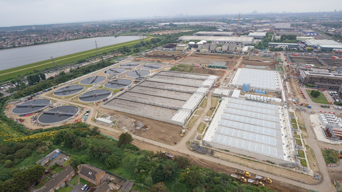
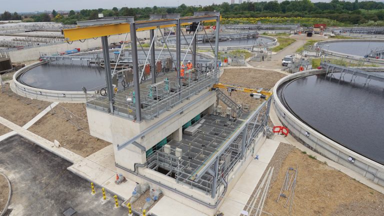
The replacement works in operation - Courtesy of AMK
Thames Water’s Deephams Sewage Treatment Works (STW) is located in Edmonton, North London and treats a 989,000 population. Three drainage catchment areas of Lea Valley, High Barnet and Tottenham flow to the works, the ninth largest plant in the UK. The original effluent treatment process was built between 1956-1966 and had been updated at various times over the years, with the most recent changes including a tertiary treatment plant in 2008 and the Inlet Works Improvements, designed by AECOM and built by J Murphy & Sons and Nomenca Ltd in 2011. This latter project was published in Water Projects UK 2011 and showcased a 17m deep secant piled pumping station, the deepest in the UK at that time, new storm tanks and fine screening structures elevated above the new storm tanks. As part of the AECOM, Murphy, and Kier (AMK) joint venture, AECOM designed the A630 Deephams STW Major Upgrade for Thames Water to replace the entire sewage treatment stream while the works remained operational. AECOM provided civil, structural, hydraulic, MEICA and process engineering design, working with Thames Water through both the pre-construction and design/build contracts.
Project brief
The key aims of the Deephams A630 project were to improve the final effluent quality discharged to the River Lee, increase capacity to manage future population rises and reduce odour emissions.
The new treatment stream required a brand new flow to full treatment (FTFT) pumping station, primary settlement tanks (PSTs), activated sludge process (ASP), final settlement tanks (FSTs) and tertiary treatment plant (TTP). Additionally, two further pumping stations were required for returned activated sludge (RAS) and stormwater, plus flow distribution structures to distribute flow evenly between the process stages. The existing inlet works screening facilities needed to be extended with the addition of medium bar screens and the whole inlet works was to be covered to reduce odour emissions. Along with the treatment structures, the works included odour control plant, improvements to waste gas recovery, energy generation and new facilities for operations staff.
Construction phasing
The existing sewage treatment process was split into three streams, A, B and C. In order to construct the works, it was necessary to treat sewage using only two streams, B and C, to enable demolition of stream A and building of a replacement stream. The demolition and construction works was split into phases to ensure that the works remained operational throughout.
Early works phase: The existing plant performance as it stood would not have been able to meet final effluent consent if run on two streams for an extended period of time. AMK provided a full hydraulic design optimisation and programme of early bolstering works to return the 1960s plant to maximum efficiency and then verify through testing that the works could function on two thirds of the treatment streams.
This work included installing v-notch weirs on final settlement tanks to restore lost capacity of effluent flows caused by differential settlement of individual tanks. Hydraulic losses in culverts and pipes were reduced by freeing up throttled and seized penstocks and by removing sediment build up. A brand new tertiary treatment plant was built to improve the quality of final effluent and give an added level of security for the next (temporary) phase with two stream operation, to ultimately become part of the permanent works.
Integrated fixed film activated sludge (IFAS) media was installed in the existing ASP tanks to increase the area of biological mass used in the aerobic stage of breaking down organic debris. This increased the quality of the water passing to the final settlement stage and thus helped two streams treat the flow of three.
Over a period of testing, AMK worked with Thames Water’s Plant Operators, providing operational and commissioning support to ensure the works could function on the two streams and achieve the required effluent quality to avoid consent failures.
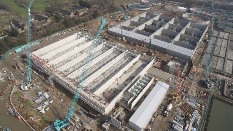
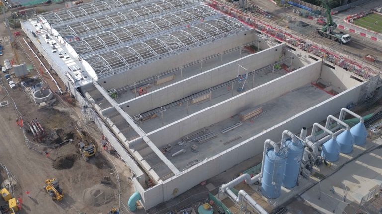
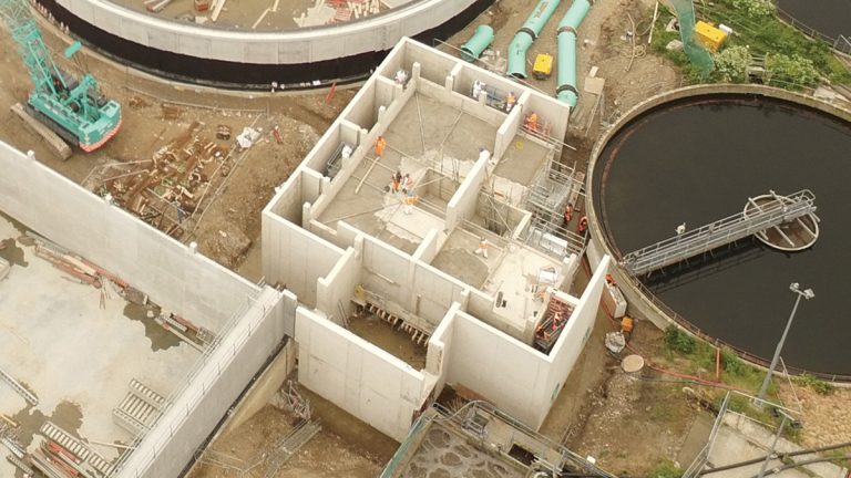
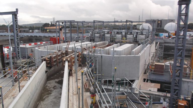
Stream A replacement process stream under construction – Courtesy of AMK
Temporary phase: This involved demolition of stream A and subsequent construction of the new treatment stream and FTFT pumping station. Streams B and C remained in service running approximately 60/40 flow split with IFAS media and new tertiary treatment operating to provide the quality of effluent required from only two streams.
Intermediate phase: This involved commissioning of the new stream with up to 75% of the full works design flow. Two thirds of the IFAS cages were transferred to new ASP tanks. Stream B was decommissioned, with Stream C treating the balance of influent flow by gravity. With the first phase of works operating satisfactorily and handed over to Thames Water, Stream B was demolished and the remaining PST, ASP and FST structures were constructed.
Permanent phase: The Stream B replacement was commissioned, with remaining IFAS cages transferred to the new ASP tanks, before Stream C could be decommissioned. The entire stream is now running with the new hydraulic profile.
Due to the plant layout, there are no longer three discrete streams of treatment as such. Instead, the flows combine and split between PST, ASP and FST stages, with a certain level of redundancy across all process units.
Key design features: Inlet works Improvements
The exposed inlet works structures and channels were covered to substantially reduce odourous emissions from the original treatment works. New medium bar screens were installed to replace existing fine screens on the Lee Valley and High Barnet inlet sewers. Two odour control plants were installed in the inlet works to extract odorous air from beneath the covers for treatment. Additionally, a new overflow structure was provided to the storm tanks to allow excess flows to be diverted hydraulically from the new treatment stream.
Flow to full treatment (FTFT) pumping station
The new treatment stream hydraulic profile is elevated above ground level to provide greater hydraulic head to overcome future river flood levels and to prevent backflow from the river. A 6m3/s single trench style wet well pumping station was designed, with 6 (No.) canister pumps suspended from above with bellmouth discharges to an elevated discharge channel to feed the new primary settlement tanks.
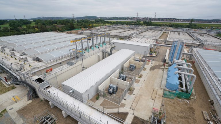
FTFT pumping station area, including air blower building and odour control in foreground – Courtesy of AMK
The design of the wet well originated from the USA and is a first for Thames Water. The slim width of the trench and consequent forward velocity transports debris to the active pumps to reduce build up of sediment and hence reduce the need for maintenance access for cleaning. Furthermore, the self-cleansing design and extractable canister pumps eliminates the need for man-access or a second wet well, hence mechanical downtime can be eliminated. More importantly, the necessity to put men in hazardous spaces is eliminated.
The new pumping station is located at the end of the original PST feed culvert, a fairly long and shallow gradient twin box culvert; hence a cleaning cycle can be periodically implemented where the pumping station sump level is drawn right down to scour any settled solids in the upstream culvert to the pumps. The wet well was tested with physical models built by Hydrotec Ltd. Built in one of the old primary settlement tanks, the structural designer was presented with the challenge of restricting the footprint of the structure to within the tank (to reduce extensive temporary works outside of the old tank), whilst designing acceptable ground bearing pressures and limiting settlement. The design required the use of concrete with lightweight Lytag aggregate to reduce the overall weight by 25%.
The top of the pumping station wet well is tapered in cross section and the inlet has a steep ramp that is normally below the water level. Triangular fillets eliminate turbulent conditions in the wet well, vortice formation and help transport debris to the duty pumps. Access to inspect the sides of the wet well from ground level is provided at ground level with hinged chequer plates that can be folded back for pressure washing of any fats, oil or grease build up.
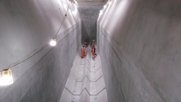
Flow to full treatment pumping station wet well – Courtesy of AMK
Reuse of existing structures
AECOM provided sustainable design solutions through material reuse and incorporated existing assets into the design. All soil and structural concrete waste remained on site and was recycled for backfill. Zero soil or concrete was taken off site, thus reducing traffic movements, noise and vehicle pollution.
Existing concrete structures such as the old PSTs and FSTs were demolished to below ground level and all concrete material recycled as structural fill material. New activated sludge process (ASP) tanks were built inside existing tanks to reduce excavation and temporary works. The original internal lane structure of the ASP was demolished, whilst the external walls were retained and used as the outside shutter of the new ASP tanks to ground level.
The new tank walls extended above ground the same height again. The tank bases were excavated to install new subsoil drainage pipes underneath, and groundwater is only pumped down when a tank is to be removed from service.
Primary settlement tanks
Primary tanks are supplied by a tapered inlet channel and multiple inlet to flocculation chambers. Hydraulic modelling was carried out to ensure even flow distribution. A scum baffle is installed before the outlet weir and scum is removed using a rotating trough system to the drainage to the head of the works. Chain of flight scrapers were chosen to remove settled solids from the tank. This is removed by pumping from hoppers.
PST and odour control – Courtesy of AMK
The new primary settlement tanks were built over the footprint of the original tanks after the original tanks were largely demolished and the original formation level had been raised with crushed concrete from the old structures. Flow distribution is via an elevated, tapered inlet channel. Precast concrete components were used extensively to form a 70 tonne hopper trench for each tank, as well as 13m long scum baffles. Man access flanges were designed in at ground level in the PSTs to enable access when drained, from ground level, eliminating access from heights. Discharge is via weir channels at the end, discharging via a common channel to the ASP flow splitter. Tanks were covered using aluminium frames and retractable fabric covers, connected to the odour control system.
Activated sludge process tanks
Effluent from the primary settlement tanks mixed with return liquors is split into the ASP tanks and initially passes through an anoxic zone with mixers. This passes out into the aerobic zone, where the floor is covered with a grid of air diffusers. Three baffles in the tank promote plug flow through the tank, discharging over the end weir into the outlet channel.
The initial design of the new tanks was in situ reinforced concrete, constructed within the confines of the old tanks as an external shutter. However, steel fixing for the first four tanks proved time consuming in the corners because there was no access to fix the second layer outside horizontal steel rebar to the main bars below ground level. Fixing took more time because bars had to be carefully threaded behind the main bars.
For the second set of tanks, the design was changed to fabricate the wall corners and junctions as a precast item off site. The in situ reinforcement design was transposed into discrete corner pieces with couplers on each face, with up to four layers of bars, constructed off site, delivered in time and landed in prepared positions. Each precast concrete corner piece was 8.5m high and weighed 25 tonnes. Threaded bars were then screwed into the couplers on site and the wall steel fixing continued from corner to corner. This was both, safer and saved weeks of construction time. Precast concrete was used for the main baffle wall panels and support columns, as well as the IFAS guide columns. Columns were installed using corrugated grout pipes in the precast components, grouted on to stainless steel starter bars.
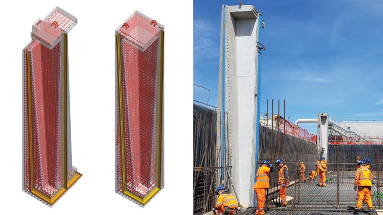
(left) ASP precast middle unit and (middle) precast corner unit and (right) ASP precast corner pieces being installed – Courtesy of AECOM Ltd
As the new ASP tanks were commissioned, the Eliquo Hydrok Ltd IFAS media was transferred by crane from the existing tanks to the new tanks. Due to the size of the tanks and the weight of the cages once populated with biomass, the size of crane required, to get the reach across the entire installation of cages, was a 500 tonne capacity with 50m jib and 60m luffing jib on top. Permanent crane slabs were provided for future removal of cages. In the long term, only occasional removal of cages may be required for media renewal.
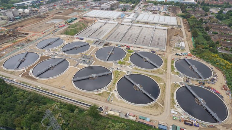
Final settlement tanks
Final settlement tanks were 45m diameter constructed using precast post tensioned concrete panels installed on a flat, piled base slab. Sludge from the tank floor is extracted by a rotating bridge with vacuum header, which discharges via an actuated bellmouth chamber and gravitates back to the RAS pumping station. Final effluent from the tanks discharges to a common culvert towards the new tertiary treatment plant. The tanks are protected from the downstream river flood level by hydraulic breaks, setting the FST outlet weirs above the maximum design flood level. Tank drainage was provided using sump pump out connections for mobile pumps and discharge points to adjacent tanks, instead of providing a long run of tank drainage pipe to the head of the works.
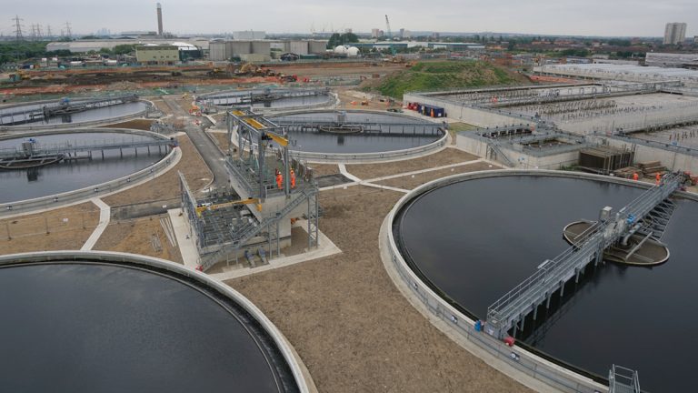
Final settlement tanks and RAS pumping station – Courtesy of AMK
Hydraulic flow distribution
Thames Water wanted to achieve a ±5% or better flow distribution in the treatment stream between all units in service so that all tanks were presented with an equal flow split, regardless of which units were in use. As the new process treatment was above ground, all connections had to be made with underground pipes and flow distribution was designed by weir structures.
From the primary settlement tanks to the activated sludge process, 2 (No.) 2,400mm diameter pipes feed a flow splitter structure with six weirs each feeding 1,400mm pipes to the tanks. Two additional weirs were provided for future expansion. From the activated sludge process to final settlement required a ten-way flow splitter, which again was done by weir distribution. Physical modelling by Hydrotec Ltd was done for both of these structures and achieved better than ±5% across all units.
One complication that arose with the FST distribution structure was that only 75% of the footprint could be built and commissioned in the intermediate phase because the remaining 25% clashed with an existing tank that could not be demolished until Stream B was decommissioned. Six of the ten final settlement tanks were required to be commissioned in the first phase to treat up to 75% of flow; however, the feed pipe to the sixth tank had to be located in the missing 25% of structure. The design solution was a temporary box channel fabricated and suspended over the partly constructed structure to supply the sixth FST. Only once stream B was demolished could the remaining quarter of the flow splitter could be built and commissioned to feed the remaining four tanks.
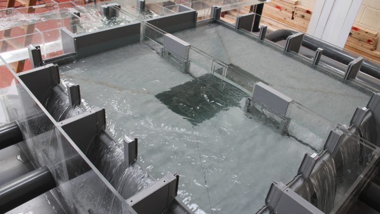
Final settlement tanks ten-way flow splitter – Courtesy Raoul Nardin, AECOM Ltd
RAS pumping station
The returned activated sludge (RAS) from the FSTs gravitates to the new 3m3/s RAS PS twin wet wells, where canister pumps lift the sludge to an elevated discharge chamber. From here, the sludge flows by gravity back across the site through a 1,900mm diameter pipe to upstream of the ASP process, to be blended in at the flow splitter. This gravity design was a result of a challenge to eliminate a pumping main solution with expensive valves and also by changing to a gravity solution, the operating costs were reduced significantly.
RAS Pumping Station with FSTs in background – Courtesy of AMK
Odour control works
All existing inlet works except the storm tanks were covered with GRP or aluminium covers to reduce odour issues in the vicinity of the works. The original Tottenham Low Level pumping station wet well, constructed in 2012, was covered with GRP covers. Existing grit channels, bar screens and fine screens were enclosed, generally by retrofitting to the top of the structures. New inlet channels and primary settlement tanks were covered, the latter with retractable covers. The flow distribution structure feeding the ASP units was covered, as was the anoxic zone of the ASP. This concluded the covering of the most odorous areas of the old and new works.
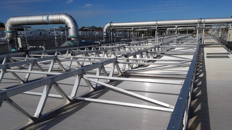
ASP anoxic zone covers – Courtesy of Raoul Nardin, AECOM Ltd
Three odour control unit (OCU) plants were installed to draw clean air into the treatment tanks and treat the odorous air. The plant comprises bio-trickling filters, air fans and deep bed carbon filters. The bio-trickling filters contain lava rock media to remove the bulk of odorous elements such as H2S, ammonia and sulphur by biological action. The resulting effluent is drained back into the treatment stream. A deep bed of caustic impregnated carbon filters removes odour causing elements further. The carbon media is replaceable once it becomes ineffective and H2S or odour increases at the exhaust. Each of the three plants has a number of duty centrifugal fans to draw air from the various parts of treatment, to the plant. Treated air is discharged to the atmosphere via an exhaust stack. Instrumentation continuously monitors the exhaust emissions to ensure the stringent requirements for odour reduction are met.
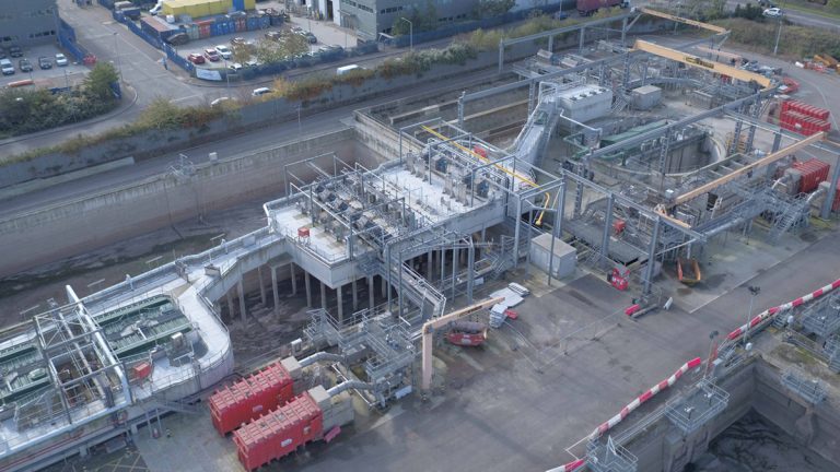
Tertiary treatment plant (TTP)
The existing TTP had a submersible pumping station to lift the flow from the final effluent culvert at ground level up to the filter assembly, providing the necessary driving head. To meet the new discharge consents of the A630 project, AECOM designed a new plant with twelve Mecana disc filters in two banks of six with a weir distribution system to treat up to 4,300 l/s average works flow. The existing pumped plant has been retained as supplemental capacity to deal with flows over this level, thus eliminating much of the existing pumping cost. This saved Thames Water the write off value of the existing plant that was not life expired, the cost of demolition and reduced the cost of the new plant. Backwash flows are transferred by a backwash pumping station to the head of the works for treatment.
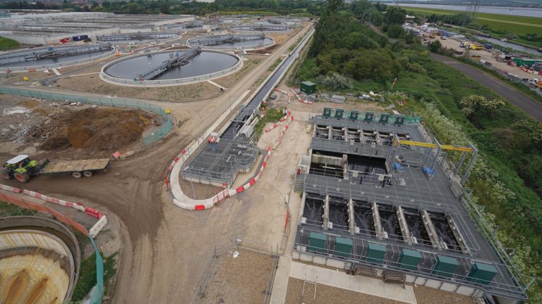
New tertiary treatment plant – Courtesy of AMK
The new plant can bypass back to the final effluent culvert if filters become blocked or are taken out of use; in which case the final effluent goes on to the old plant. Alternatively, the new plant can forward bypass hydraulically over the emergency weirs if necessary. The downstream plant feed has been modified to take whatever flow bypasses the main plant. Should both plants reach capacity, final effluent can be diverted to the river. These aspects of operational flexibility and failsafe were built into the design to solve the engineering challenges and enable the existing plant to be retained.
The new TTP was built in the early works phase in order to reduce the risk of water quality consent failures during the Temporary Phase. However, the permanent phase of the design required the TTP to be at a higher level than could be gravitated to by the original works. A temporary pumping stage was built into the design to lift flows from the streams in use until the two new streams were built and commissioned to the final hydraulic profile. This was done by building in a temporary soffit in the inlet chamber where four canister pumps were installed. This was sealed to create a false floor, above which flow discharged by bellmouth and could gravitate through to the permanent hydraulic profile of the filters.
Once the new treatment stream was complete, the entire stream ran by gravity and the temporary pumping stage was no longer required. The pumps were redeployed to the new storm pumping station, saving the purchase cost of four of the eight canister pumps needed there. The temporary floor slab was removed as the TTP plant reverted to full gravity flow
Three quarters flow splitter – Courtesy of AMK
High voltage and low voltage electrical
The works included a new high voltage ring main and control building, standby power generation and new combined heat and power (CHP) installation to recover energy from waste sludge digestion gases. Numerous control buildings and transformer installations were required for new and existing plant, including all new and existing pumping stations, aeration blowers, scrapers, mixers, tertiary plant and odour control plant. Additionally, a new operations control room was constructed on site to bring the works up to date and provide a central elevated viewing facility for the operator of the site.
CHP and standby generation
Waste gas recovered from the sludge digestion processes is captured and conveyed to the CHP area, where the new containerised CHP engines create electricity from the gas to feed the site and back into the grid. A new waste gas flare ensures that gas that cannot be stored is burnt efficiently to comply with environmental emission limits. Four new generators and fuel storage were installed in a new facility on site to provide sufficient power to run key equipment on site in the event of power failure.
Stormwater pumping station
The design team developed an unusual method of protecting the storm tanks from high river levels and to ensure that the works could discharge the full 10m3/s storm capacity when the river flood level is high. There was a lack of driving head in the existing storm treatment stream to overcome the future design river flood level and so the solution required a pumping station to be added.
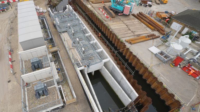
Stormwater pumping station – Courtesy of AMK
However, it was deemed that a conventional wet well in the storm channel was undesirable as it would be static for much of the time, plus the current storm treatment stream could still gravitate at maximum flow at the current river level, so it was not necessary to pump below that. A solution was required that only introduced the pumping when the river level was higher.
The solution was an in-line pumping station, utilising the long storm tank outlet culvert as the storage buffer, rather than a conventional wet well. In dry weather conditions of zero flow, the storm outlet channel level is determined by the downstream river level. Initially, any excess storm flows pass from the storm tanks to the river unassisted through the central culvert of the pumping station by gravity. In the event of an increasing river level, penstocks at the downstream end are closed to protect the storm tanks and site from flooding.
As and when the storm tanks are filled and the works storm flow runs to river, the 10m3/s capacity canister pumps will lift the flow to discharge to side channels that bypass the closed penstocks. This gives the works the ability to overcome the future storm river level at maximum output and protects the site from flooding.
The side channels invert are designed to be above the normal river level in dry times, to reduce standing water. As is the case with the other pumping stations designed on this project, the use of canister pumps eliminates man access for maintenance and enables pump extraction without disruption to operation.
The pumping station was modelled physically and as a result, the design developed to include flow conditioning measures and surge protection weirs in the event of total pump trip during a storm event.
The pumping station was initially designed as in situ construction, but converted to a hybrid precast and in situ solution. The existing storm channel was diverted temporarily with a sheet piled channel, to enable construction in a ‘dry dock’. The walls of the existing channel leaving the site were raised to provide the necessary river flood level protection to the site.
Tottenham low level medium screens structure
The existing Tottenham low level inlet works fine screens and detritors were installed on an elevated structure above new storm tanks as part of the previous inlet works project with J Murphy & Sons, Nomenca and AECOM (see UK Water Projects 2011 and Concrete Society Awards 2012). The addition of a new medium bar screens facility was deemed necessary to reduce persistent screen blinding issues with the screens installation.
Tottenham low level inlet works showing elevated medium bar screens and fine screens structure, centre – Courtesy of AMK
One of the challenges here was designing the new screening structure to be constructed either side of the existing elevated screens feed channel, whilst keeping it live with minimal shutdowns to break into and modify the original structure, above the existing storm tanks. Additionally, there was very limited space in which to install the screens between existing and the inlet chamber.
The existing structure was extended by building two screen channels on either side and then breaking in at the upstream and downstream ends and making good the connections. Mini piles were required to provide additional ground bearing capacity. Plant access and craneage had to be from the storm tanks below that were taken out of service.
The design included full hydraulic bypass to allow the bar screens to bypass to the downstream fine screens in the event of blockage. It also converted the original centre channel to a spare screen channel for the future, with all new flow passing to the two new screens on each side. Physical modelling was carried out to ascertain that a good flow balance could be achieved between all channels in use, and also to ensure that the open area between the old and new screens did not suffer adverse deposition due to low velocities. This was a success and the flow balance proved to be better than ±5%.
Tottenham low level inlet works – Medium screens upstream view – Courtesy of AMK
Sludge
A number of improvements were made to the sludge process stream as part of the project. All filtrate and backwash flows from sludge processes were separated from the site drainage network and returned upstream of the primary settlement tanks via a dedicated return liquors pumping station and pumping main. Secondary digester tanks were fitted with covers and gas extraction plant, to recover additional waste gas from the digestion process to be used in the CHP engines. Primary settlement tank sludge and scum is returned via new dedicated pumping mains to the sludge treatment area, along with surplus sludge from the RAS pumping station. Other improvements included replacement sludge screens and a sludge import facility.
Pipework
The main conduits for process flows used epoxy coated carbon steel pipe. Pipe sizes ranged from 1,200mm-1,400mm for the final settlement tank feeds, 1,400-1,900mm for the returned activated sludge feed and up to 2,400mm for the PST to ASP flow splitter feeds. After assessing numerous pipe coatings and alternative pipe materials, carbon steel with 3M Skotchkote 206N epoxy coating was deemed to be the most suitable combination, offering the most durable protection.
To eliminate the need for thrust blocks, all steel pipes included axial restraint at each coupling joint using a welded tie flange on each end with tie bars and hemispherical washers on the sides only to allow vertical settlement, but withstand axial movement. Any ductile iron pipes were specified with anchor gaskets for the same reason. HDPE pipe was used for pumping mains and ductile iron used for tank drainage, MDPE for general drainage and ducting.
Concrete
All concrete was designed using GGBS or PFA cement replacements to resist attack from sulphates in the London clay, with design class typically DC-2 or DC-4z. Lytag lightweight aggregate and silica fume were used for part of the FTFT pumping station to keep the weight down, otherwise all water retaining structures used limestone aggregate only. The project evolved from initially all in situ reinforced concrete to one with substantial use of precast components, as deemed appropriate by constructability reviews. As mentioned already, precast was used for most of the Stormwater PS and key parts of structures such as the PST, ASP and FSTs. Additionally it was used for the triangular hopper sections of the PST and flow conditioning fillets of the FTFT pumping station. Due to the height of walls of the PST and ASP structures, precast was not deemed the most suitable for these elements and in situ was constructed.
New FSTs in operation- Courtesy of AMK
Infrastructure
Whilst many of the cables and pipes around the old treatment streams were redundant, there still remained a significant number of services for retained plant that had to be protected, particularly around the Stream C area, where the old structures were demolished and infilled. Some cable trenches had to be preserved and an existing HV route that could not be moved.
Working around parts of the site involved vacuum excavation to avoid damage to services. The new works crisscrossed the site with multiple duct runs for electrical services and clashes were generally designed out using the 3D model. New site drainage and washwater circuits were installed and the entire road layout was adapted to suit the new works.
Deephams STW – A630 Major Upgrade – Key Participants – Designers, contractors and suppliers
- JV Partner – Construction delivery: J Murphy & Sons Ltd
- JV Partner – Construction delivery: Kier
- JV Partner – Design, commissioning: AECOM Ltd
- Labour: Danny Sullivan & Sons Ltd
- Steelwork: Alpha Plus Ltd
- Labour: Fortel Services Ltd
- CHP engines, generators: Edina UK Ltd
- Precast Concrete: Shay Murtagh Precast
- Concrete construction: J Carney Construction Ltd
- Concrete construction: B Mackin Construction Ltd
- Electrical & instrumentation cabling: Interface Contracts Ltd
- Ready mix concrete and aggregates: Hanson Aggregates
- Demolition: J Ffrench Ltd
- PST and FST scraper installation: A & J Water Treatment Ltd
- Steel reinforcement: F Brazil Reinforcements Ltd
- Engineering solutions: Gel Engineering Ltd
- Ready mix concrete: Cemex UK Materials Ltd
- Odour covers: Corporate Engineering Ltd
- IFAS and TTP media: Eliquo Hydrok Ltd
- Odour Covers – ASP anoxic zone: Power Plastics Ltd
- Motor control centres (MCCs):Blackburn Starling Ltd – now RSE Control Systems (Blackburn Starling)
- Aeration diffusers: Suprafilt Ltd
- Steel pipes and specials: Freeflow Pipesystems Ltd
- Installation of PST scrapers: Fluid Sealing & Engineering Ltd
- Electrical transformers: Winder Power Ltd
- Access steelwork: Steelway Fensecure Limited
- Penstocks and valves: Industrial Penstocks Ltd
- Odour control equipment: ERG (Air Pollution Control) Ltd
- SCADA: Bilfinger Industrial Automation Process
- Penstocks and valves: Ham Baker Adams Ltd
- Process SCADA: Adsyst (Automation) Ltd
- PST chain of flight scrapers: Finnchain Oy
- Main canister pumps: Bedford Pumps Ltd
- HV switchgear: Hawker Siddeley Switchgear Ltd
- Screenings washpactor equipment: SPIRAC Ltd
- FST & PST control panels, software: Total Automation Solutions Ltd
- Odour covers: Industrial GRP Ltd
- Gantry cranes: Technical Cranes Ltd
- Pumps: Xylem Water Solutions UK Ltd
- Mechanical PST equipment: Flatford Ltd
- Ground dewatering: Alba De-Watering Services Ltd
Summary
AECOM worked closely with Thames Water and the joint venture partners J Murphy & Sons and Kier to design and build the solution that met the requirements of the client’s brief within a congested operational site. The many civil and hydraulic technical design challenges of the project were overcome through clever thinking, to provide operational flexibility and added value. The design team worked closely with the construction team to ensure that designs could be built safely.
The new works uses only two thirds of the original footprint and has freed up valuable land for Thames Water to potentially build additional treatment facilities on the site in the future, as may be required to meet further potential water quality improvements and treating sewage flows from the ever-increasing population.