
Anchorsholme Outfall Pumping Station (2019)
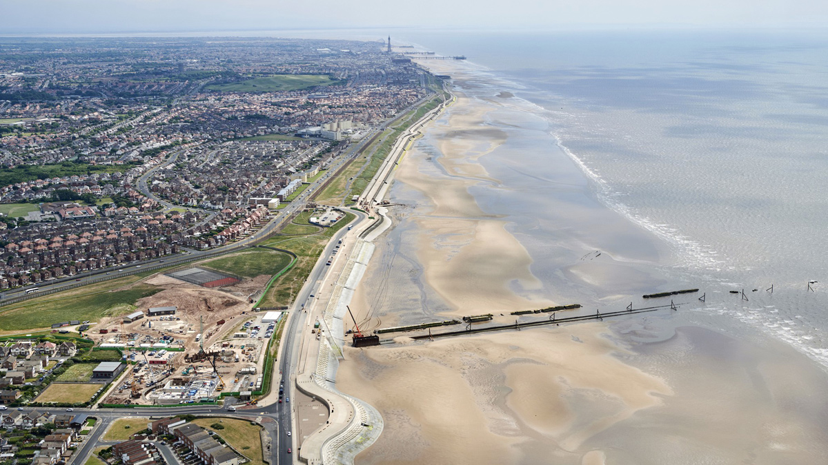
Anchorsholme Park in relation to the Fylde Coast - Courtesy of United Utilities
Anchorsholme Park is located on the coast 4 miles north of Blackpool Tower. The outfall pumping station project is the second of three phases contributing to improving bathing waters on the Fylde coast. The objective of the overall scheme is to complete the AMP5 obligations on the Fylde Coast of the ‘moving towards three spills per bathing season’ National Environment Programme (NEP) driver. The first phase to construct a 12,000m3 stormwater storage facility within the park was successfully completed in 2016. The third phase to construct the 3.7km long sea outfall was completed in late 2018.
The second phase is the outfall pumping station, which is the focus of this article.
Project scope
The project was awarded in October 2016 as a design and build to C2V+ (a joint venture between CH2M (now Jacobs) and VolkerStevin) and their supply chain partners Ward & Burke Construction Ltd, Gallaway Construction and Eric Wright Civil Engineering. Works comprised:
- A below ground 11.84m3/s stormwater pumping station 32m internal diameter x 20m deep incorporating 1500m3 stormwater storage, 6mm escalator screens, washwater and screenings return systems serving a population equivalent of 192,000.
- Above ground main control building sized at 35m x 18.5m and incorporating a 6.6kV HV substation, transformer, 3.3kV variable speed drives (VSDs) and LV electrical control equipment, odour control, ventilation, welfare facilities and integral pump hall sized at 16m x 16m.
- Connection to an existing 6m deep 2.6m x 2.6m (internal) concrete culvert sewer within Anchorsholme Lane constructed in the 1930s, together with a weir chamber connecting the box culvert to the new pumping station.
- Discharge pipework including pressurised structures, a manifold chamber 18.2m x 2.3m x 5.5m deep and a pressure chamber 11m diameter x 12m deep to connect to the new outfall.
- 102m of 2.5m ID tunnel sewer under the promenade and sea defence from pressure chamber to a temporary cofferdam on the foreshore (connection to the new 3.7km outfall in phase 3).
- Pumped pipework to return flows back to the network.
- Improvements to the public park included landscaping and drainage, a café, a bowling club and maintenance building, roads and decorative hard standing, a playground and MUGA.
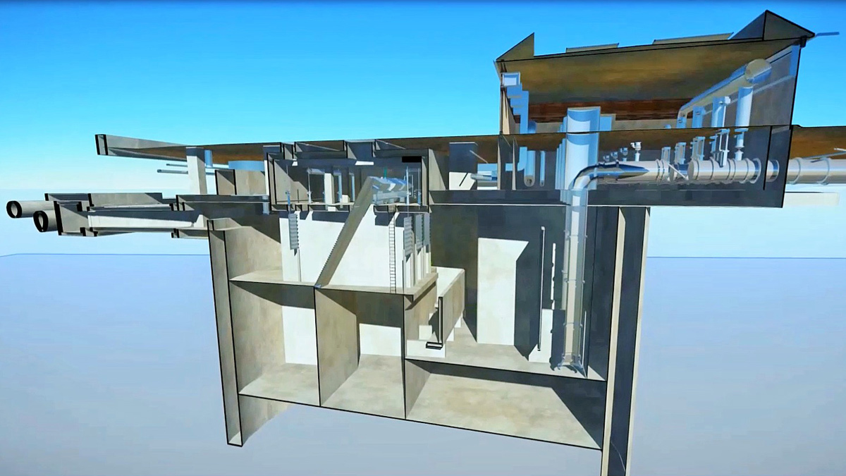
3D section of new pumping station through hydraulic profile – Courtesy of United Utilities
Hydraulic design
The pumping station design capacity of 11.84m3/s @ 21m head was determined in consultation with United Utilities through a Joint Probability Analysis of sewer flows and tides. Key hydraulic considerations in the design included:
- The outfall will naturally empty down to the level of the lowest tide. It is essential that this air is removed in a controlled manner before pipe full capacity is discharged by the pumps to avoid impacts on flow capacity, pressure transients and potential damage to the outfall.
- A sophisticated pump control philosophy adopting sequential start-up of the pumps with a time delay was adopted to mitigate the priming risk. The control philosophy was developed balancing the competing demands of priming the outfall with maintaining the level of service in the upstream sewer network.
- A surge protection system was developed incorporating a pressure chamber to limit peak pressure transients to <2 barg, which ensured the structure was declassified from the Pressure Vessel Regulations.
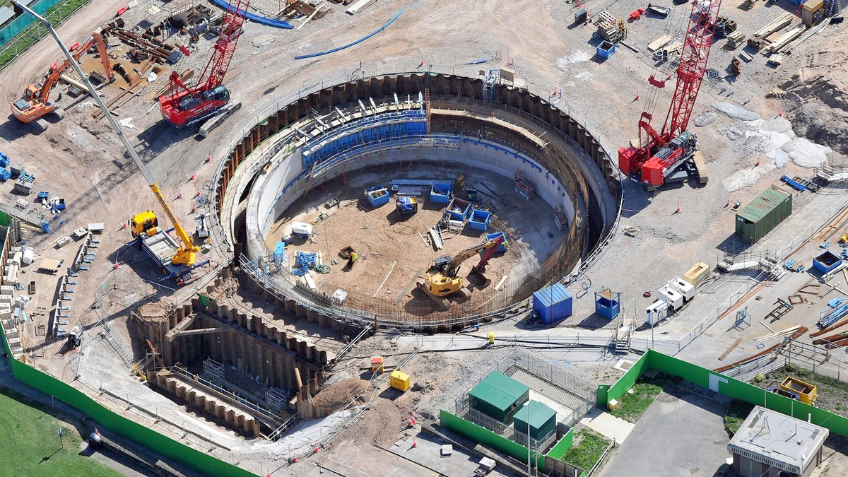
Aerial image of 32m diameter x 20m deep shaft for pumping station construction – Courtesy of United Utilities
- CFD Analysis suggested a low to medium sediment load would be transported through the pumping station to the outfall. In particular the sewer system characteristics would tend to retain a significant proportion of the grit load within the sewer culvert.
- Physical hydraulic 1:7 scale modelling of the pumping station was undertaken to optimise the geometrical design of the pumping station. The modelling endorsed the proposed operating levels and control regime and provided close correlation to the CFD modelling in relation to sedimentation risks.
- One pump discharge was predicted to be sufficient for achieving self-cleansing conditions for the anticipated sediment load in the outfall pipe.
Value challenge
Extensive value engineering at the project outset was required to meet United Utilities budgetary constraints. TOTEX savings have been realised by:
- Adopting a joint probability and risk management approach to specifying the mechanical equipment. This removed the requirement for grit settlement and standby facilities for the storm discharge pumps, escalator screens and odour control fans, which greatly reduced the pumping station footprint.
- This in turn allowed adoption of the same cast in situ caisson approach successfully developed on phase 1, which enabled reuse of the phase 1 formwork. This methodology offered flexibility in reacting to changing ground conditions, less environmental risk and shorter Programme compared to diaphragm wall construction, which was otherwise being considered for the larger footprint station.
- Adopting the same design concept to connect to the existing sewer culvert proven on phase 1 which involved building a load bearing weir/connection chamber around the sewer.
- Optimising the pressure management system to limit pressure transients reducing maintenance and inspection requirements.
- Rationalising the electrical control system through selection of 6.6kV to 3.3kV high efficiency VSD’s and 3.3kV storm discharge pumps to design out two number 3.3MVA transformers.
Geology at pumping station
Groundwater observations made during borehole investigation recorded high confined pressures in the Glacial Sand and Gravel at depth. ‘Blowing sand’ was noted in boreholes at depths of 43m to 45m below ground level. The strata/depth (m below ground level) finding were:
- Blown Sand: 0m to 2m
- Upper Glacial: Till 2m to 8m
- Middle Sand: 8m to 19m
- Lower Glacial Till: 19m to 30m
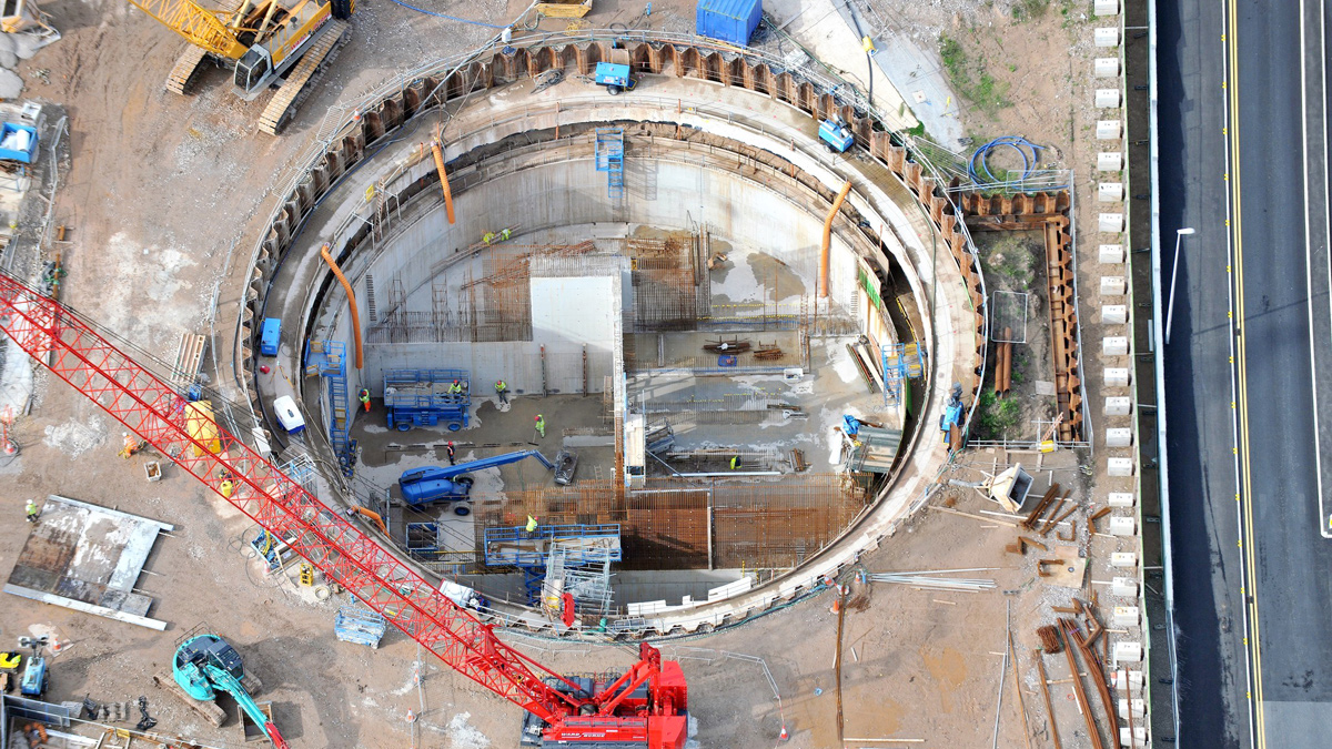
Pumping station internal segregation construction for the wet well, screen returns and screen room – Courtesy of United Utilities
Pumping station below groundworks
The shaft was constructed in two phases. The initial phase comprised installing a temporary sheet piled cofferdam and excavation to 10m depth. Then installation of 3 (No.) lines of reinforced concrete ring beams at 3m, 7m and 10m depth, to act primarily as TW support to the cofferdam, but also as guide collars to control shaft sinking.
Following from lessons learnt on Phase 1 shaft, the ground along the sheet piled location was pre-augered close to depth to aid driving and minimise impact of noise and vibration.
The second phase involved installation of a cutting shoe and construction of the 1m thick caisson wall in 4m lifts using an innovative travelling wall shutter. Once the wall height reached ground level the shaft sinking commenced by excavation within the caisson at the cutting shoe. Verticality during shaft sinking was controlled and monitored using pairs of tiltmeters (vertical and horizontal) on the shaft wall at third points to ensure the sinking was in a controlled manner.
Depressurisation wells surrounding the tank were incorporated in the temporary works design for shaft construction below 8m depth to mitigate risk of base heave from sub-artesian pressure within the middle sand layer. A drainage layer and 3 (No.) pressure relief wells were incorporated into the base design to relieve pressure in the temporary condition. This methodology proved to be very effective during shaft construction.
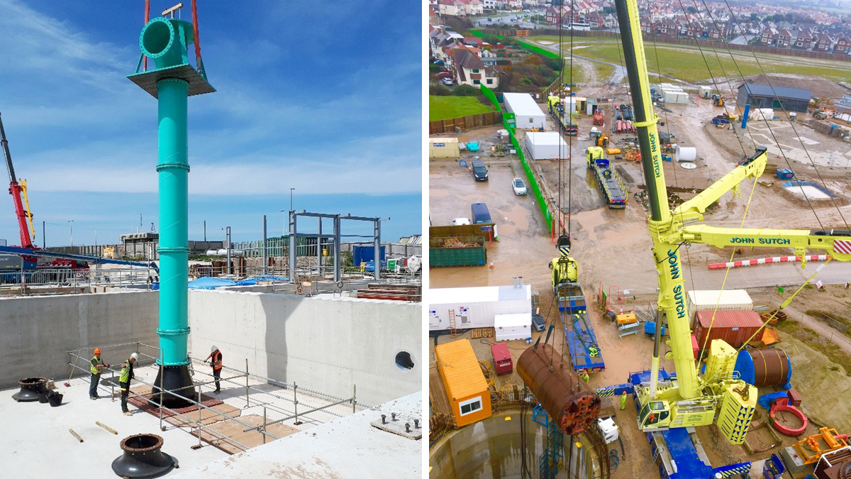
(left) Installation of suspended bowl pumps into the wet well and (right) Installation of TBM into launch pit which has now become the permanent pressure chamber – Courtesy of United Utilities
The shaft itself was specifically designed into separate sections for the various parts of the subterranean screen lanes, dry well, pump well, screening returns and lower sump. Internal segregation wall construction was a combination of precast and in situ RC to fit into the footprint of the circular shaft.
Unused cells were predominantly backfilled and compacted with recycled material from the original shaft excavation. This helped with the 95% achieved diversion of excavated materials to landfill.
The pump hall basement cantilevers off the pumping station shaft and is connected by post-tensioning the deep walls back into the shaft internal structure.
The roof structure was designed for heavy vehicular loading. It comprised precast reinforced concrete beam and planks and topped off with a structural screed. The extensive openings providing access to the shaft and installed equipment make the roof design challenging.
Pumping station above groundworks
The control building housing the control equipment comprises a steel framed portal structure with blockwork external and internal division walls. Externally, all of the building structures are clad at the lower level in a high quality adhered stone veneer with a high-pressure timber laminate façade upper level.
The 11.84m3/s 850kW vertically suspended bowl pumps operate on a duty/assist/assist/assist basis. The pumps and associated control valves are designed to be lifted out the pump hall through access openings in the roof of the building.
One of the most challenging aspects of the project has been programming the construction of the above groundworks within a very constrained footprint.
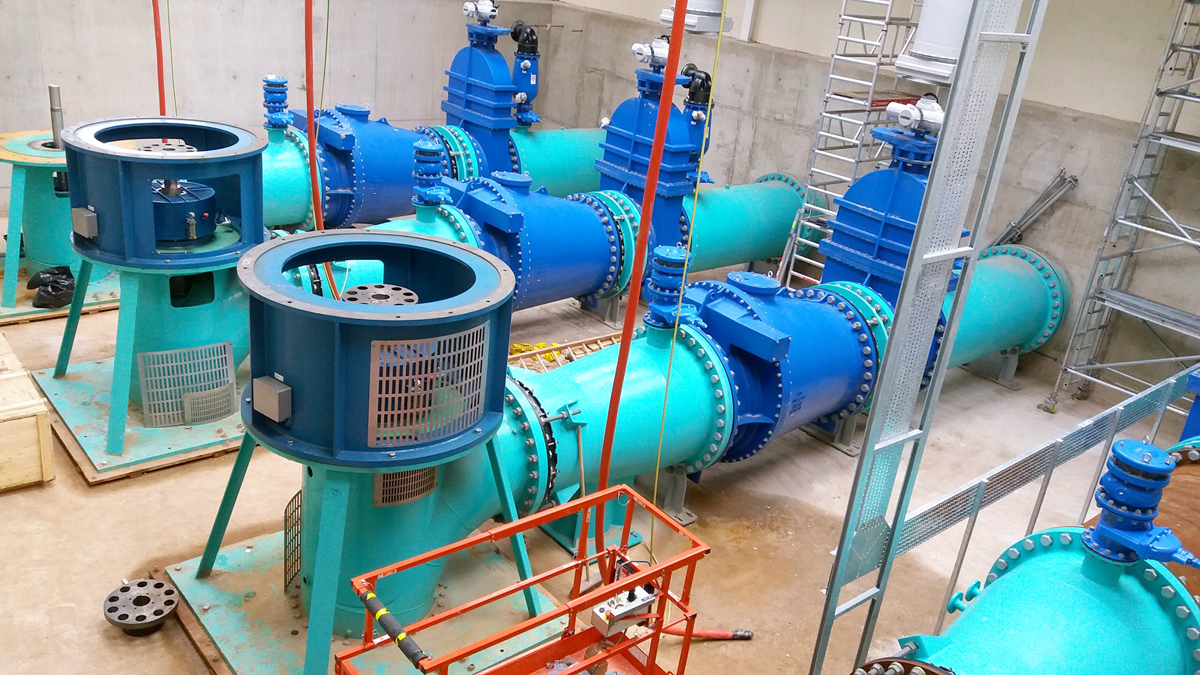
Suspended bowl pumps installed with individual 1.2m dia pipework that heads to new manifold structure – Courtesy of United Utilities
Once the building substructure was completed sufficiently, sections were released for the sub-contractor M&E Installation. This required close collaborative working with multiple installations running concurrently and sharing craneage. This was managed by weekly collaborative planning meetings to ensure that all sub-contractors work was planned effectively and that site H&S standards were met.
At a peak there were 8 subcontractors working within the building footprint at any one time. Key programme aspects included:
- Installing the twin 4.5m diameter x 4m high odour filters and storm discharge pumps and pipework up to 1.2m diameter in basement areas prior to erection of steelwork.
- Installation of the odour control ductwork up to 1.3m diameter and ventilation pipework up to 1.25m diameter immediately after installation of steelwork.
- Installing access metalwork to meet supply chain access requirements.
- Coordinating control equipment and electrical cabling and mechanical pipework installation.MCC build and installation with over 16,000 lnm of HV/LV cabling works laid.
- Commissioning testing.
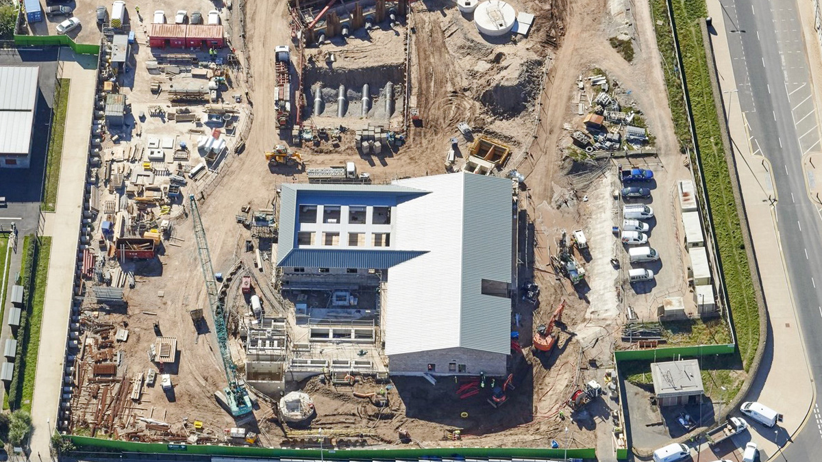
New facility building, individual 1.2m dia pipework to the manifold, new RC manifold and pressure chamber to the LSO – Courtesy of United Utilities
Weir chamber
Storm flows in the network initially fill the available storage including the phase one 12,000m3 storage tank before entering the new pumping station. The pumping station connects to the existing 1930s sewer culvert via two new 5.2m x 1.5m x 11m long precast box culverts and flow into the pumping station is controlled via a fixed weir.
The same concept that was successfully used on the phase 1 works was adopted, where the opening to the culvert was undertaken early on and then temporary steelwork bulkheads were installed to isolate the works until ready to receive flows.
The new connection structure straddles the existing culvert and carries all external loads, self-weight and the existing culvert, the culvert being retained as little more than a permanent liner avoiding the risks associated with residual structural integrity and life expectancy of the existing asset once openings were formed.
Tunnel works
The tunnel was constructed using a Herrenknecht 2500 AVN slurry faced tunnel boring machine (TBM) adapted with a DN2500mm concrete jacking pipe. Ward and Burke selected the TBM to offer the optimum construction risk profile in dealing with water bearing sands and gravels and boulder clays.
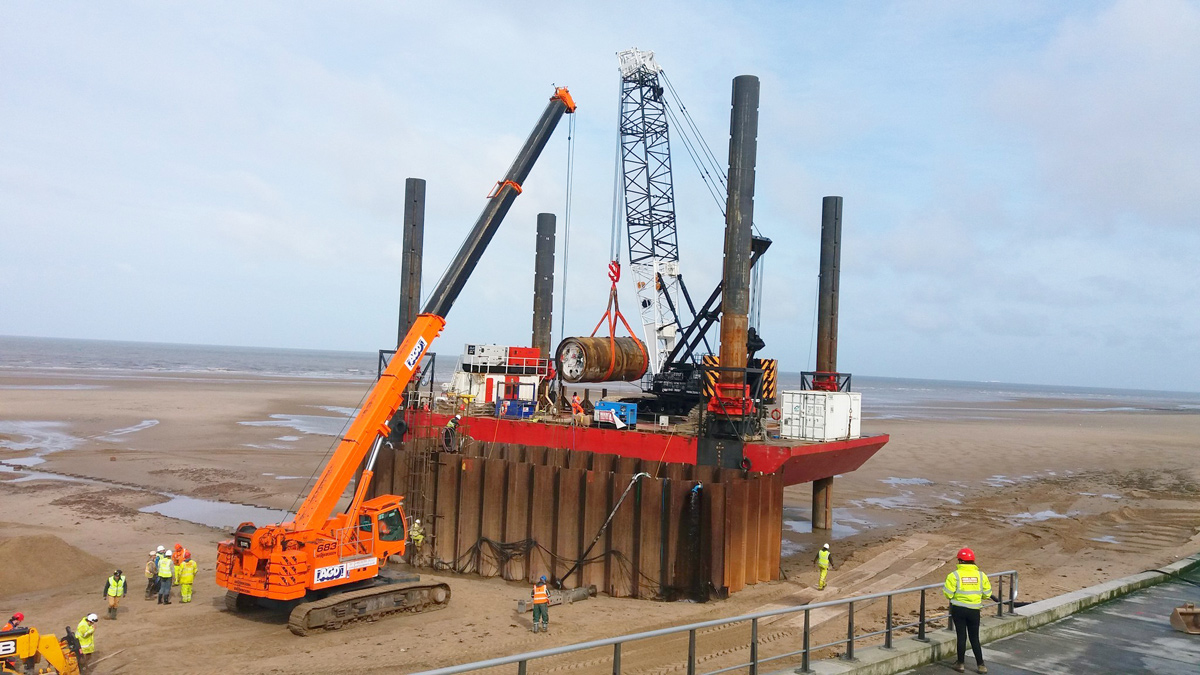
Removal of TBM from temporary marine cofferdam onto the jack-up barge – Courtesy of United Utilities
The tunnel passes beneath the Anchorsholme coast protection structure which comprises a revetment slope (lower slope revetment and upper slope wave breakers), wave wall, raised promenade, rear flood wall and the highway (Princes Way). At the point that the tunnel crosses the toe of the revetment there is a shallow (approximately 3.5m deep) sheet piled wall that is designed to provide scour protection to the revetment.
The profile of the long sea outfall required the tunnel to pass <1m below the capping beam and through the sheet piled toe wall. A new permanent sheet piled cofferdam with capping slab was constructed immediately in front of the crossing point to provide long term scour protection. Following detailed discussions with Blackpool Borough Council and the coastal designers, the existing capping beam was broken out in stages over a 9m length and the revetment propped off the capping slab.
The existing sheet piled scour wall was then removed over a 5m length and a new reinforced concrete capping beam installed.
A temporary reception cofferdam was constructed within the tidal foreshore for the TBM extraction by jack up barge and connection to the new long sea outfall. The design and construction of the cofferdam faced several challenges, including extremely difficult ground conditions, the forces enacted by the tidal influence and winter weather bringing several large storms.
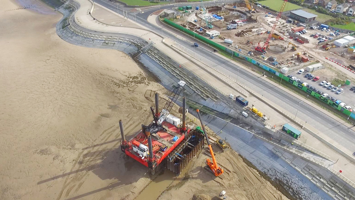
Aerial view of temporary marine cofferdam, jack-up barge, promenade and launch pit highlighting tunnelling route – Courtesy of UU
A detailed RAMS and monitoring array was agreed with the tunnelling subcontractor including establishing trigger levels based on anticipated ground conditions, cover and control parameters.
During the tunnel drive a boulder obstruction was encountered, which slowed tunnel progress and manifested as a brief increase in face pressure. Shortly afterwards, one of the monitoring arrays noted a settlement trend which when investigated was identified as a void at ground level at the edge of the carriageway.
Traffic restrictions were immediately implemented and the void backfilled with concrete. Subsequent monitoring over several months showed no further movement or distress to the carriageway.
The project followed the Joint Code of Practice for Risk Management of Tunnel Works in the UK (JCoP). A register was adopted to track and evidence compliance with the code recommendations. This proved a useful tool to assist the client in demonstrating to the tunnel insurers how risk was being managed.
Community engagement
Considerable stakeholder management has been done to keep customers impacted by the works informed of the construction activities, particularly the properties directly impacted by the connection works. This has included:
3D video and virtual reality models created from 3D BIM models to assist visualisation.
- Public awareness campaign, posters, articles and letter drops.
- A customer centre was operated weekly on site for members of the public to get update information about the scheme.
- Open days with guided tours to allow stakeholders and residents to see actual progress and understand the physical works.
- Regular communication with local residents.
- Support to local community groups such as the Bowling Club/RNLI and Love my Beach.
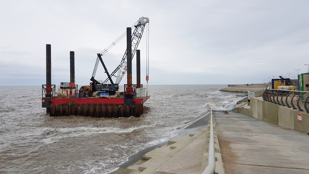
Jack-up barge and temporary marine cofferdam during high tide – Courtesy of United Utilities
This has mitigated risk of trespass on the construction site and the associated health & safety risk to the public, particularly children and has drawn praise from residents, with one hundred WOW nominations received throughout the project.
Throughout the project UU have continually liaised with Blackpool Borough Council, to ensure that planning was granted for the works and conditions have been met to ensure a smooth handover of the final landscaping.
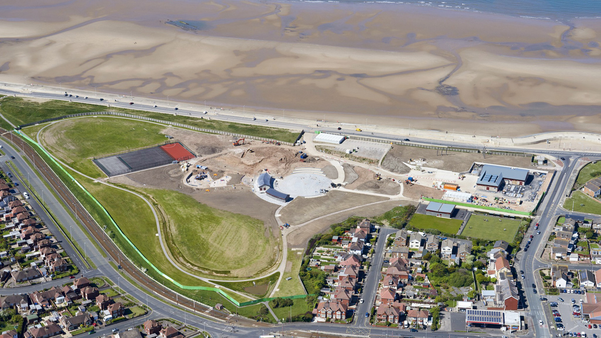
Anchorsholme Park development nearing completion with redeveloped park, new MUGA, new café, new bowling club, new amphitheatre, and new pumping station (May 2019) – Courtesy of United Utilities
Summary
Through working in close collaboration, the project team has overcome issues with existing infrastructure and delivered an innovative construction solution forecast to be completed in line with National Environmental Programme.