
Anchorsholme Park Storage (2016)
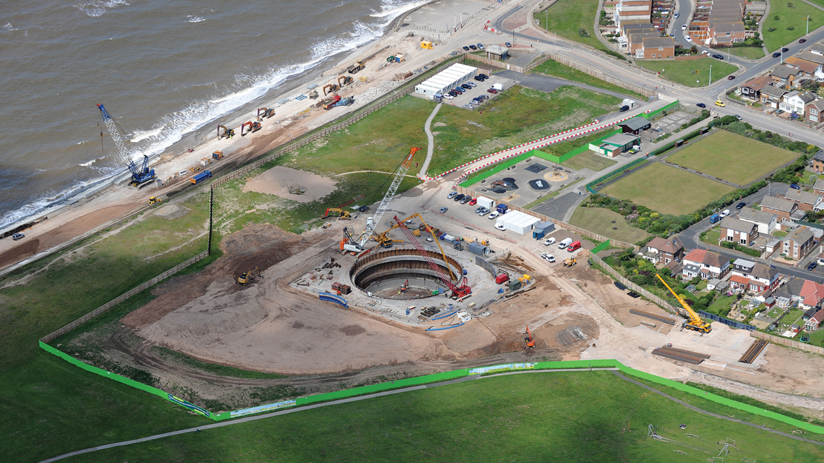
Site layout - Courtesy of C2V+
Anchorsholme Park is located on the coast 4 miles north of Blackpool Tower. The storage project is the first of two phases contributing to improving bathing waters on the Fylde coast. The objective of the initial phase is to complete the AMP5 obligations on the Fylde Coast of the “moving towards three spills per bathing season” National Environment Programme (NEP) driver. During periods of heavy rainfall the 12,000m3 storage facility will retain stormwater which otherwise would be discharged into the bathing waters through a consented outfall.
Project scope
The project was awarded in February 2015 as a design and build to C2V+ (a joint venture between CH2M and Volker Stevin) and its supply chain partners Ward & Burke and Eric Wright and comprised:
- 12,000m3 stormwater detention tank 30m internal diameter x 25m deep incorporating twin vortex drop shafts, pumping equipment and tank cleaning systems.
- Connection to an existing 7m deep 2.6m x 2.6m (internal) concrete culvert sewer constructed in the 1930s, together with a weir chamber connecting the box culvert to the new tunnel sewer.
- 145m of 1.8m ID tunnel sewer from the weir chamber to the detention tank.
- Pumped and gravity pipework to return flows back to the network.
Hydraulic design
Flow into the tank is controlled by the new weir and conveyed to the tank in a 1.8m DN tunnel sewer. The tank invert is approximately 15m below the incoming 1.8m DN tunnel sewer. Twin 1.6m ID vortex drop pipes are provided to convey the effluent to tank base level to reduce inflow velocities and disperse energy.
The vortex drop and scroll design allows excess flow to overspill the scroll structure, with the lower benching finished with steel fibre reinforcement to provide a hard wearing, durable surface, capable of dealing with the energy from the falling water.
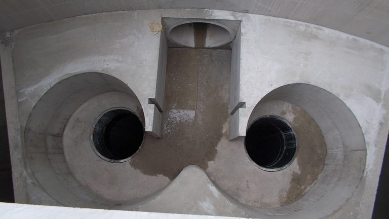
Vortex – Courtesy of C2V+
To mitigate siltation risk the storage tank has a dual vacuum flushing system comprising a central and a peripheral column. The central column also acts as a load bearing member supporting the roof structure.
Variable speed drives were adopted to maintain an even pumped flow rate for drain down of the tank. Lessons learned by United Utilities (UU) Operations from other storage tanks in the area were incorporated into the design including configuration of the discharge pump inlets, inclusion of aeration and peripheral flushing systems and higher than normal minimal velocities in the return pipework.
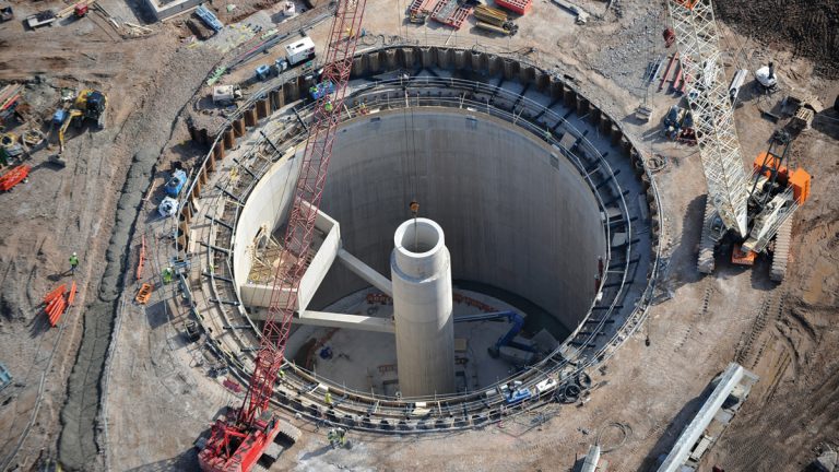
VacFlush – Courtesy of C2V+
Geology at tank
Groundwater observations made during borehole construction recorded high confined pressures in the Glacial Sand and gravel at depth. ‘Blowing sand’ was noted in boreholes at depths of 43m to 45m below ground level.
Strata: Depth (m below ground level)
- Upper Glacial Till: 0 to 2m
- Middle Sand: 2 to 12m
- Lower Glacial Till: 13m to 43m
- Glacial Sand and Gravel: 43m and below
Detention tank
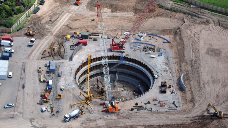
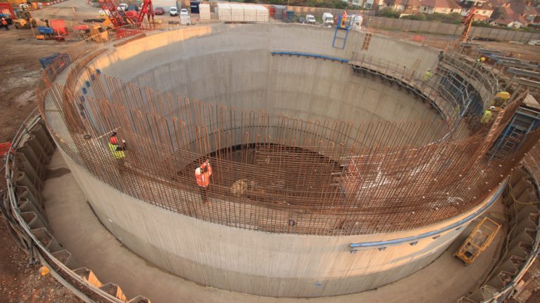
Value engineering at the project outset favoured shaft construction adopting an innovative cast in situ caisson approach developed by sub-contractor Ward & Burke. This methodology offered flexibility in reacting to changing ground conditions, less environmental risk and shorter programme compared to diaphragm wall construction. Secondary benefits include achieving water retaining wall construction without additional treatment, incorporation of shear connections without post drilling, and cost effectiveness in that the temporary works can be incorporated into the permanent works.
The shaft was constructed in two phases. The initial phase comprised installing a temporary sheet piled cofferdam and excavation to 12m depth, installing 3 (No.) lines of reinforced concrete ring beams at 3m, 8m and 12m depth, to act primarily as TW support to the cofferdam but also as guide collars to control shaft sinking. Prior to the installation of the temporary piles the ground along the location was pre-augered close to depth to aid driving and minimise impact of noise and vibration. The upper and lower concrete collars were subsequently incorporated into the permanent works (upper ring beam dowelled to the final wall pour and the lower ring beam attached to the upper via tension columns). This allows for mobilisation of a soil wedge to help resist flotation and lead to a more efficient design.
Cutting shoe installation showing guide beams – Courtesy of C2V+
The second phase involved installing a cutting shoe and constructing the 1.5m thick caisson wall in 4m lifts using an innovative travelling wall shutter. Once the wall height reached ground level the shaft sinking commenced by excavation within the caisson at the cutting shoe. Verticality during shaft sinking was monitored using pairs of tiltmeters (vertical and horizontal) on the shaft wall at third points.
Depressurisation wells surrounding the tank were incorporated in the temporary works design for shaft construction below 16m depth to mitigate risk of base heave from sub-artesian pressure from constrained sands and gravels layers just below base excavation. A drainage layer and 3 (No.) pressure relief wells were incorporated into the base design to relieve pressure in the temporary condition. This methodology proved to be very effective and shaft construction was delivered on programme.
Travelling wall shutter and steel fixing – Courtesy of C2V+
A soft eye was included in the shaft wall to receive the incoming 1,800mm sewer. Box outs were cast into the wall for support steelwork for the vortex scroll box and for shear connectors to the base, avoiding the need for post drilling.
The base was cast in four pours, two for the 5m deep structural base and two for the 1.7m deep benching. Careful consideration was paid to the concrete specification to account for heat generation and to achieve the required durability criteria. Four concrete suppliers were used to mitigate supply risks.
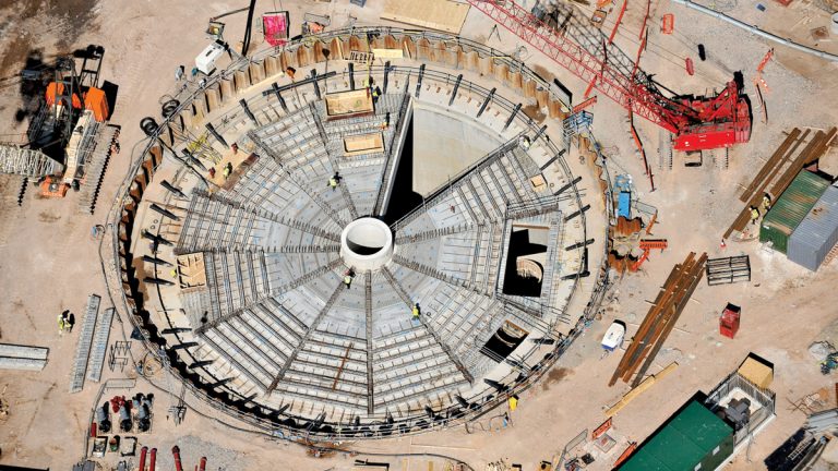
Precast roof install – Courtesy of C2V+
The roof structure was designed for heavy vehicular loading and up to 5m soil backfill. It comprised 12 (No.) precast reinforced concrete beams supported on the central flushing column and box-outs within the shaft wall. The beams were overlain with precast planks and topped off with a structural screed; it is penetrated by 14 (No.) openings up to 6m x 2m providing access to the shaft and installed equipment making the roof design challenging.
Weir chamber
One of the most significant health, safety & environmental risks on this project was the requirement to form a 6m long weir connection to the buried box culvert sewer. The sewer originated from the 1930s and no records of condition were available. The culvert could not be temporarily isolated and the flows were too great for over-pumping to be considered.
The tender concept involved building a weir/connection chamber around the sewer and constructing the tunnel through the park to connect to the new buried 12,000m3 detention tank. The new weir chamber would straddle the existing culvert and carry all external loads, self-weight and the existing culvert, the culvert being retained as little more than a permanent liner avoiding the risks associated with residual structural integrity and life expectancy of the existing asset once openings were formed.
Weir chamber and culvert including – tunnel drive – Courtesy of C2V+
Site investigations led to the discovery that the culvert was located within private gardens and close to property. A laser and photographic survey was undertaken to confirm the exact line, level and visual condition of the culvert. An optioneering study in close collaboration between UU and C2V+ determined the most suitable solution. A robust and transparent audit trail was delivered to defend against potential third party challenge. Health & safety in construction, operation and maintenance, and management of the impact upon private gardens was important criteria adopted as part of the option assessment process.
The agreed solution was to relocate the point of connection to within the footprint of two private gardens within 12m of the property. This element of the works was redesigned as follows:
The weir/connection chamber was split into two. The larger weir chamber element was moved out into the public park with only a small footprint connection chamber required within the private gardens. The weir chamber contains the isolation penstock to the detention tank so moving this into the park removes the need to enter private land for maintenance of the penstock.
- The weir chamber also doubled as a temporary launch pit for the tunnelling works; so keeping this in the park kept the tunnelling works as far away from private property as could practicably be achieved.
- The connection detail was redesigned to minimise the size of openings to be formed in the existing culvert.
- A temporary steelwork bulkhead was developed which could quickly be fitted to the formed opening to retain storm flows that would otherwise risk flooding to excavations.
- Precast box culverts were incorporated into the design to connect between the culvert and the weir chamber. This minimised working time within the private gardens.
- Permanent access points were designed out of the culvert but have been provided in the weir chamber structure in the park. This removes the need for operational access to private gardens.
- The pumped return from the detention tank has been incorporated within the weir chamber on the ‘wet’ side of the weir to provide a flushing effect within the culverts to mitigate sedimentation risks.
- A silent pressed piling method was adopted for piling the temporary works to mitigate construction induced vibration and noise nuisance due to close proximity to the adjacent residential properties.
A settlement monitoring plan was prepared and pre-construction condition surveys undertaken which were agreed with property owners. Work in the garden was carried out in the winter months and these were recreated and handed back to owners in late spring.
Tunnel works
The tunnel was constructed using a Herrenknecht 1600 AVN slurry faced tunnel boring machine (TBM) with a DN1,800mm concrete jacking pipe. The TBM selection was considered to offer the optimum construction risk profile in dealing with water bearing sands and gravels and boulder clays.
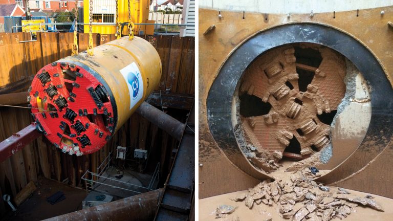
(left) Mobilisation of TBM and (right) TBM break through – Courtesy of C2V+
Settlement was assessed for impact on nearby assets and property and was considered to be negligible (<8mm above pipe crown for volume loss up to 1%). Nevertheless a monitoring regime was implemented to understand the soil response to construction close to infrastructure and property local to the works. The monitoring consisted of surveying and inclinometers near to adjacent structures. Pre and post condition surveys were also undertaken for nearby property, with the pre-construction condition agreed with homeowners prior to commencement of the works.
The project followed the Joint Code of Practice for Risk Management of Tunnel Works in the UK (JCoP). A register was adopted to track and evidence compliance with the code recommendations. This proved a useful tool to assist the client in demonstrating to the tunnel insurers how risk was being managed.
Community engagement
Considerable stakeholder management has been done to keep customers impacted by the works informed of the construction activities, particularly the properties directly impacted by the connection works. This has included:
- Public awareness campaign, posters, articles and letter drops.
- Open days with guided tours to allow residents to see actual progress and understand the physical works.
- A weekly public drop in centre on site.
- Regular communication with local residents.
- Support to local community groups such as the Bowling Club.
This has mitigated risk of trespass on the construction site and the associated health & safety risk to the public, particularly children and has drawn praise from residents, with over twenty-one WOW awards received throughout the project.
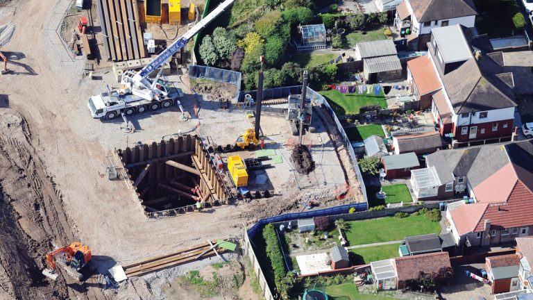
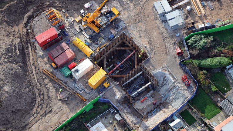
Aerial shot of culvert works – Courtesy of C2V+
Summary
Through working in close collaboration the project team has overcome issues with existing infrastructure and delivered an innovative construction solution on programme, on budget and with positive customer feedback.
Editors Note
Following on from this paper, United Utilities provided case studies on the subsequent phases of the Anchorsholme Project: