
Minworth STW – Thermal Hydrolysis Plant (2018)
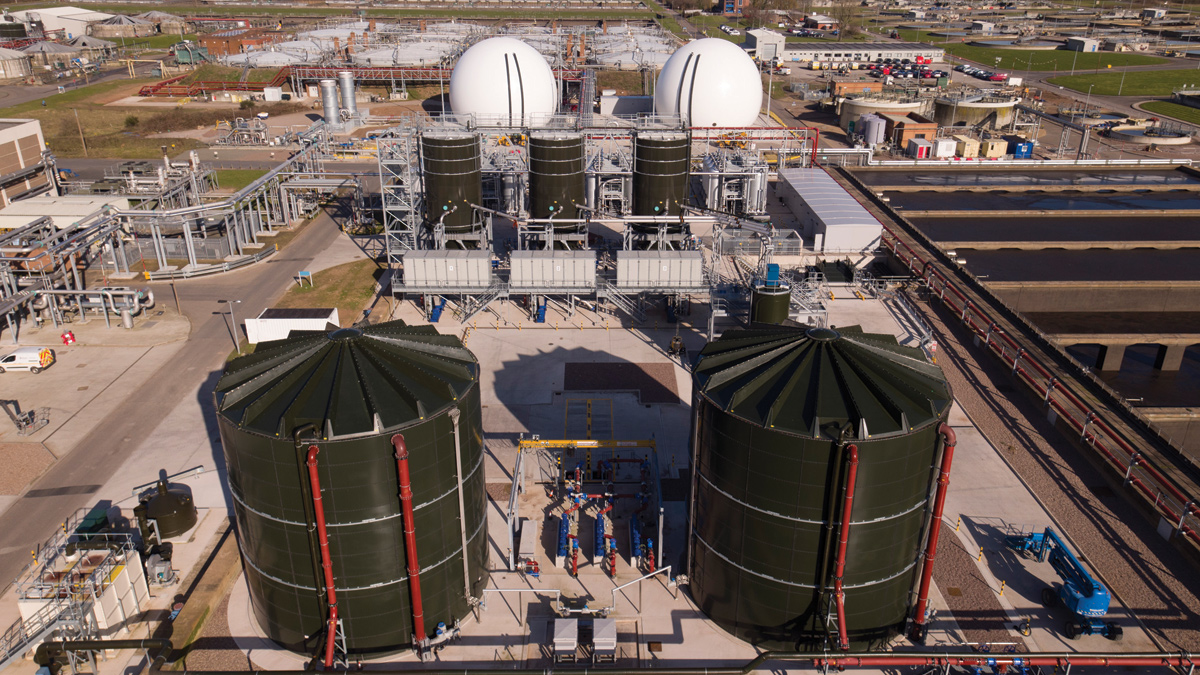
THP general arrangement - Courtesy of MWH Treatment
Minworth STW is Severn Trent’s largest sewage treatment works and serves a population equivalent of 1.75 million from Birmingham with full flow to treatment of 1,070Ml/d. The works treats sludge arising from a population equivalent of 2.3 million which is made up of indigenous sludge plus imported sludge from the nearby Coleshill STW and various works in south Staffordshire and North Warwickshire. As part of their PR14 submission to OFWAT, Severn Trent has made commitment to cut their carbon footprint by 10% through AMP6 and to produce an enhanced product for 25% of all of their biosolids. In order to achieve these drivers a thermal hydrolysis plant (THP) has been constructed at Minworth designed to treat peak 89,060 tDS/year and average 71,175 tDS/year. The THP has been designed and constructed by Severn Trent’s framework contractor Stantec Treatment in collaboration with key technology providers.
Primary sludge screens
Primary sludge is screened with 6 (No.) Huber Technology SP4 Strainpresses designed for ease of maintenance with service wheels to allow the body to be split for clear access to the auger. The Strainpresses were factory pre-assembled in six modules complete with the electro-pneumatic local control panels which were fully cabled and tested. They were installed on an elevated platform in just 1 week saving site time and reducing the risks associated with working at height. The screenings capture rate is impressive and will protect the THP from blockages and excessive wear.
Sludge feed
Liquid imports, indigenous thickened surplus activated sludge (SAS) and screened primary sludges are blended in existing reception tanks then transferred utilising the existing ram pumps to new buffer tanks with air mixing. New DI pump delivery manifolds were installed in the digester pump station with twin 300mm diameter feed pipelines running 400m to the new plant.
A key design consideration was to ensure a consistent feedstock so the sludge inventory was monitored to confirm sludge characteristics. The commissioning team worked with STW Operations to verify the primary/SAS ratio of 70:30.
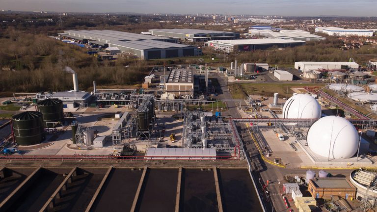
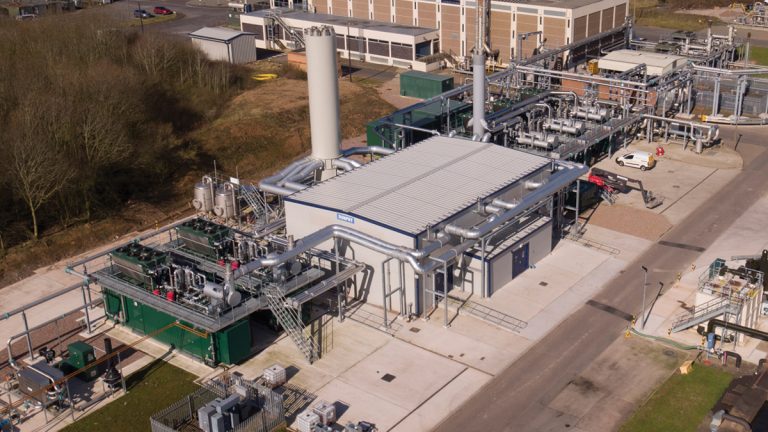
THP constructed on redundant tanks and integrated with existing digester and renewable energy assets – Courtesy of MWH Treatment
Pre-thermal hydrolysis dewatering
3 (No.) Alfa Laval G3-125 centrifuges dewater the sludge to 20-22% dry solids with associated Richard Alan polyelectrolyte dosing plant. These decanters feature innovations to reduce the power consumption, increase capacity and achieve precise control of the differential speed between centrifuge bowl and scroll conveyor using the back-drive controller.
The ‘two touch’ advanced electronic centrifuge controller ensures that a constant quality of cake is produced despite variations in feed. Cake-transfer Mono Pumps with boundary layer injection transfer the sludge to 3 (No.) 300m3 CTM Systems Ltd silos equipped with live screws. Cake is then diluted to 16.5% +/- 1.5% and pumped into the 3 (No.) parallel Cambi THP streams. Interconnecting pipework with manual valves was included to increase operational flexibility and resilience.
Cake import
The cake import bunker receives imported Coleshill cake which is blended with indigenous sludge in the THP feed silos. The delivery of a cake load involves a 30m3 HGV reversing into position and tipping the cake load into the hopper. Imported cake with a thickness of 20-22%DS will be pumped into the cake silos. It is important that the dry solids content of the imported cake remains consistent to ensure that there will be no over or under dilution of the sludge or stratification in the THP feed silos.
Cake bunker and silo feed pipework 316 stainless steel schedule 10 PN25 – Courtesy of Stantec Treatment
Thermal hydrolysis process
The THP is capable of treating a maximum of 250tDS/day or an average of 198tDS/day. The Minworth THP consists of 3 (No.) Cambi B6(4) streams, each of which feeds a block of 4 (No.) digesters. Each stream operates independently in three process stages:
- Sludge is fed into the pulper from a dedicated THP feed silo. The sludge is heated to 100°C using recycled steam from the reactors and flash tank.
- Homogenised, pre-heated sludge is then pumped sequentially to each reactor, for batch treatment. Sludge is heated by live steam injected directly via ‘sparge’ pipes. The sludge is heated to 165°C, >6 barg pressure, and held for 30 minutes for hydrolysis to take place and ensure it is pasteurised. Cycle time can be reduced to 22 minutes to increase throughput.
- The sludge is blown down to the flash tank using the pressure in the reactor. The flash tank operates at ambient pressure, so the sludge experiences a sudden de-pressurisation which ruptures the cell walls, ensuring complete pathogen kill and maximising the digestibility of the sludge.
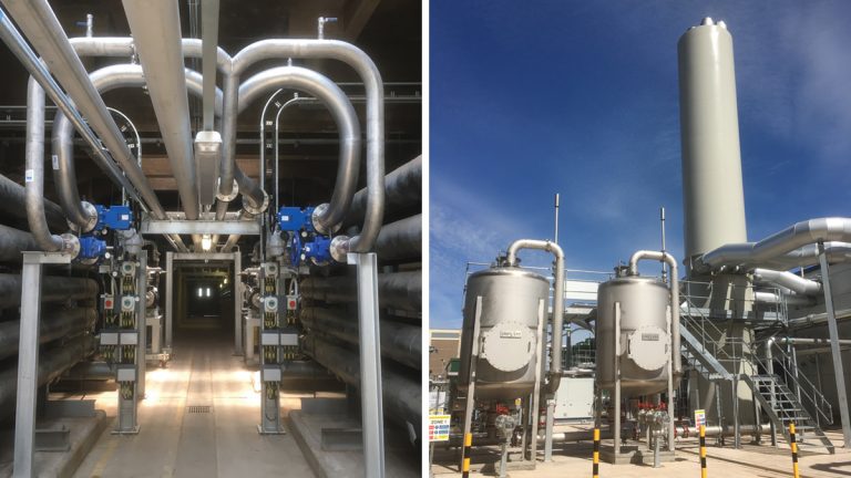
Digester recirculation system
12 (No.) digester recirculation pumps are located within the existing digester galleries. Each pumps from the digester and combines with its digester pair via a recirculation main, through the heat exchangers, where hydrolysed sludge is blended at a 1:3 ratio and cooled to its target temperature set point (normally 42-44°C) then fed back into the pair of digesters. The flow to each digester is controlled by a modulating plug valve and dedicated flowmeter with a flushing cycle to optimise performance.
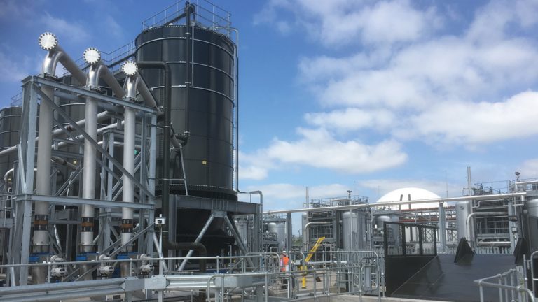
3 (No.) Cambi THP and sludge coolers – Courtesy of MWH Treatment
The recirculation system dilutes the hydrolysed sludge prior to cooling, thereby raising pH of the combined stream and lowering cooler inlet temperature. The pumps are Landia chopper-type equipped with an integral cutting blade to macerate the digester contents and deal with the legacy of high rag content experienced during digester conversion.
The use of Augmented Reality 3D modelling facilitated the detailed design and enabled the optimisation of the installation of numerous pipelines into a busy operational area. The main stainless steel recirculation pipe systems were incorporated into high level rack systems which were prefabricated and factory tested by MEPS as part of the DfMA strategy.
Final effluent and UV
The existing final effluent pumping station (FEPS) feeds the Klampress units in the secondary sludge dewatering plant. Higher duty final effluent pumps have been installed to serve the increased demand from the additional users in the THP area, with new strainers and a UV treatment package to ensure pathogens are not introduced into the post THP processes such that enhanced product status of the cake is compromised.
A set of 3 (No.) 300µm coarse strainers serve the heat exchangers, dewaterer polymer carrier water, washwater, cake import dilution and pre-THP dilution. The Bollfilter auto-backwash strainers feature a Foulex coating to prevent the build-up of biofilm in the strainer elements. A further stage of 50µm fine strainers and Xylem Water Solutions UV treatment system is installed to treat the FE supplied to the THP digester feed pumps, THP process gas cooling and to the secondary sludge dewatering plant for Klampress washwater. Pressure sustaining valves ensure that the FE distribution network remains pressurised at all times.
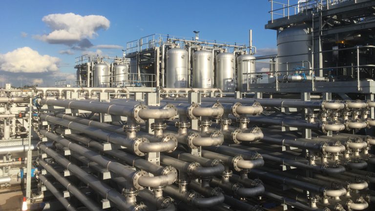
Biogas system and recirculation pipework – Courtesy of MWH Treatment
Anti-surge system
Digester surging was identified as a risk to the project because the uplift in biogas production from THP has more capability to create a sludge density differential. To mitigate this risk, the sludge in the spill columns is continuously aerated using an air lift system to prevent the consolidation of sludge and to date there have been no surging events.
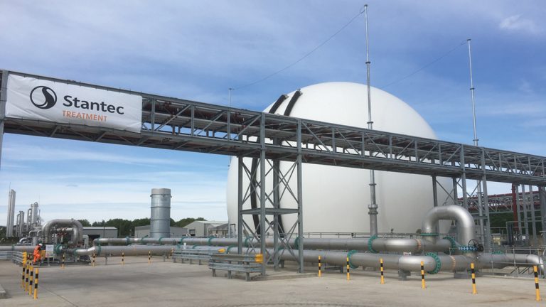
Biogas system
Biogas is collected beneath the floating roofs of the digesters and transferred to the biogas-to-grid (B2G) plant, the 8 (No.) CHP engines and 3 (No.) boilers. In anticipation of a greater biogas yield from the THP, 2 (No.) new biodomes (4000m3 each) will provide additional storage capacity and improved biogas pressure stability. The renewable energy team proactively manage the biogas utilisation to maximise production.
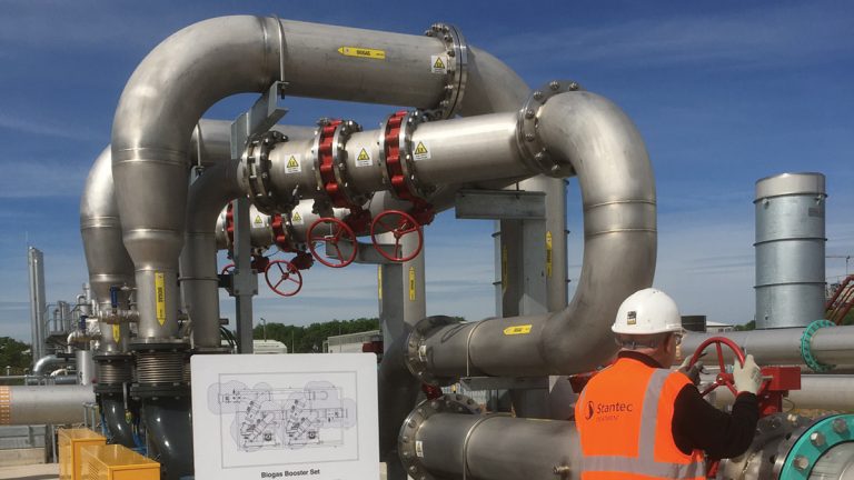
Biogas boosters – Courtesy of MWH Treatment
New biogas boosters will elevate the system pressure downstream of the biodomes to 33mb feeding the CHP’s and steam boiler siloxane plant.
2 (No.) Uniflare waste gas burners (duty/assist) have been provided, capable of burning 1.5 times the anticipated peak gas yield, (7338m3/hr). This safety device has a variable burn rate to prevent a release of biogas through the digester pressure relief valves (Whessoe), in the rare event that more biogas is being produced than utilised.
Boiler system
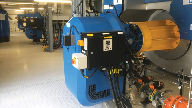
Dunphy Combustion dual fuel burners – Courtesy of MWH Treatment
Steam generation is provided by 3 (No.) 6T/h boilers (duty/assist/hot standby) operating at 11.5 barg and 191.6°C (saturated). The combination steam boilers incorporate a ‘fired side’ which burns biogas or natural gas and a ‘waste heat side’ to recover high-grade heat from the CHP exhausts at 450°C through economisers. In order to maximise energy recovery, 5 (No.) CHP engines are connected to the boilers.
The commissioning procedures for the steam boilers are complex and potentially dangerous; only personnel with BOAS accredited qualifications have the authorisation to operate the boilers. The high integrity control system allows the boilers to be unmanned for 72 hours.
Dunphy won the prestigious Combustion Engineering Association Lord Ezra Award 2017 for the design and manufacture of the high capacity, low NOx, prefabricated, modular energy centre.
Dunphy Boilerhouse and CHPs with high grade waste heat recovery – Courtesy of MWH Treatment
Digester conversion
A critical commissioning activity involves converting the digesters from conventional to hydrolysed sludge. This transition of sludge type alters the biological activity and conditions inside the digesters so must be carefully monitored and controlled to reduce the risk of instability. Hydrolysed sludge is fed into the digesters and existing contents are gradually displaced over a 3-month period.
The rate of ramp-up is adjusted daily in small increments. Each THP stream and its block of 4 (No.) digesters was converted in sequence to manage sludge processing site wide.
The loading of the B/C/D block digesters was phased to maintain digester stability:
- Initially 32-52 tDS/day @ 8-9%DS (conservative due to the pre-start conditions).
- Interim 53-66 tDS/day @ 9%DS design load per THP stream.
- Performance test 80-84tDS/day maximum throughput per THP stream.
The team of experienced THP process commissioning engineers and operators were able to utilise their knowledge to minimise the conversion timeline.
(left) Recirculation pipework in digester gallery and (right) siloxane plant carbon filters – Courtesy of MWH Treatment
Digester health
The health of the digesters determines the sludge feed rate so samples of the digested sludge are taken on a daily basis to monitor for % dry solids content, % volatile solids content, volatile fatty acids, total alkalinity, pH, ammonia content and % methane content in the biogas. The analysis of these parameters is monitored against pre-determined target figures (traffic light system) which is recorded for comparison with the ‘golden measures’ metrics.
If the daily monitoring shows signs of digester volatility then the digester feed is reduced to the ‘sick’ digester until it returns to stable conditions. The feed is diverted to the A-block non-THP digesters, or to the other ‘healthy’ converted digesters. An anti-foam dosing skid was installed to manage foaming events in the digesters which were experienced during conversion.
The effectiveness of the digester mixing influences conversion rates so the existing gas compressors had to be adjusted to run continuously and will be upgraded in the future.
Smart ICA benefits
THP electrical design collaboration with the Severn Trent ICA Standards Group has successfully produced the following innovative approaches:
- First project to commit to the smart ICA ethernet MCC standard developed by the ICA framework suppliers (Total Automation & Power & Cema).
- First commitment to the new ACQ 580 ABB variable speed drives.
- 4 (No.) ME1D approvals for complex package plant panels; approved in 24 hours.
- Back to back ICA section; saving 5m MCC length.
- Use of compact IP54 ABB VSDs on booster package
- Pre-built wiring looms to PLC.
The MCC system integrator Total Automation & Power and electrical installation contractor S&R worked collaboratively to provide a power and control system of the highest quality within tight time constraints.
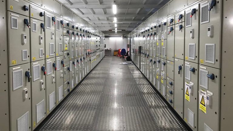
THP motor control centre – Courtesy of MWH Treatment
Pipework strategy
10km of interconnecting pipework were required which was one of the largest programme risks, so the scope was split into five subcontract packages: (i) Alpha Plus Ltd (ii) ABC Stainless Ltd (iii) Franklyn Yates (iv) MEPS and (v) SWT. This engagement with the supply chain unlocked production and installation resources and together with concurrent working enabled us to achieve key dates due to the determination of the mechanical supervision team.
Digital delivery transformation
Extensive application of Stantec’s innovative digital delivery strategy has upskilled the team and generated efficiency. 4D Digital Rehearsals enhanced visualisation and prevented unplanned site activities which was recognised with two synchro awards. BIM has unlocked the power of constructive collaboration and allowed 40 supply chain partners to visually engage, integrate and sequence.
UK manufacturing delivers value
A supply chain with proven performance on THP to ensure resilience has been utilised. Design for Manufacturing and Assembly (DfMA) on 85% of equipment has saved time, improved quality and reduced H&S risks. Key process equipment was manufactured in the UK which will ensure that STW get operational support during the plant life.
Summary
Minworth THP project has been delivered ahead of schedule achieving an early completion bonus which is testament to the high performing collaborative Severn Trent and Stantec team. The attention to detail and lessons learnt from other schemes has delivered a fully integrated design based on operational experience. The integration of the new assets with the existing process units has been extremely complex but the interface manager has excelled in the planning and coordination of the works with the Operations & Maintenance teams to ensure a smooth transition with minimal disruption.
Geese inspect the THP! – Courtesy of MWH Treatment
The site management team has demonstrated strong leadership to achieve a world class safety performance with zero accidents and Considerate Constructors Gold Award 2018. Process commissioning has been well executed and STW are realising the benefits of the advanced digestion upgrade with increased biogas and improved dewaterability of hydrolysed sludge. Performance testing is ongoing with completion forecast for November 2018.