
Crankley Point Terminal Pumping Station (2019)
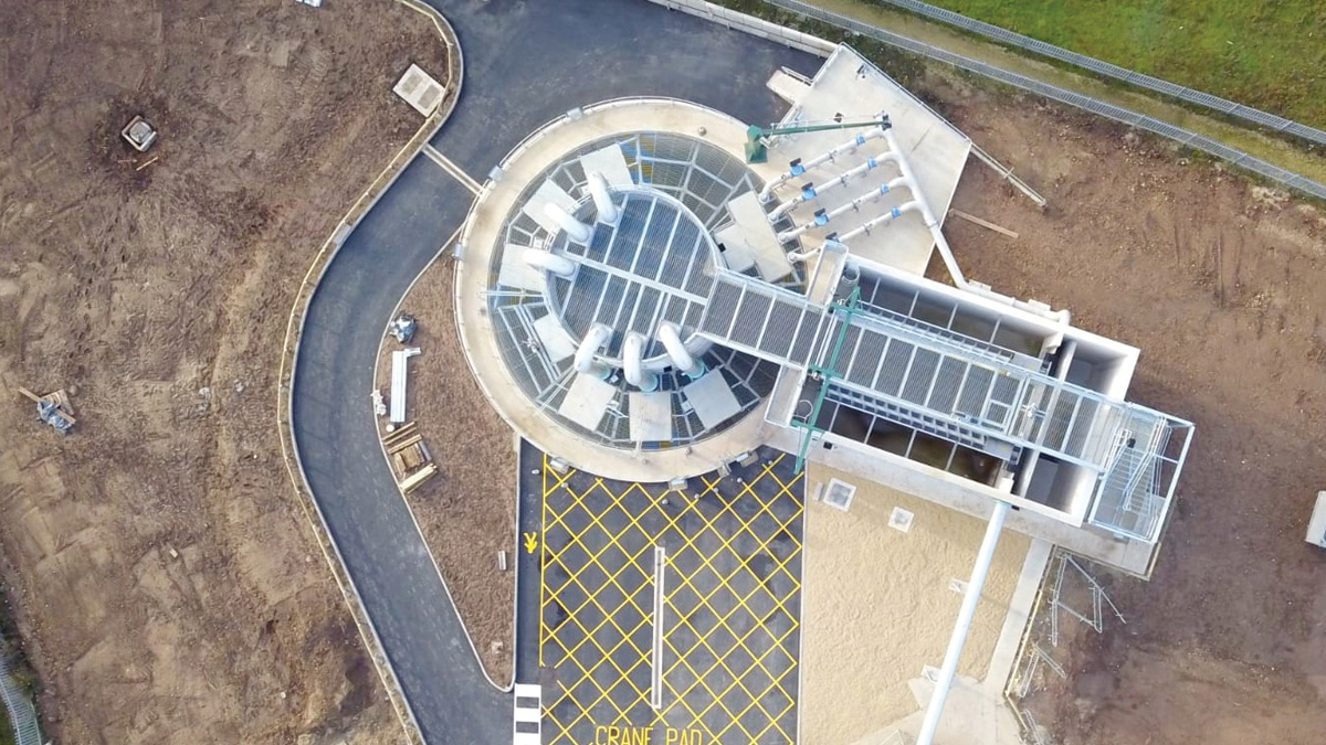
Completed terminal pumping station and screening chamber - Courtesy of nmcn PLC (now Galliford Try)
Crankley Point Sewage Treatment Works (STW) is a Severn Trent asset serving Newark-on-Trent, a town in Nottinghamshire with a population of just under 30,000. As part of the £60 million Newark Waste and Water Improvement Project, a new terminal pumping station (TPS) and screening chamber (SC) with outfall to the River Trent was required to lift flows from a 2.1m diameter, 15m deep sewer, which would become the main inlet to the works. Investment in the Newark sewerage system was driven by a widespread sewer flooding problem throughout the town, affecting almost 400 homes and businesses. An additional benefit being provided by the project was the replacement of several existing combined sewer overflows (CSO) throughout the town with a single discharge to the River Trent at Crankley Point STW. The design and build contract was awarded to BNMA (an alliance between Barhale PLC and nmcn PLC – now Galliford Try) with civil design subcontracted to GHD.
Description
The 15m diameter, 20m deep TPS is designed to pump flows to the existing inlet works for treatment, with flows in excess of Formula A pumped to the new screening chamber. The maximum pass forward flow (PFF) to the treatment works is 530 l/s achieved using 4 (No.) Xylem Water Solutions 45kW submersible pumps with hard iron impellers.
During an extreme storm event the TPS uses 6 (No.) Xylem Water Solutions 170 kW fixed speed submersible pumps with a capacity of 1000 l/s each. These are started in turn, to suit storm intensity, delivering flow to the new screening chamber where flows are screened before being discharged to the River Trent. An emergency overflow is provided at high level within the TPS to pass flows to the Trent in the event of catastrophic failure. A summary of the site layout is shown below (right).
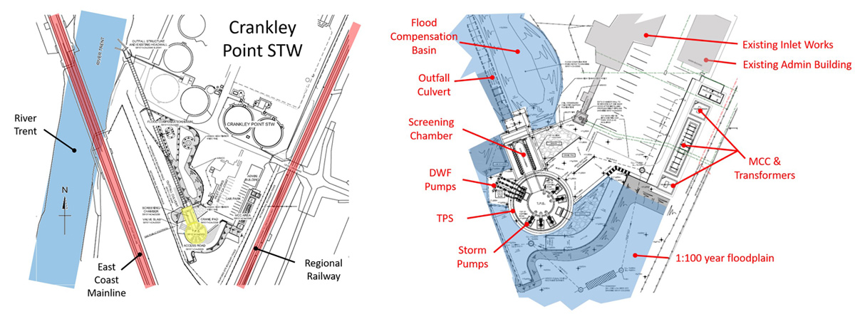
(left) Constraints plan and (right) site layout – Courtesy of nmcn PLC
Site constraints
As can be seen from the plan (above left), the proposed site is constrained by adjacent railways lines to the south and east.
The River Trent is to west and to the north is the inlet works, to which a connection was to be made, the remainder of the treatment works, and the A1. Due to this the only point of access for construction was via the existing site access which was by means of a user worked level crossing over the Nottingham to Lincoln Railway.
Due to its depth and proximity to Network Rails assets, the TPS was considered to fall within the zone of influence of both railways; infrastructure of national significance. The TPS would need to conform to Network Rail’s Engineering Assurance of Building and Civil Engineering Works.
The proposed site was located within the flood plain of the River Trent (Flood Zone 1) requiring floodplain compensation be provided for any loss of floodplain volume as a result of the proposed works.
Solutions
With such significant constraints, a multi-disciplinary team was established to collaboratively develop the design. This consisted of Principal contractor/MEICA designers BNMA, civil designers GHD, pump supplier Xylem Water Solutions, physical modelling and hydraulic specialists Hydrotec Ltd and STW client and operations representatives.
The site posed numerous challenges which required careful and considered thought in order to provide a robust, readily constructible and safe design:
- With significant access issues there was a particular drive to minimise the size of the proposed development and material volume; both construction material in, and excavated material out.
- To complement this there was a drive to minimise the plan area of the development to reduce the size of the flood compensation required, which was limited on such a small site.
- A robust method of shaft sinking was needed to minimise risk of settlement and avoid dewatering, both of which could have an impact on Network Rail’s assets.
- Mobile crane size and location was critical. A crane collapse could potentially impact on the live treatment works and railways, all cranes collapse radii had to be plotted.
- There was a drive to maximise the use of off-site manufacture which minimised materials to site, improved programme and maximised health and safety benefits by minimising works both at height and within a confined space.
Crankley Point Terminal Pumping Station: Supply chain
- Client: Severn Trent
- Principal contractor: BNMA (Barhale North Midland Alliance)
- M&E designer: BNMA (Barhale North Midland Alliance)
- Civil designer: GHD
- Piling contractor: Murphy International Ltd
- FRC contractor: STAM Construction Ltd
- Physical modelling: Hydrotec Consultants Ltd
- Pump supplier: Xylem Water Solutions
- Screens supplier: Huber Technology
- Mechanical installation contractor: Alpha Plus Ltd
TPS efficiencies
The notional design of the TPS was 20m in diameter, in order to provide sufficient space on plan to divide the pump station into PFF and storm wet wells, by means of a full height dividing wall. The design team were able to reduce the TPS diameter to 15m in diameter which achieved a 25% saving in materials and 40% reduction in excavated material. In turn, this minimised traffic and minimised plan area.
This was achieved by developing an innovative radial arrangement for the storm pumps. This required the introduction of a central core which rises out of the ground allowing the storm pumps to discharge toward the centre of the shaft and into a bowl on top of the central core.
The core provided additional benefits which were seized upon during the design phase. Portals in the core at low level optimised flow presentation to each of the storm pumps. The weight of the core was significant and its central position countered uplift forces on the base, where bending moments are highest, economising the base design. This allowed the base to be thinned out with the exception of the central 7.95m which was thickened by 1m to resist the higher loading of the core, saving 20% in steel and concrete. The diameter of this thickening was aligned to the size of precast concrete ring sections which were used to construct the core; saving programme and minimising work at height. The bowl at the top was formed by a precast corbel ring and landing slab, simplifying construction.
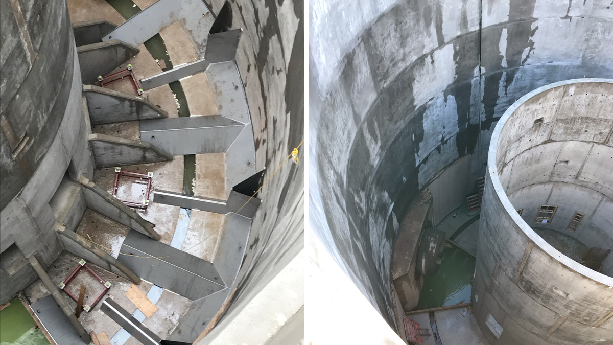
(left) Simplification of complex pump presentation geometry: prefabricated concrete walls and preformed benching in stainless steel and (right) precast concrete core, spray lined internal and tunnel portal – Courtesy of nmcn PLC
The design further utilised precast construction to form flow deflection walls which were embedded within cast in situ benching for stability; avoiding drilling and fixing. In addition, thin-wall stainless steel profiled sections were used in order to form the complex benching requirements. These were grouted afterwards and minimised time spent within the confined space forming benching by hand.
Due to the depth of the shaft the excavation extended into the Mercia Mudstone Group, significantly below the water table. The presence of gypsum bands within the mudstone is a local geological feature and increased risks associated with groundwater. The risk to the adjacent railways was mitigated by installing a secant pile wall which resulted in negligible settlement and eliminated the need for any dewatering. To offset some of the cost of this, the bearing capacity of the secant piles was utilised to support the screening chamber above. Just six additional piles were required (instead of the 40+ originally envisaged) for the screening chamber. These were installed at the same time as the secant pile wall, requiring a single mobilisation/demobilisation of the piling rig over the level crossing. The plan area of the screening chamber itself was reduced by 60% from the notional solution, reducing floodplain compensation requirements.
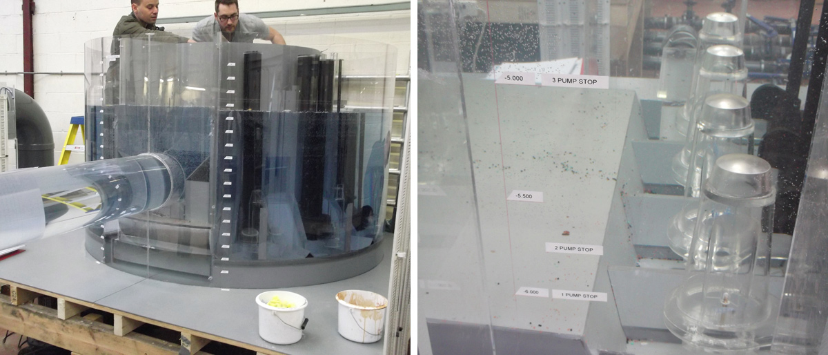
(left) Physical hydraulic modelling of storm sump and (right) physical hydraulic modelling of DWF sump – Courtesy of nmcn PLC
During the detailed design phase, the storm and PFF sumps were physically modelled to 1/8th and 1/4th actual size respectively. The screening chamber was also physically modelled to 1/8th actual size. The models ensured that the final design was hydraulically sound and proved that all areas were ‘self cleansing’ under various conditions. The models were tested under challenging conditions, such as heavy rag and floating solids, which mimicked the differing environments the TPS will be subject to during storm events.
Site layout efficiencies
The new site power and control equipment was sited outside of the 1 in 100 year flood level, while the TPS and screening chambers are within this flood plain. The control equipment was sited adjacent to the existing administration building with line of site to the TPS. This provides Severn Trent Operatives with safe and convenient access to the key components of the site during any storm event.
Further benefits were delivered through the innovative design of the outfall to the River Trent, which utilised the existing storm tank outfall headwall rather than requiring a new one. Through liaison with the Environment Agency a design was developed which involved strengthening the headwall and adding a stilling and combination chamber behind it. This avoided the need for a large cofferdam within the river which would have added significant health and safety risk and environmental impact.
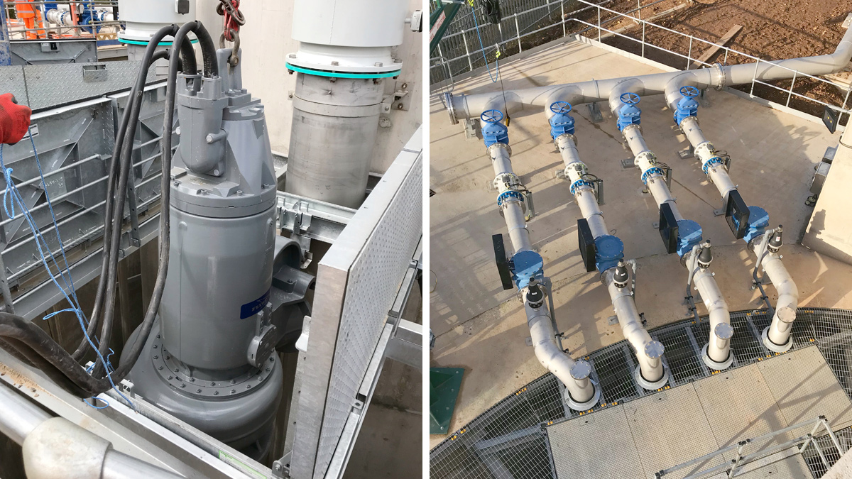
(left) 175KW Xylem Water Solutions storm pump weighting 4.2 tonnes and (right) ctainless steel dry weather flow pipework (300mm diameter) – Courtesy of nmcn PLC
Due to the capacity of TPS, the availability of sufficient commissioning water was a significant design consideration. Final commissioning of the storm and PFF pumps was undertaken with the use of final effluent (FE) from the final stages of the treatment process on the site. The FE was pumped 200m across site from its final discharge chamber to the new TPS. The design of the TPS, screening chamber and emergency overflow allowed easy modification to recirculate water by temporarily blocking the outlet to the River Trent and returning water from the screening chamber back into the TPS via the emergency overflow culvert.
Conclusion
Collaboration was key throughout the design and build phase of the project. A team was formed representing each specialised field (mechanical, electrical, civil) and the whole team spent numerous hours identifying key constraints and the overall project objectives.
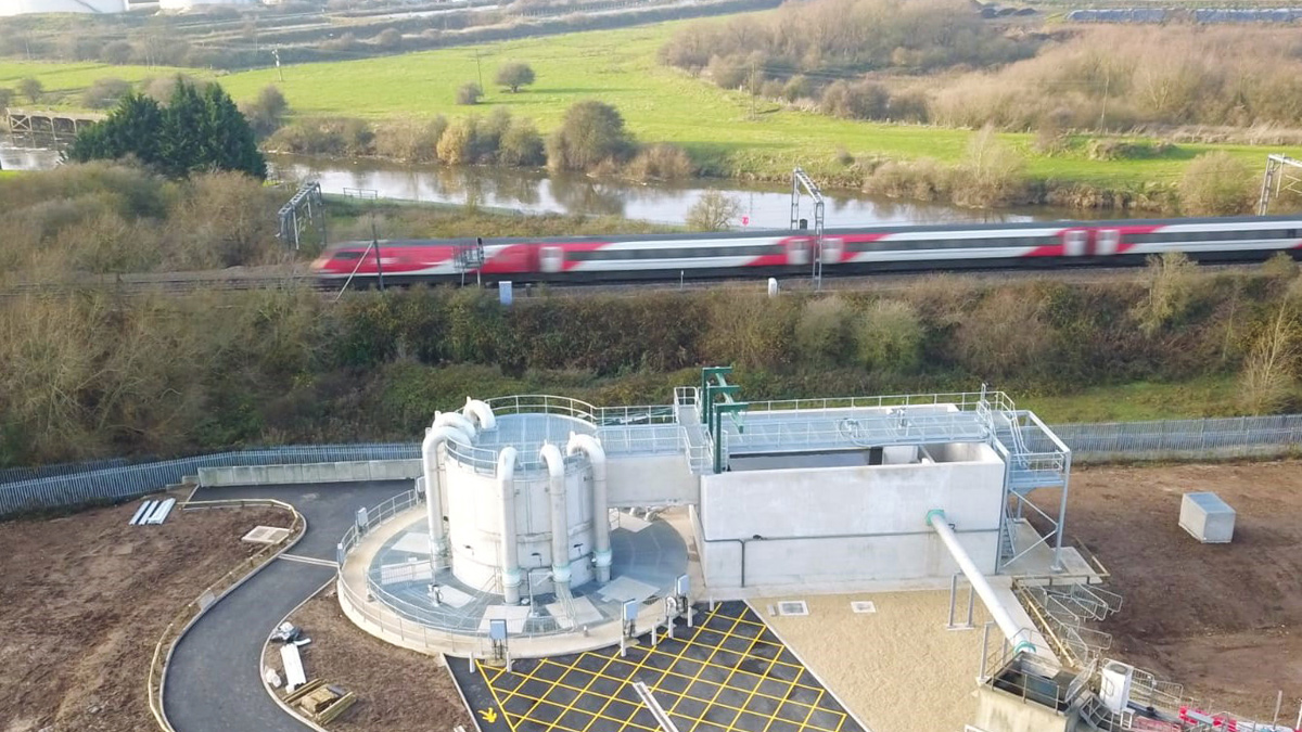
Proximity to the East Coast Mainline with the River Trent and British Sugar beyond – Courtesy of nmcn PLC
The team worked collaboratively to arrive at a solution which took consideration of optimal mechanical and hydraulic performance, minimised the plan area and integrated temporary and permanent works. Each disciplines specialist experience, preferences, opportunities for value engineering were explored to develop an agreed design before commencing with a detailed design phase. This well coordinated design was highly successful, validated by a smooth construction phase with negligible problems encountered during the final build, through commissioning and handover.
The feedback from the client has been exceptional, from a senior management level down to the Operations Team working at Crankley Point on a daily basis. The praise from the Operations Team has been particularly rewarding; how easy they have found the TPS to work with post-handover and that everything is working as intended by design.
The Newark Waste and Water Improvement Project was successful at the recent Institution of Civil Engineers 2019 East Midland Merit Awards Dinner winning the Large Project (£10m+) Award for the year.