
Etruria Vale 1 CSO & Detention Tank (2026)
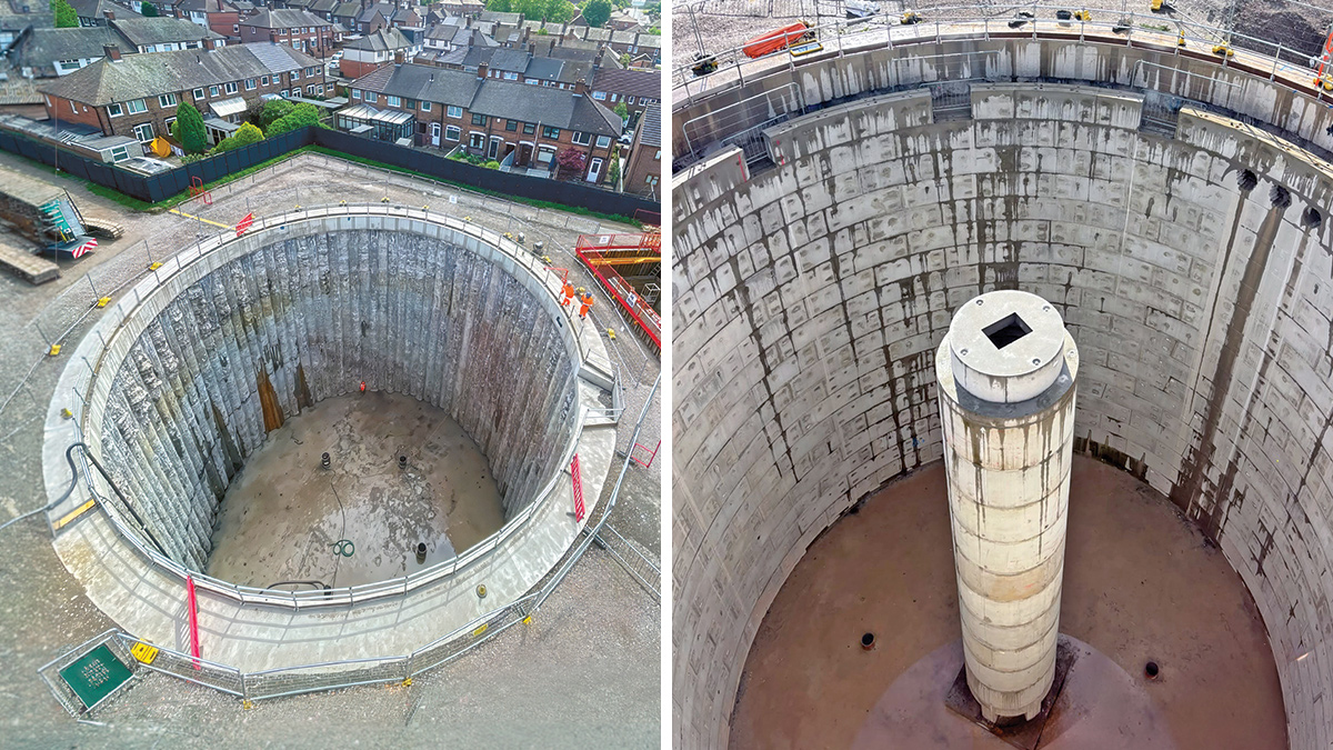
(left) Completed secant piled temporary works and (right) central support and VacFlush™ column - Courtesy of Barhale
Located in the Etruria area of Stoke-on-Trent, this project addresses a long-standing issue associated with a combined sewer overflow (CSO) known as Etruria Vale 1 CSO. Prior to this scheme, stormwater spills were regularly triggered from the CSO during periods of heavy rainfall, affecting water quality and the overall condition of the receiving watercourse, Fowlea Brook. The project is therefore being delivered as part of Severn Trent’s AMP7 WINEP programme, and it will significantly reduce the frequency and volume of spills to the local environment, enhancing river quality in Fowlea Brook.
Hydraulic modelling & option development
The Etruria project comprised five CSOs discharging to the Fowlea Brook via two outfalls. The hydraulic model was subsequently re-verified and used to assess the baseline and 2050 design horizon, including growth and a 20% climate change uplift, to determine CSO performance. Time series rainfall assessments were undertaken for the water quality assessment.
Interventions assessed included offline storage at three CSOs and upstream surface water separation. Although surface water diversion reduced spill frequency, limited water quality benefits and increased downstream flood risk associated with a new outfall led to this option being discounted.
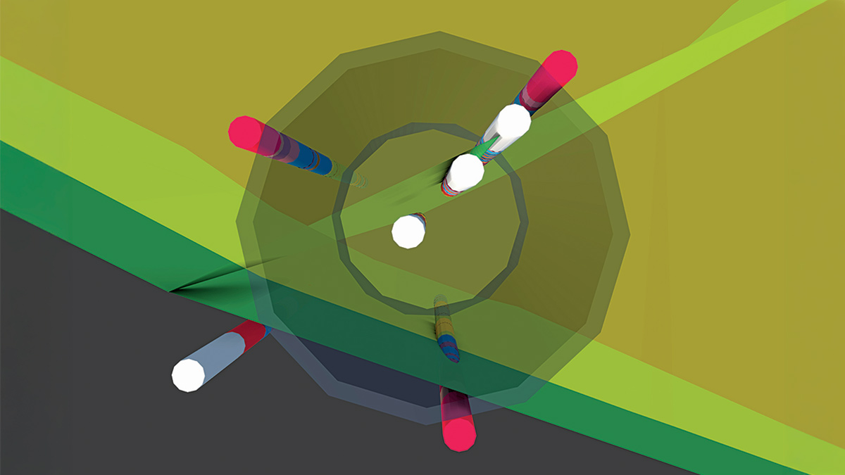
Ground model and fault lines plan – Courtesy of SLR Consulting Ltd
The preferred strategy focused on reducing spill volumes by providing storm storage at key CSOs. Further analysis identified Etruria Vale 1 and Lower Oxford CSOs as the most influential assets for improving compliance against both ammonia and biochemical oxygen demand (BOD) drivers.
Streamlined optioneering processes included water quality target spill volume reductions for both baseline and future design scenarios. These targets aided evaluation of hydraulic options by quickly eliminating options that could not meet the required target volumes and standards for ammonia and BOD, along with Fundamental Intermittent Standards (FIS).
Several offline storage configurations were assessed upstream of Etruria Vale 1 CSO. Although increased storage reduced spill frequency and BOD loading, full ammonia and DO compliance could not be achieved because pollutant contributions from upstream CSOs outside the project boundary remained. Complementary upstream improvements will deliver catchment-wide compliance.
Preferred option
The preferred solution comprised offline storage located upstream of Etruria Vale 1 CSO, avoiding land, planning and space constraints whilst delivering the required reduction in spill frequency and volume. Although challenging ground conditions affected the site, it was considered the most suitable location from both hydraulic and operational perspectives.
A 5,200m3 offline detention tank was selected as the preferred option within an existing area of public open space. The proposed structure comprises a 20m internal diameter shaft with an approximate depth of 22m. Flows exceeding three times dry weather flow (3DWF) are diverted into the storage facility via a 1,200mm diameter overflow sewer.
The tank is located upstream of an existing online storage tank and associated flow control chamber, and the interface between the two assets ensures the network’s storage capacity is maximised in storm conditions.
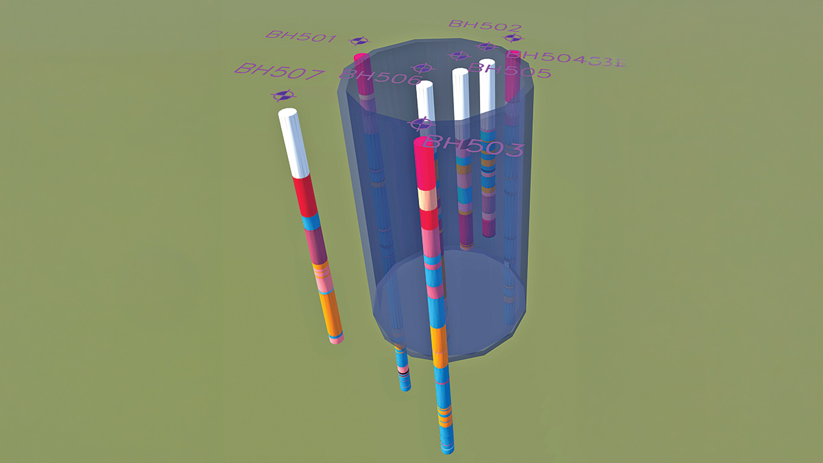
Strata profile from boreholes within shaft footprint – Courtesy of SLR Consulting Ltd
To control the maximum top water level (TWL) within the shaft during extreme storm events, a 1050mm emergency overflow connection was incorporated, discharging downstream of the existing flow control chamber. This arrangement improved operational resilience whilst maintaining acceptable hydraulic performance within the network. Stored flows are returned from the storm tank via a 450mm diameter rising main when the downstream network has sufficient hydraulic capacity.
A VacFlush™ vacuum flushing system from CSO Group was selected to provide effective tank cleaning and sediment removal following storm events. This solution was particularly suitable given the need for a central structural column to support the shaft cover slab. The selected system also provides robust whole-floor cleansing and minimises long-term operational maintenance requirements.
The final water quality assessment demonstrated significant environmental benefits. The BOD objective was achieved, but residual ammonia and one-hour DO FIS non-compliances were attributed to wider catchment influences beyond the project boundary. Complementary upstream improvements will deliver full compliance within the receiving watercourse.
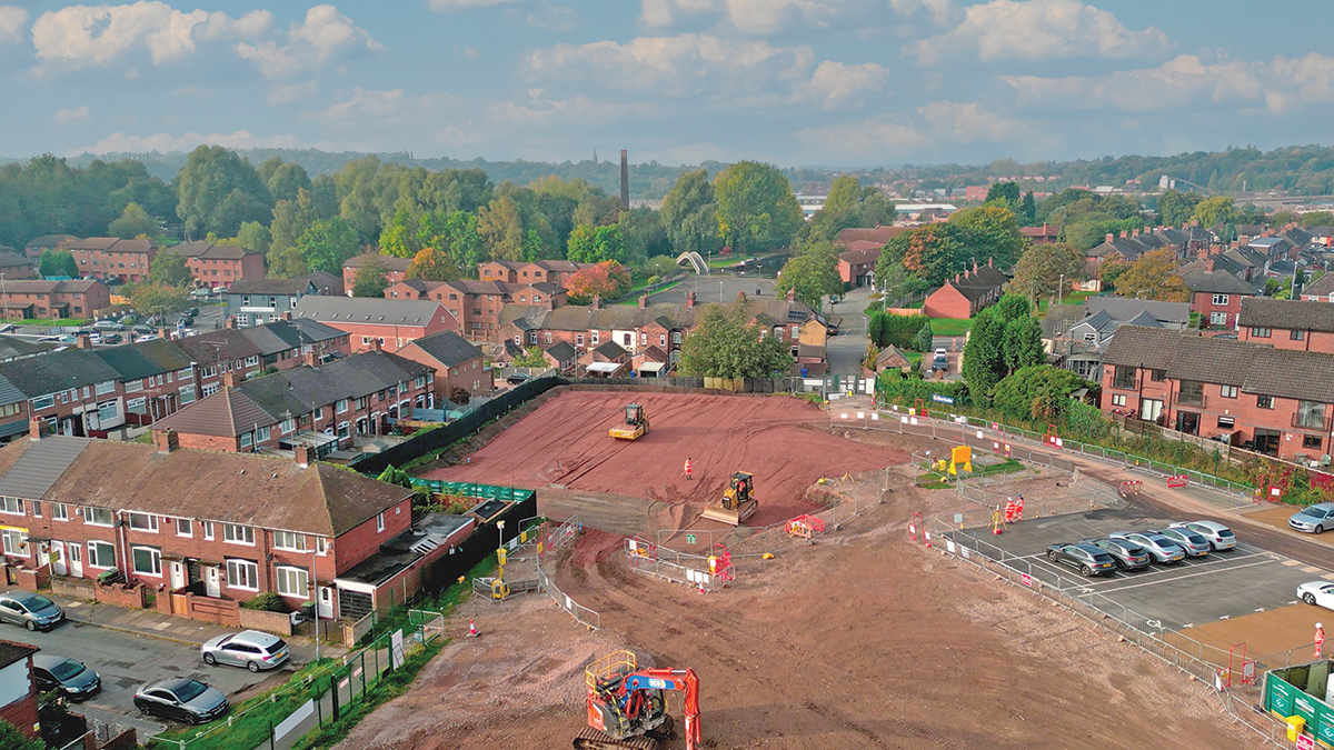
Site preparation – Courtesy of Barhale
Etruria Vale: Supply chain – key participants
- Main contractor & temporary works: Barhale
- Project management: Aqua Consultants Ltd
- Structural & geotechnical: GHD
- Secant piling design: Expanded Piling
- Coal risk & ground modelling: SLR Consulting Ltd
- Physical modelling: Hydrotec Consultants Ltd
- Ground investigation: Socotec
- Reinforced concrete: Wrekin Civil Engineering Ltd
- Geotechnical consultant: Jord GeoDesign
- MEICA: Ferntec Ltd
- Water quality: Intertek Ltd
- Precast items: FP McCann
- VacFlush™ system: CSO Group Ltd
- Screening: Huber Technology
- Monitoring: Murphy Geospatial
- MCC units: RSE Control Systems (Blackburn Starling)
- Secant piling & fissure grouting: Keller Ltd
- Concrete supply: Cemex
- Aggregates & disposal: SL Walchester
- Plant & temporary equipment: BCS Group
Geology & geotechnical considerations
The preferred site is located within an area of public open space and is suitable for the detention tank footprint and associated buildability considerations. However, known coal mine workings and mine entries to the north constrained the footprint.
Locating the structure in this area would have required additional investigation, treatment of mine workings, and a deeper or larger-diameter detention tank to accommodate the associated ground treatment measures. Consequently, the final detention tank layout was carefully positioned to avoid these constraints while maintaining project viability and minimising construction risk.
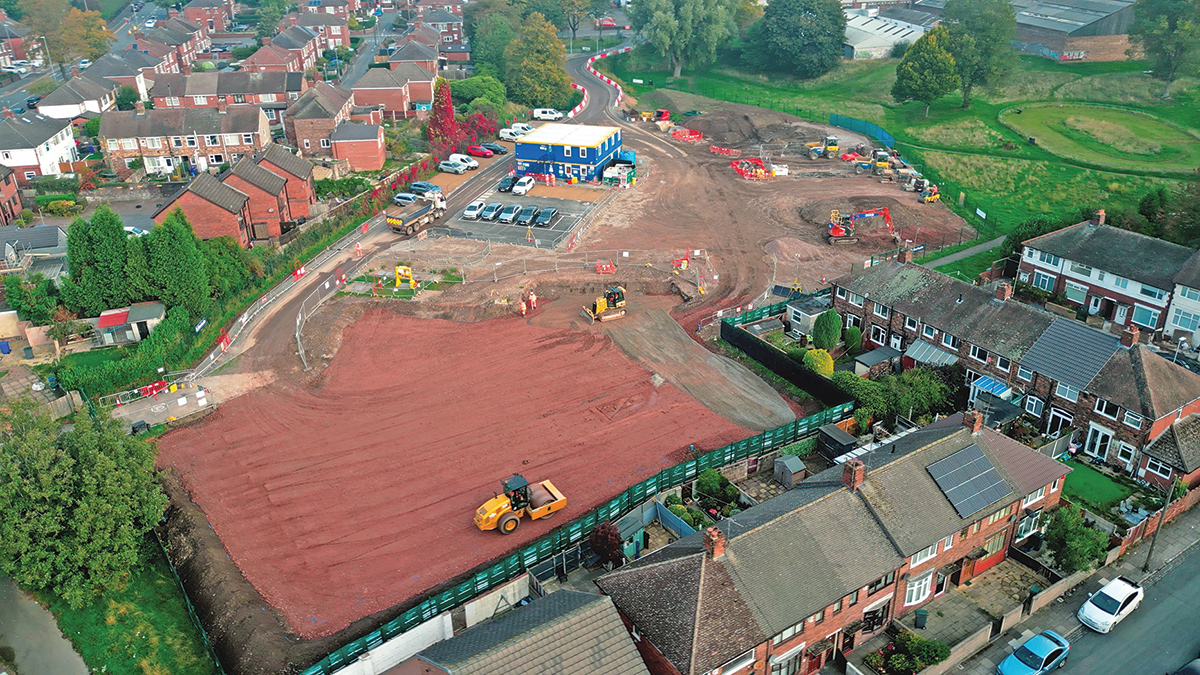
Site preparation – Courtesy of Barhale
Excavation design
The proposed detention tank was found to intersect another of the geological constraints to the project, the Shelton Fault zone, comprising approximately 20-30m of fault-disturbed ground with highly fractured and variable rock conditions.
This meant the excavation and construction methodology had to accommodate potentially variable rock strength, increased instability risk and unpredictable ground behaviour during construction.
Mining risk & foundation design
The investigations confirmed the presence of shallow coal seams but found no evidence of shallow mine workings or mine entries beneath the proposed detention tank. This improved confidence that:
- Extensive mining remediation was not required.
- Long-term ground stability risks were low.
- The permanent structure could be designed without adopting highly conservative assumptions for mine collapse hazards.
Groundwater management & base slab design
Artesian and sub-artesian groundwater conditions were identified during the ground investigation. This significantly influenced:
- Dewatering requirements during construction.
- Assessment of water ingress into the detention tank excavation.
- Design of the concrete base plug to resist uplift and flotation.
- Construction sequencing to maintain excavation stability.
Without the ground investigation data, these groundwater risks would have been difficult to quantify and could have led to significant over-design or construction challenges.
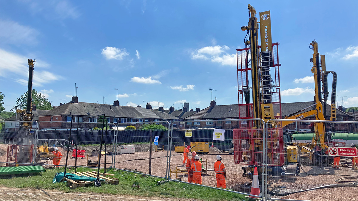
Plug grouting operations – Courtesy of Barhale
Ground gas & operational safety design
Although methane was not detected, faulting, Made Ground and shallow coal seams presented potential pathways for carbon dioxide and mine gas migration. This informed:
- Construction phase gas monitoring and ventilation requirements.
- Confined space procedures during excavation.
- Permanent ventilation and maintenance access arrangements for below-ground chambers requiring manned entry.
Buildability & construction methodology
Perhaps the most important outcome was that the phased Ground Investigation transformed the project from one with significant geological uncertainty into one with a well-defined ground model.
This enabled the design team to:
- Validate the detention tank concept.
- Develop realistic temporary works solutions.
- Quantify groundwater and mining risks.
- Secure Mining Remediation Authority approvals for ground investigation, temporary works and incidental coal removal.
- Progress detailed design with significantly greater confidence.
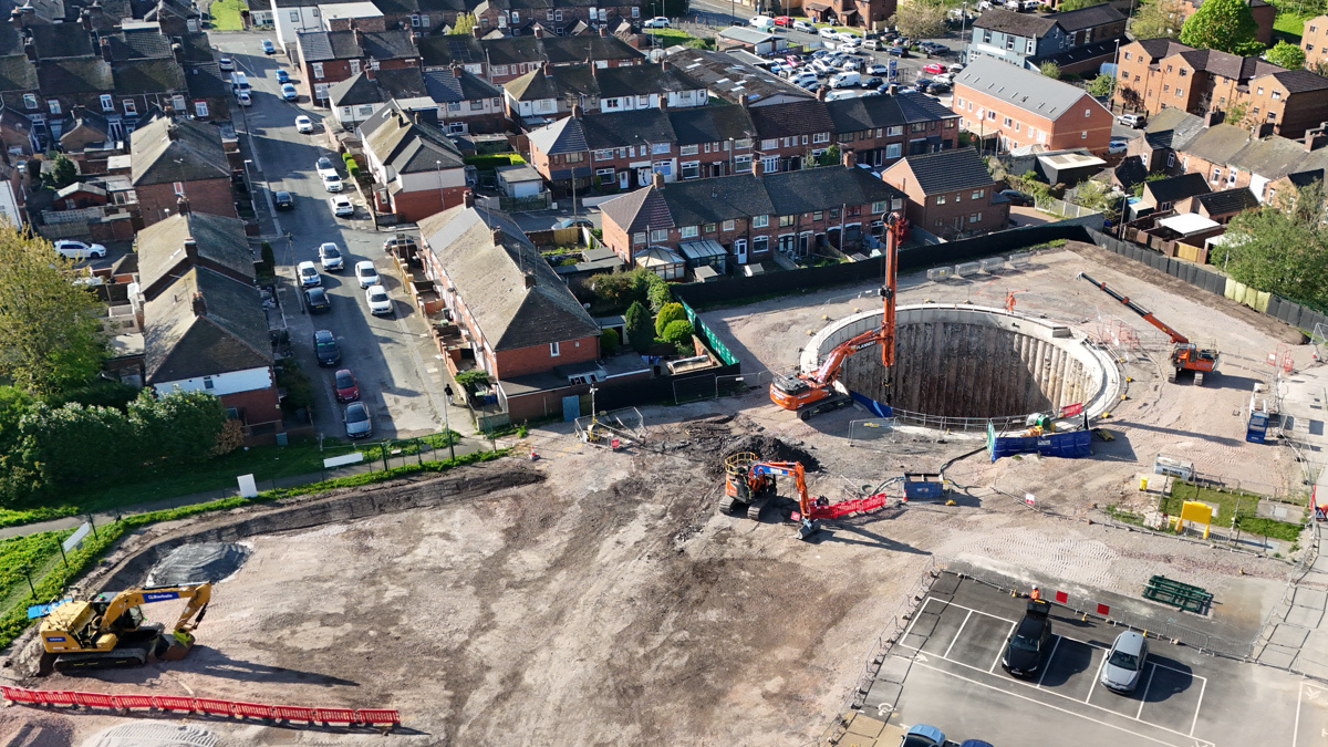
Shaft excavation – Courtesy of Barhale
Permanent & temporary works design collaboration
A Geotechnical Baseline Report (GBR) was produced for Severn Trent by their design consultant, GHD, to clarify expected ground conditions so the contractor, Barhale, could confirm construction methodology and pricing.
A key feature of the GBR was that it did not treat the permanent and temporary works as isolated packages. The GBR identified the main permanent works elements – including the detention tank, valve chamber, crane pad, pump laydown pad and vent stack foundation – and brought together the relevant GHD structural design reports with the Expanded Piling secant pile design report. The baseline construction methodology explicitly tied the geotechnical baselining to those design reports.
All parties actively collaborated during the GBR review process, which included issues such as the strength profile for shaft excavation, the deeper temporary works profile for fissure grouting/grout curtain, and clarification of permeability. The GBR was then updated to include the added comments and highlighted changes.
A collaborative approach adopted between the contractor and permanent and temporary works designers ensured the permanent and temporary works were not considered as isolated packages. This collective approach ensured the chosen solution mitigated the risks associated with working in this type of environment from the outset.
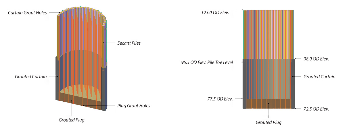
Secant piling & fissure grouting – Courtesy of Keller Ltd
The ground investigation reports indicated shallow and artesian groundwater strikes during borehole drilling and groundwater monitoring. This indicated high hydrostatic uplift pressures on the base of the excavation, with the potential to destabilise the excavation base and allow water ingress to an extent likely to be unmanageable without additional measures. The deep-seated fissure-grouted ‘plug’ with grout curtain creates a reduced-permeability zone below and around the shaft excavation, the weight of which will temporarily resist uplift at the base of the excavation.
The grouting works were installed first, with the rotary bored secant piled wall installed with toe levels extending into the grouted curtain. The grout used was a micro-fine cement-based grout with a naphthalene sulphonate-based dispersant/super-plasticiser.
The solid geology on site is the Etruria Formation and Pennine Coal Measures, consisting of weathered, variable-strength mudstone, siltstone, sandstone, and coal. The rock is highly fissured, and the area has known faulting, as well as coal seams likely to have been worked at shallow depth. This drove the design of the secant piled wall and excavation support system. Temporary works designers considered the potential for local instability, variable drilling conditions and groundwater inflows during piling and excavation operations.
The shaft itself was formed by constructing a circular secant piled wall with toe levels extending into the grouted curtain. When excavated, the secant piled wall will work in hoop stress to retain the surrounding soil, leaving a clear 22.9m diameter shaft to approximately 21.0m excavation.
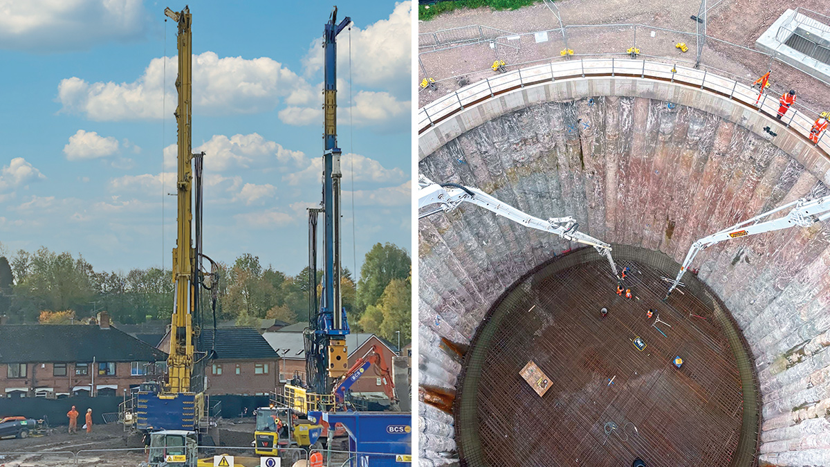
(left) Twin secant piling rigs and (right) Shaft base slab concrete pour – Courtesy of Barhale
The piles are fully cased, rotary-bored piles. The interlocking secant wall was created by installing ‘primary’ piles formed with firm concrete and are not reinforced. ‘Secondary’ piles were installed with structural concrete and are reinforced. These were installed by drilling through the primary piles to create an interlocking wall.
A bottom-up segmental lining, erected from the base slab, has been adopted for the shaft. The cementitious lining to the secant pile wall has been omitted to minimise long-term maintenance needs.
Through a collaborative approach to the permanent and temporary works design interface, the main permanent structure is designed to tie into the temporary structure, reducing the need for an excessive concrete plug. Instead, the concrete surrounding the shaft was used, saving the project valuable time, money, disruption, and carbon footprint.
Progress to date
By February 2026, grouting and secant piling works were complete, enabling excavation of the 22m deep detention tank. A reinforced concrete pile cap was installed around the shaft perimeter to accommodate construction loading from heavy plant. Two excavators operated within the shaft throughout the excavation to maximise productivity, while approximately 60 tipper wagons per day removed excavated material for beneficial reuse across the Midlands. Following excavation to formation level, over 800m3 of concrete was placed to form the detention tank base.
The permanent shaft structure comprised reinforced concrete precast segments installed from the base upwards within the secant piled shaft. By integrating the temporary and permanent works, the team has maximised productivity by constructing the permanent shaft as excavation activities concluded.
Concurrent with the shaft construction, works also progressed on the valve chamber structure, which will house the three discharge pipelines from the detention tank. These flows will be throttled into a single 450mm diameter rising main before discharging into the downstream discharge chamber. Delivering these works in parallel has maintained programme momentum and enabled multiple work fronts to progress simultaneously.
Value engineering initiatives have facilitated the off-site manufacture of a precast MCC trough. This approach has removed the need for traditional in situ construction, reducing programme duration, improving quality, minimising site labour requirements and delivering both cost and carbon savings.
Throughout construction, the temporary/permanent works design interface continued through technical queries & responses. The continued collaborative approach has facilitated timely reviews to maintain project progress.
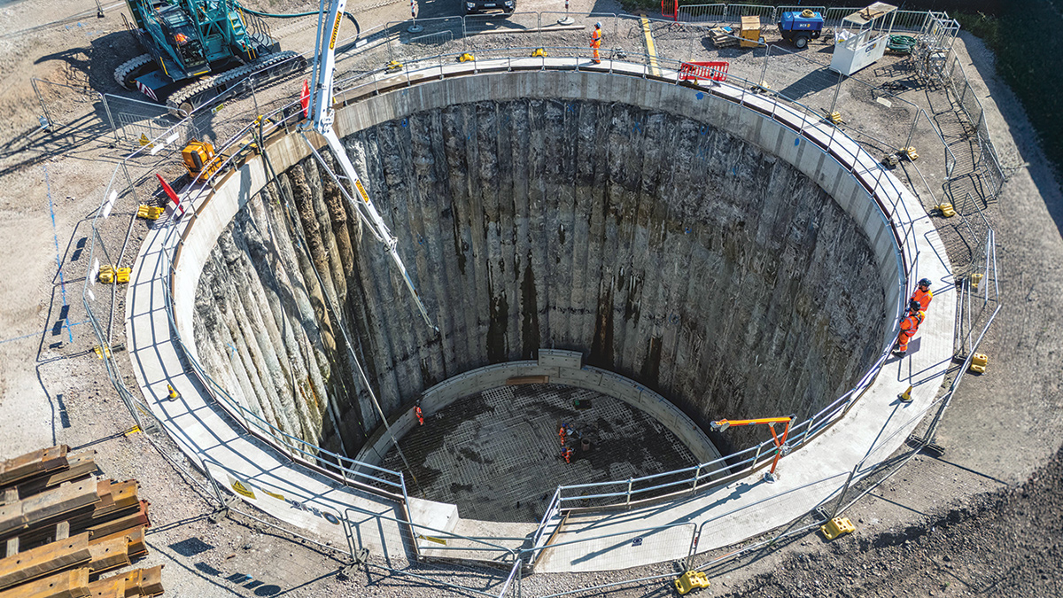
PCC shaft construction – Courtesy of Barhale
Conclusion
Severn Trent needed to improve river quality in Fowlea Brook, Stoke-on-Trent. Through targeted hydraulic and water quality modelling, introducing network storage to the Etruria Vale 1 CSO provides the significant improvements needed in water quality.
Providing that storage required extensive ground investigation and geological modelling to reduce uncertainty associated with geological faulting, groundwater, coal seams and former mining, which directly influence the design and construction methods.
The project team’s collaborative approach to design and delivery demonstrates how certainty in outcomes can be achieved in a challenging environment.
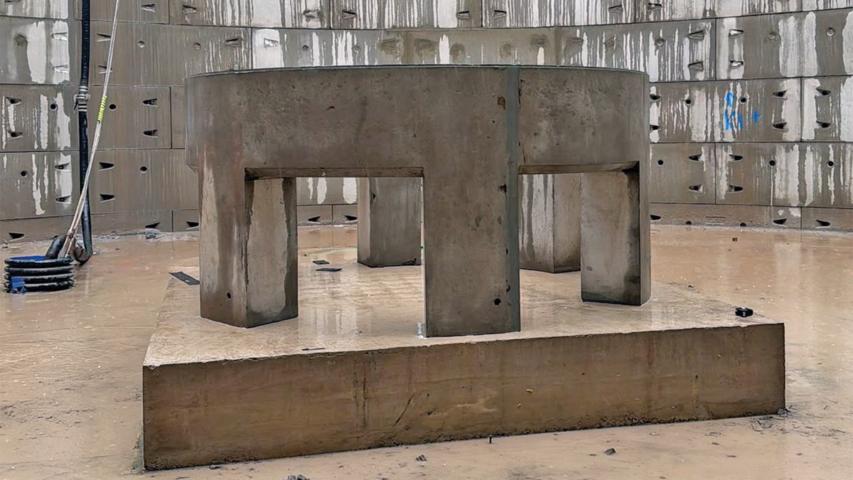
VacFlush™ base - Courtesy of Barhale