
Killinghall STW (2025)
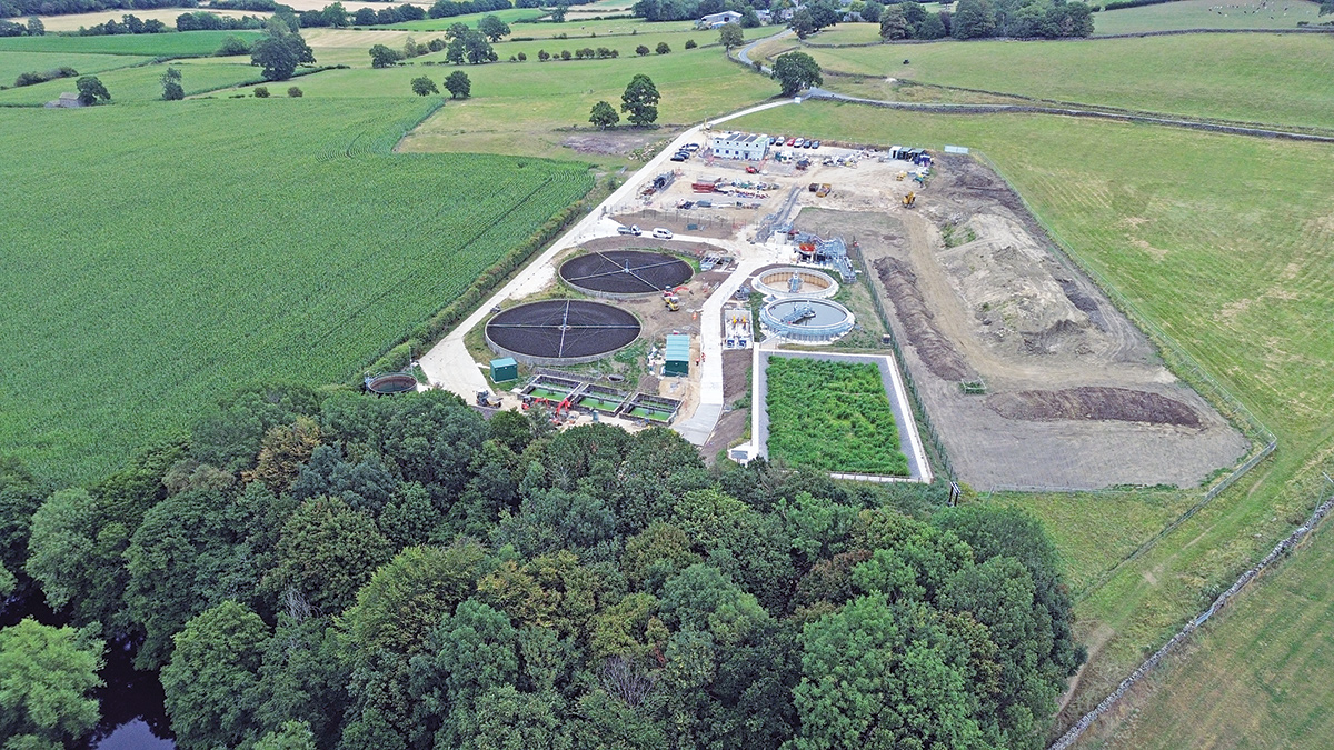
Killinghall STW (August 2025) - Courtesy of MMB
Located approximately 5km north of Harrogate, Yorkshire Water’s Killinghall Sewage Treatment Works (STW) receives flows by gravity from Killinghall, as well as pumped flows from the nearby village of Hampsthwaite, serving a total population equivalent of 3741. Built in the 1970s, the site’s capacity has not kept pace with Killinghall’s growing population. The existing site consisted of an inlet reception chamber, a duty-only screen, a flow measurement flume, three primary settlement tanks (PSTs) with desludge system, two mineral media filters (MMFs), three humus settlement tanks (HSTs), a sludge storage tank, as well as ancillary pumping systems for recirculation, washwater and site drainage.
Project drivers
The scheme sought to address two key issues that were the drivers for the project.
- Phosphorus removal: The first driver relates to a new total phosphorus consent being established by the Environment Agency to an average annual limit of 0.7 mg/l and new total iron consent of 4mg/l (95%ile) at the consented Dry Weather Flow (DWF) discharge of 1,631m3/d. This part of the scheme falls under the Water Industry National Environment Programme (WINEP) and had a regulatory compliance date of December 2024.
- Flow balancing: The second driver concerns the undersized existing works, which struggles handling peak flows caused by Killinghall’s growth. This has led to hydraulic problems and frequent operator intervention during high-flow periods. Killinghall STW is designated as a treat-all-flows works, so the site does not have a storm storage or discharge permit. A flow survey established a maximum measured incoming flow of 155 l/s whilst the site itself was originally designed for 60 l/s.
In response to these requirements, Mott MacDonald Bentley (MMB) commenced work on a £15m scheme in December 2023, encompassing the comprehensive design and construction of a new inlet works, all new primary treatment facilities, expanded secondary treatment capacity, and associated ancillary works.
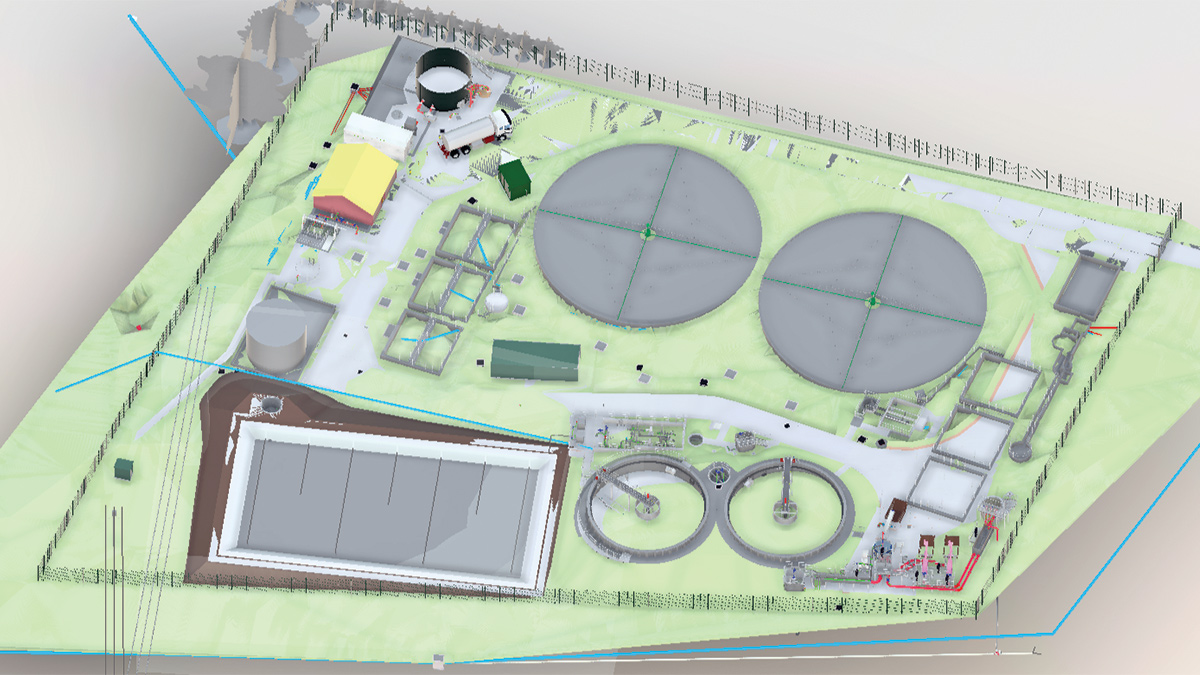
Killinghall STW 3D model – Courtesy of MMB
Solution development
The project underwent substantial modifications to its original scope, seeking environmental benefits and operations efficiencies. Numerous potential solutions were explored during the early stages of the project, with the favoured solution originally including three new 16.0m diameter primary settlement tanks (PSTs), two new 9.4m diameter plastic media filters (PMFs), and three new 17.0m diameter humus settlement tanks (HSTs).
This solution was thoroughly evaluated both in terms of buildability and assessed for its carbon cost implications. It would have involved extensive hard infrastructure, resulting in considerable embodied carbon costs. Significant construction challenges were also identified due to the restricted space within the existing site boundary.
The project team established a strong working relationship with the Yorkshire Water and the Yorkshire Water’s strategic planning partner Stantec UK, working collaboratively to refine the scope as the project moved towards detailed design.
The decision was made to reduce the number of new PSTs from three to two, whilst completely removing the PMFs and HSTs. In their place, an 861m2 vertical flow sub-surface aerated reed bed was introduced. It was agreed that the existing humus settlement tanks would be retained, with the flow to them limited to 60 l/s, which they were originally designed for. Any flows exceeding 60 l/s would be directed to the new aerated reed bed, essentially establishing two streams for secondary treatment; one to treat typical daily flows, and another to treat flow peaks during heavy rainfall events.
The two streams then combine in the final effluent chamber, before discharging to the River Nidd via the works’ outfall.
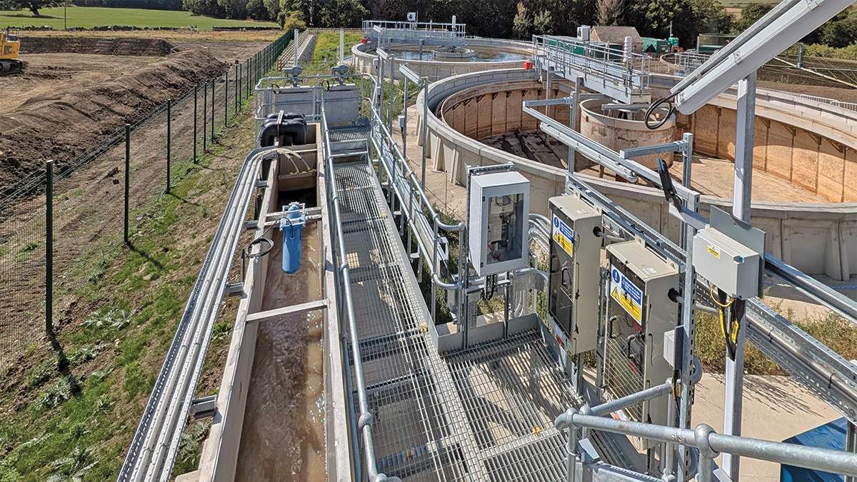
New flow measurement channel and chemical point of application area (August 2025) – Courtesy of MMB
Killinghall STW: Supply chain – key participants
- Principal contractor: Mott MacDonald Bentley
- Process design: Stantec UK
- Ground surveys: Dunelm Geotechnical & Environmental
- Groundwater investigation: WJ Group
- LV electrical installation: Circle Control & Design Systems
- Mechanical installation: Alpha Plus Ltd
- FRC: G&F Formwork Ltd
- Metalwork: Fab-Tek Installations Ltd
- MCC & software: Total Automation & Power
- MCC kiosk: Quinshield Ltd
- Aerated reed bed: ARM Ltd
- PST precast panels: Naylor Concrete Products Ltd
- PST half bridge scrapers: JBF Group Ltd
- PST auto-desludge RAM pumps: EMS Industries Ltd
- 3D-printed chambers: Hyperion Robotics
- Submersible pumps: Xylem Water Solutions
- Valves: Affco Flow Control (UK) Ltd
- Spiral screens: Jacopa Ltd
- Grit removal: Tuke and Bell Ltd
- Upward flow screen: Huber Technology
- Sludge tank: Goodwin Tanks Ltd
- Sludge tank mixer pump: Xylem Water Solutions
- Penstocks: Waterfront Fluid Controls Ltd
- Syphon chamber stoplogs: IBS Engineered Products Ltd
- Ferric storage & dosing, washwater kiosk: NPS Engineering Group
- Trace heating & lagging: Waste Water Manufacturing (WWM)
- Fabricated chambers: George Green (Keighley) Ltd
- Temporary treatment: Siltbuster Group
- Automatic filter: Bollfilter UK Ltd
- Lifting equipment: Peter Cassidy (Leeds) Ltd
The solution
Inlet pumping station
A new inlet pumping station has been constructed at the head of the works to receive flows from the Killinghall gravity main and lift them to the new inlet reception chamber. The pumping station was introduced to prevent the gravity main from surcharging which otherwise would potentially have led to settlement in the main during low flow conditions. The pumping station consists of three submersible pumps running duty/assist/standby.
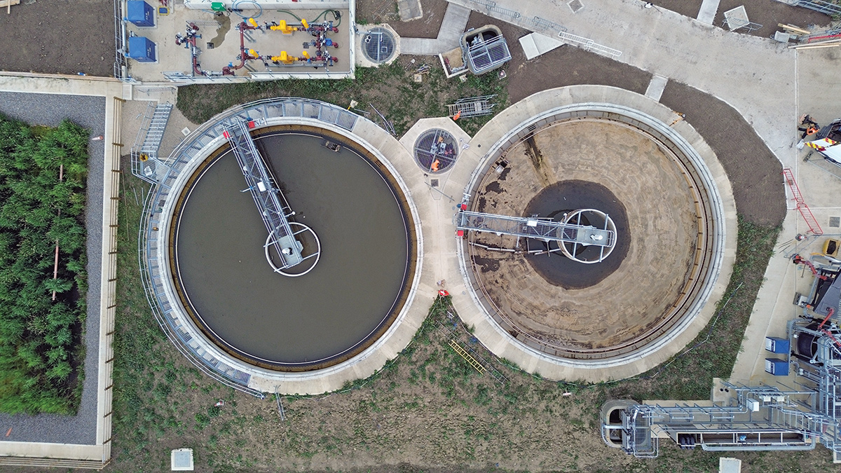
Bird’s eye view of the new PSTs (August 2025) – Courtesy of MMB
Inlet works
New duty/standby spiral screens have been installed rated for a flow capacity of 80 l/s. These are containerised units with DN300 inlet and outlet connections. To supplement the spiral screens, a new upward flow screen has been installed within the inlet reception chamber, which is located upstream of the spiral screens. Any flow exceeding 80 l/s will back up and pass through the upward flow screen up to a maximum of 75 l/s, therefore providing a combined total screening capacity of 155 l/s. Downstream of the screens is a new vortex grit removal system complete with duty/standby airlift blowers. The grit system is sized for the maximum flow of 155 l/s. A grit bypass chamber has been installed complete with manual isolation penstocks should the grit system ever need to be taken out of service for maintenance.
Primary settlement tanks
Two new 16m diameter PSTs have been constructed, together with an auto-desludge system. Each tank was constructed using 48 precast panels with an in situ hopper and floor slab, with each tank having a half bridge scraper to direct settled sludge to the hopper, and to remove scum from the surface of the effluent in the tank. A distribution chamber was installed upstream of the PSTs to split the flow evenly across the two tanks.
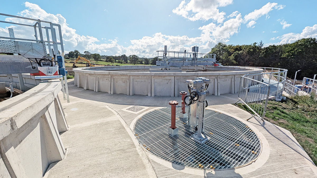
PSTs drain down chamber (August 2025) – Courtesy of MMB
The chamber was constructed out of 3D-printed sections which were then assembled on site. The auto-desludge pumping station comprises two RAM pumps, drawing sludge from the hopper at the bottom of each tank, and pumping it to the new sludge export tank. The pumps can also return the contents of the tank to the distribution chamber upstream of the tanks as part of the automated drain down sequence.
Aerated reed bed
A new vertical flow sub-surface aerated reed bed receives any flows that exceed the capacity of the existing MMFs and HSTs. The aerated reed bed offers an effective, low-energy solution by combining natural biological processes with enhanced oxygenation. This made it ideal at Killinghall for supplementing the existing secondary treatment assets, receiving peak flows to allow the MMFs and HSTs to treat up to the maximum flow they were originally designed for.
A second 3D-printed chamber was installed, this time downstream of the new PSTs, to split the flow between the existing process stream (MMFs and HSTs) and the new aerated reed bed. A modulating penstock in the chamber ensures that the first 60 l/s is directed to the existing process stream. Any flow above this spills to the aerated reed bed. An intermittent wetting flow ensures the contents of the reed bed are turned over periodically. The ability for the reed bed to blend into the local landscape adds ecological and aesthetic value, supporting biodiversity whilst providing sustainable wastewater management.
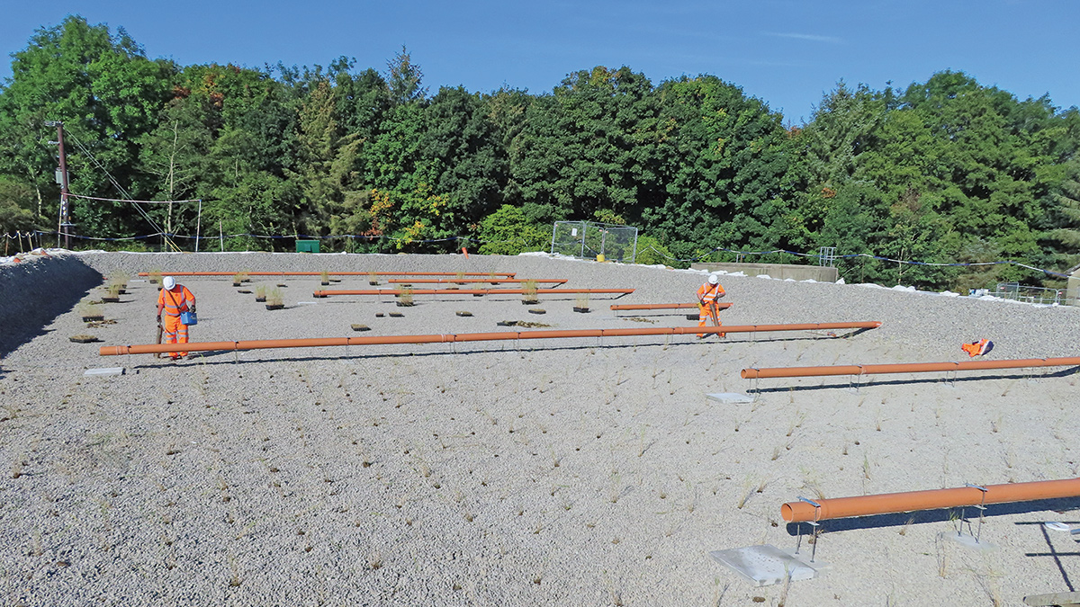
Planting underway in the aerated reed bed (September 2024) – Courtesy of MMB
Ferric storage & dosing
To achieve compliance with the new phosphorus discharge consent limit of 0.7 mg/l, ferric sulphate is dosed downstream of the inlet works. As such, a new ferric storage and dosing kiosk has been installed. The kiosk houses a 5m3 chemical storage tank as well as a dosing rig that consists of duty/standby dosing pumps.
Sludge export tank
Sludge from the PSTs is pumped to a new 175m3 sludge export tank, which is a cylindrical sectional steel tank. The tank is equipped with a decant tree plus a duty-only mixing pump located external to the tank, connected to an ejector within the tank.
Recirculation pumping station
The existing final effluent chamber has been modified to accommodate the installation of two new recirculation pumps. The pumps deliver flows upstream of the primary settlement tanks to ensure the maximum retention time in the PSTs is not exceeded.

New ferric kiosk, sludge export tank & delivery bay (July 2025) and (inset) 3D model – Courtesy of MMB
Washwater kiosk
A new kiosk has been installed housing a 1.5m3 break tank together with a skid-mounted set of booster pumps. A feed from the new recirculation pumping station passes through a new automatic filter located within the existing pump house, before discharging into the new break tank.
The booster pumps deliver washwater to the new spiral screens at the inlet works, as well as to various hose points around site.
MCC
To provide power and control for all new equipment, a new MCC has been installed within a new GRP kiosk. This is fed from a new 115 kVA pole-mounted transformer, replacing the previous transformer that was removed to create additional space for new assets on site.
Carbon reduction through 3D-printed concrete
During the development of the solution and through detailed design, reducing carbon was at the forefront of the project.
Significant carbon savings have been achieved through challenging the scope and replacing hard infrastructure with the aerated reed bed, but further to that opportunities were also realised through alternative manufacture, assembly and construction techniques. The project team wanted to explore the capabilities of 3D-printed concrete and elected to use it for constructing the distribution chambers either side of the PSTs. The chambers were 3D-printed in sections by Hyperion Robotics within a factory-controlled environment before being deliver to site for installation.
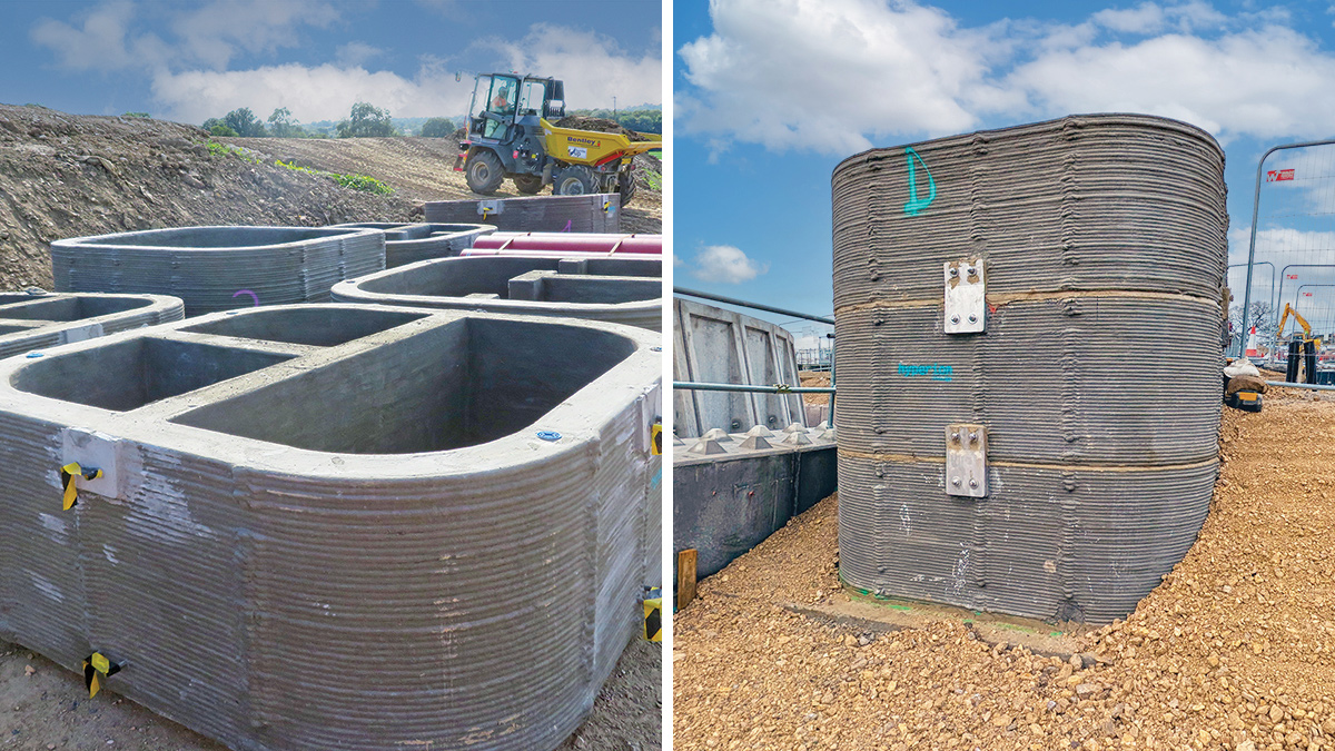
(left) 3D-printed chamber sections awaiting installation and (right) the 3D-printed chamber sections assembled – Courtesy of MMB
Due to the nature of 3D-printing, it allowed for more flexibility with regards to the geometry of the chamber, allowing the corners of the chambers to be rounded off. This in turn meant that the wall thickness of the chambers could be reduced from 300mm to 200mm. Compared to a conventional square chamber with 300mm thick walls, the 3D-printed alternatives represented a 53% carbon saving. By 3D-printing the chambers, it streamlined the installation process, which contributed to a leaner and more sustainable construction phase.
Reducing on-site construction through DfMA
To reduce on-site activity, the Design for Manufacture and Assembly (DfMA) engineering methodology was used extensively. By taking a lot of what would ordinarily be on-site construction activities and placing them in controlled factory environments, less machine time was required on site and less waste was produced.
This can be seen at the inlet works where instead of more conventional concrete channels and chambers, the inlet reception chamber, grit bypass chamber and flow measurement channel were all fabricated off site. With containerised screens also being used, it meant that to complete the installation of the inlet works, the various chambers and screens would be connected by pipework.
Furthermore, the grit tank was also fabricated off-site, rather than cast in concrete in situ. To allow this to be done, and for the system to work hydraulically, a chamber was formed using precast rings to partially bury the tank below slab level.
Another area where the principals of DfMA were employed was at the PSTs, where each tank was constructed using 48 precast panels. The project team selected a standard panel size from the supplier to best suit the required volume according to the process calculations. Compared to casting the tanks in situ this dramatically shortened the construction duration for each tank, shaving weeks off the programme and contributing to a lean construction phase.

Killinghall STW (August 2025) – Courtesy of MMB
Meeting the compliance date
Despite very tight timescales and a condensed construction programme, the regulatory phosphorus compliance of 0.7 mg/l was successfully achieved ahead of schedule in December 2024, successfully addressing the phosphorus removal project driver.
Construction continued into 2025, and in May flows were turned to the new inlet works and PSTs, increasing the site’s capacity and addressing the second project driver; flow balancing.
At the time of writing (August 2025) the project is in its final stages following demolition of the existing inlet works and PSTs, allowing for new site access roads to be constructed.
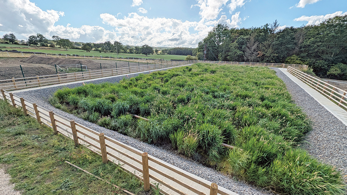
New aerated reed bed in service (August 2025) - Courtesy of MMB