Tideway Central – Blackfriars Bridge Foreshore (2021)
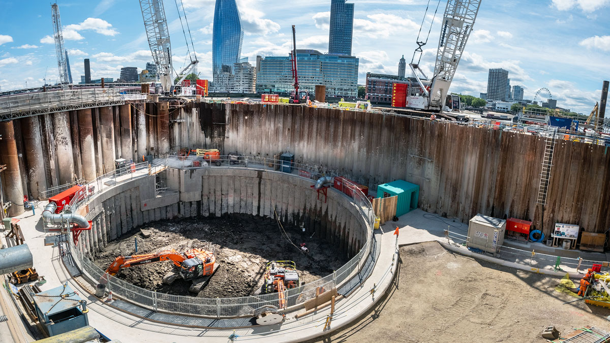
Construction of the shaft within the twin wall cofferdam in the River Thames - Courtesy of FLO JV/Tideway
The Tideway project is a new £3.8 billion, 25km long combined sewage storage and transfer system currently under construction in London. The project is divided into three design and build contracts: West, Central and East. The scope of works of the Central Section, the largest contract, includes 12.7km of 7.2m internal diameter tunnel and eight sites with deep drop shafts and ancillary structures. This article discusses the design and construction of the Blackfriars Bridge Foreshore CSO drop shaft, a 22m internal diameter and 52m deep shaft which is part of the Central Section. It will focus on the design of the shaft primary lining and the challenges faced, including developing a solution with a flexible construction sequence that was not dependent on the TBM programme, dealing with challenging ground conditions which have required dewatering and record-breaking jet grouting to allow programme-efficient piled and SCL methods to be used safely and successfully, and designing the secant piled section of the shaft to withstand significant hoop forces at 25m depth.
Background
London’s 150-year-old Victorian sewerage system was designed by Sir Joseph Bazalgette to serve a population of 4 million people. However, the population of London is currently 8.7 million and estimated to rise to 16 million by 2160 (Tideway, 2020). Consequently, millions of tonnes of excess untreated sewage and stormwater annually spills into the River Thames via the combined sewer overflows (CSOs), which direct excess flows into the River Thames to prevent flooding of streets and homes when it rains. This volume is increasing and is a great health risk to river users and the environment.
The Thames Tideway Tunnel, which is expected to be completed in 2024, will intercept, store, and convey the flows from the most polluting CSOs to protect the river for at least the next 100 years and create a cleaner and healthier environment.
Blackfriars Bridge Foreshore (BLABF)
The Blackfriars Bridge Foreshore site is located within the City of London. The main purpose of Blackfriars Bridge Foreshore shaft is to transfer, via two vortex drop tubes, the flows from the Fleet Main Sewer CSO and the weir on the Low Level Sewer into the main Tideway tunnel.
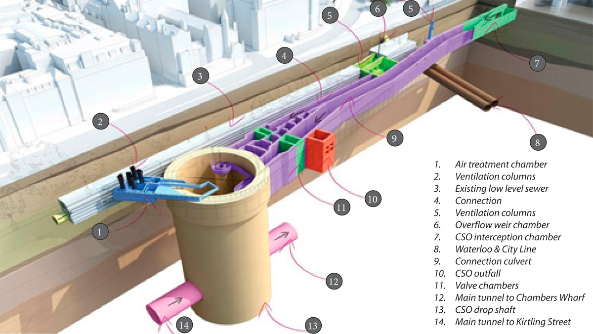
Scope of works at BLABF
The shaft is an on-line shaft which means the main tunnel passes directly through it. It was also the location for the main tunnel TBM, named Ursula, to undergo an essential intervention to prepare the cutter head prior to tunnelling through the Upnor Formation, Thanet Sands and chalk.
Primary support for the 52m deep shaft was achieved by secant piled wall for the upper 25m and sprayed concrete lining (SCL) for the lower section. These methods were chosen over the originally planned diaphragm wall method due to the limited space on site and to speed up construction as the shaft sits on the critical path for delivery of the project. It has a 4m thick reinforced concrete base slab, will have a 1m thick secondary lining, two vortex structures, a 2m thick shaft heading for ship impact and hybrid precast/in situ beams and slab for the roof structure. Due to the hydraulic requirements of the project, the final secondary lining of the shaft must have a minimum internal diameter (ID) of 22m.
The secant piled wall upper section of the shaft was constructed from a piling platform level of 96.5m ATD and founded in the London Clay at 71.5m ATD (25m length). The wall comprised 90 no. C40/50 (at 56 days) hard/hard secant piles with 1500mm diameter primary piles and 1300mm diameter secondary piles. The radius of the centreline of the wall is 12.9m. This geometry was governed by the minimum interlock required to achieve adequate bursting capacity of the wall.
The SCL lower section of the shaft was constructed from 71.5m ATD down to top of the base slab at 49.75m ATD. The SCL is 600mm thick C32/40 fibre reinforced concrete with a 75mm sacrificial layer.
A temporary twin wall cofferdam (six-celled) and intermediate cut-off wall were installed within the River Thames and drained to provide a safe working area for shaft excavation.
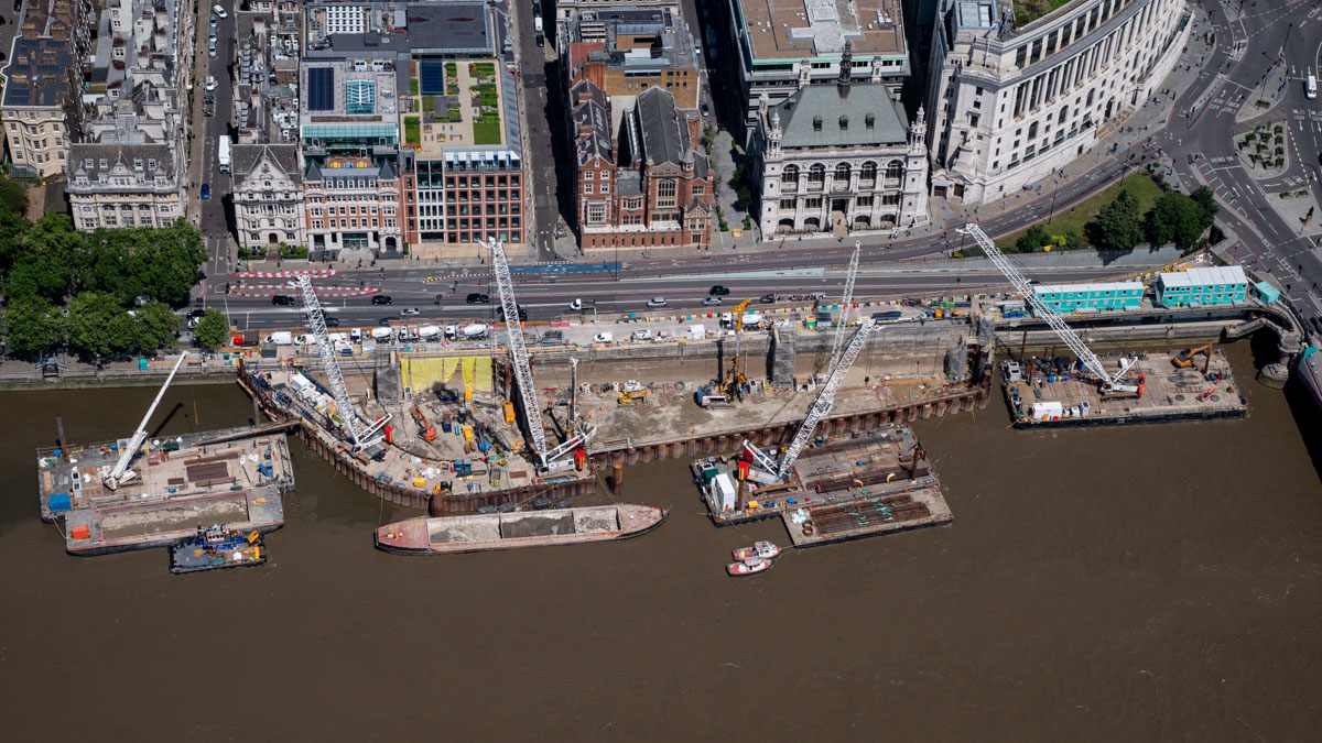
Aerial view of the site – Courtesy of FLO JV/Tideway
Tideway Central: Blackfriars Bridge Foreshore: Supply chain – key participants
- Client: Tideway
- Project manager/principal designer: Tideway (Jacobs)
- Principal contractor/lead designer: FLO JV
- Main designer (permanent works): AECOM
- Durability consultant: OTB Concrete
- CAT III checker: Arup Atkins JV
- Sub-consultants (temporary works): PERI
- Sub-consultants (temporary works): Hunnebeck
- Sub-consultants (temporary works): Laing O’Rourke
- Sub-consultants (temporary works): Robert West
- Sub-consultants (temporary works): Fairhurst
- Dewatering contractor: WJ Groundwater
- Piling contractor: Expanded Ltd
- Jet-grouting contractor: Keller UK
- Instrumentation & monitoring contractor: SELECT Plant
- Sprayed concrete: CEMEX
- Sprayed concrete: FLO JV
- Steel: Express Reinforcement
Challenging ground conditions
The shaft formation level is approximately 50m below the riverbed and passes through superficial deposits of alluvium and river terrace gravels followed by London Clay and the Lambeth Group with the formation within the Thanet Sand. The Lambeth Group, associated sand channels and Thanet Sand present a risk of confined aquifers under pressure that could lead to inundation and hydraulic failure of the ground, and the potential for ground collapse and excessive settlement when using SCL techniques.
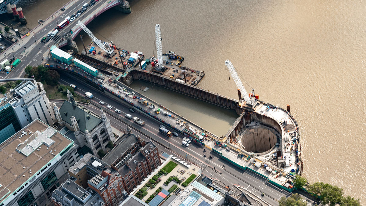
Aerial view of the site – Courtesy of FLO JV/Tideway
The use of SCL at this site was only possible by developing an extensive dewatering and depressurisation scheme. Dewatering of the intermediate aquifer (Lambeth Group and associated sand channels) and the lower aquifer (Thanet Sand and Chalk) was required during shaft excavation and SCL construction. The primary means of dewatering was via surface dewatering wells targeting the Lambeth Group sand channels and the lower aquifer. In addition to this, advanced probing of the Lambeth Group within the shaft was carried out to depressurise any pockets not intercepted by surface dewatering.
Additionally, to minimise the potential for ground collapse and excessive settlement when constructing the SCL, the excavated face was pre-supported using ground strengthening by means of a circular jet-grouted curtain, formed by a series of overlapping jet-grouted columns. The technique of jet grouting, which uses high pressure water jets to remove material and then mixes the remainder with cement-based grout to form columns, was employed following a successful full-scale trial at FLO’s main drive site (Kirtling Street Shaft) in which 2m diameter columns were achieved. Jet-grouting was carried out from the working platform at 96.5m ATD and is believed to be the UK’s deepest jet grouting, targeting the upper mottled beds sand channels of the Lambeth Group at 66m ATD, and the Upnor Formation and Thanet Sands down to 44.5m ATD.
Jet grouting was also used to form a grouted block above the TBM intervention location. On site, each column was surveyed, and a Monte Carlo analysis used to risk-assess the probability of gaps between columns so that additional columns could be installed as required.
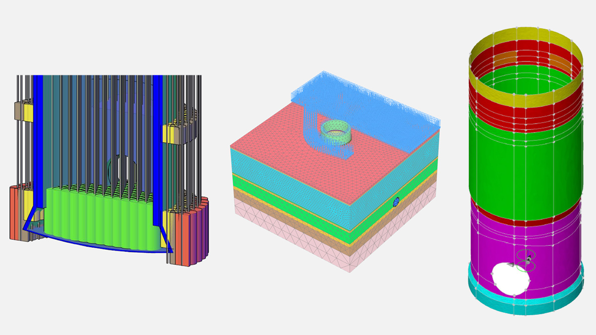
(left) Cross section of jet grouting scheme – Courtesy of Keller, (middle) PLAXIS numerical model and (right) LUSAS numerical model – Both courtesy of AECOM
Numerical analysis
Complex numerical analysis was carried out to support the shaft design and resulted in several design optimisations. Soil-structure interaction (SSI) analysis of the shaft was undertaken with 3D geotechnical finite element software PLAXIS. A 3D structural-shell model was also developed using finite element software LUSAS for validation and structural design purposes. The ground and groundwater pressures generated by the PLAXIS analysis were applied in 3D LUSAS analyses.
The SSI analysis simulates the excavation and spraying of each SCL ring step by step. It is modelled using the linear elastic material model with isotropic stiffness, which is updated to reflect its time-dependent behaviour according to Chang & Stille (1993).
The structural forces in the SCL are highly dependent on the excavation sequence and the stiffness of the SCL and therefore this method resulted in smaller structural forces and larger ground movements when compared to a less detailed analysis, e.g. assuming a 28-day stiffness in all construction stages. This produced reduced structural forces which are considered more realistic and lead to a more efficient and economic design.
Hoop forces at depth
One of the main challenges was to design the secant piled section of the shaft to withstand significant hoop forces at 25m depth when considering pile installation tolerances and the impact of follow-on SCL. Hoop forces are checked against the bursting capacity of the wall when considering worst case deviation of two adjacent piles due to an assumed 1H: 200V verticality and 25mm positioning tolerances.
The design hoop forces were calculated from the SSI analysis, in which the secant pile wall is modelled using linear elastic volume elements with isotropic stiffness. An upper and lower bound hoop stiffness is considered for the secant piled wall, with the upper bound based on isotropic behaviour and the lower bound based on orthotropic behaviour to represent joints between the piles and vertical deviation of individual piles (Zdravkovic et al., 2005).
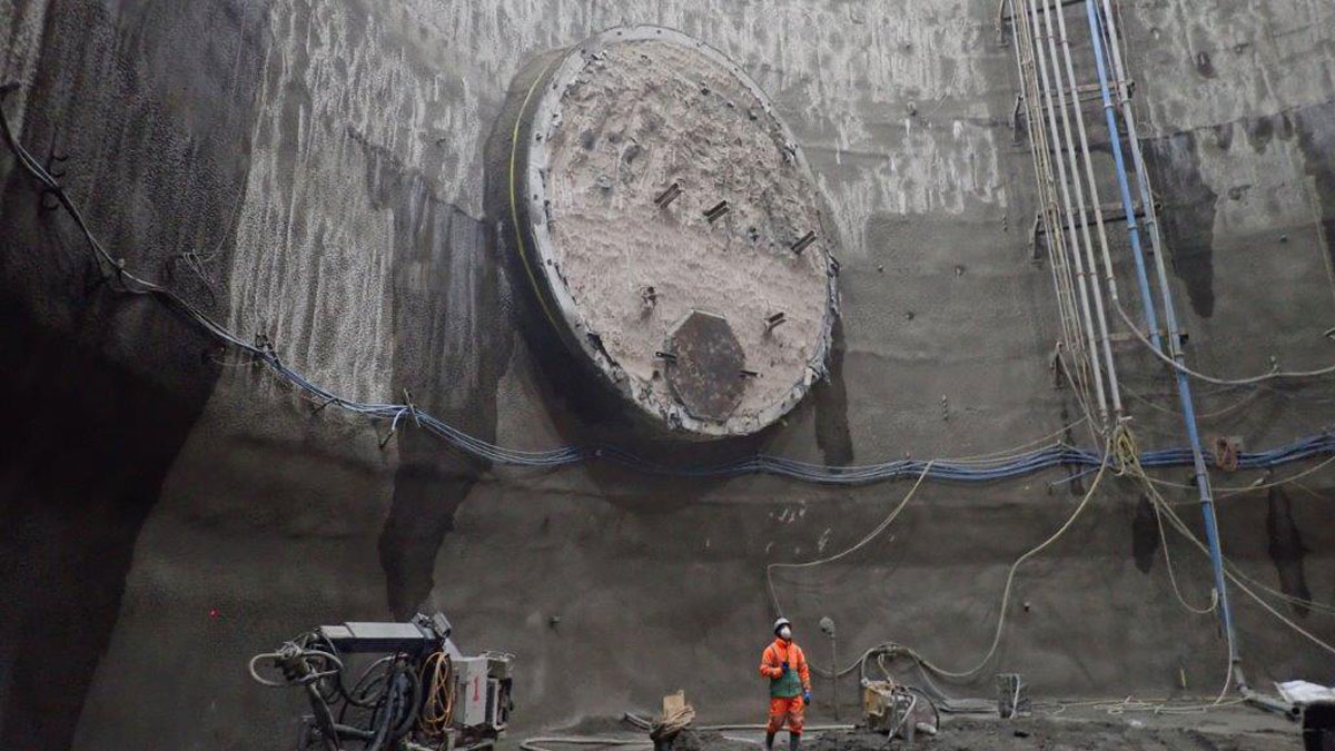
Exposed foam concrete in main tunnel and tapered base slab excavation – Courtesy of FLO JV/Tideway
The upper bound stiffness yields the most onerous hoop force whereas the lower bound stiffness yields the maximum pile and ground movements.
Follow-on SCL initially generated large additional hoop force in the bottom few metres of the SCL due to arching of the soil. This behaviour was found to be heavily dependent on the SCL excavation and construction sequence and the properties of the joint between the SCL and the piles, and hence its ability to transfer hoop forces in the SCL.
By modelling the joint as a ‘rough’ interface as opposed to the conservative assumption of a ‘fixed’ connection, and considering a coefficient of lateral earth pressure, Ko, of 1.0 for the London Clay to account for the effects of secant pile installation, the design hoop force was reduced. These modelling optimisations resulted in design hoop forces that were not overly conservative and within the bursting capacity of the secant piled wall, leading to a more efficient and economic design.
Programme challenges
One of the biggest challenges was to develop a solution to enable the construction of the shaft independent of the main tunnel construction, in order to avoid any impact on the shaft or main tunnel programme which could in turn impact delivery of Tideway.
This required the development of a construction methodology that allowed construction of the shaft either before or after the main tunnel had been constructed.
Two different options were designed and simulated in the SSI analysis to accommodate this, in which the main tunnel segmental primary lining was represented by linear elastic two-dimensional plate elements with axial, shear and flexural resistances.
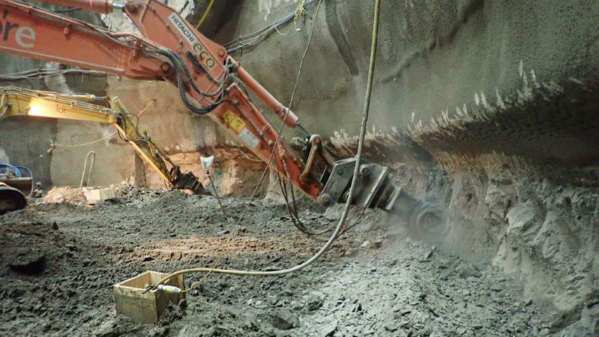
Excavation of the SCL section of shaft – Courtesy of FLO JV/Tideway
The first option considered the TBM passing prior to construction of the shaft SCL section and this is the option that was constructed. Results of the analysis indicated that the impact on the secant piled section of the shaft was small and acceptable. However, it also indicated that excavation of the SCL section of the shaft would have an impact on the displacements and stresses within the main tunnel lining.
As a result, traditional bar-reinforced segments for the main tunnel were installed for 7 (No.) rings either side of the shaft, in addition to foam concrete support inside the tunnel for 3 (No.) rings either side of the shaft and 2 (No.) rings inside the shaft. The analysis determined that this was required to be implemented prior to shaft excavation below 66m ATD to avoid compromising the dowels between main tunnel segments.
The SCL section of the shaft was then formed around the main tunnel, which was broken out within the shaft footprint. Due to the risk of instability during undermining of the main tunnel segments, it was initially expected that this excavation would be carried out in pockets to limit loss of support.
However, upon further analysis, it was found that the shaft could be excavated in halves for the entire depth of the SCL, saving time and costs. The secondary lining will then form the thickening at the portals which is required to transfer stresses around the tunnel openings once the foam concrete support inside the main tunnel lining is removed.
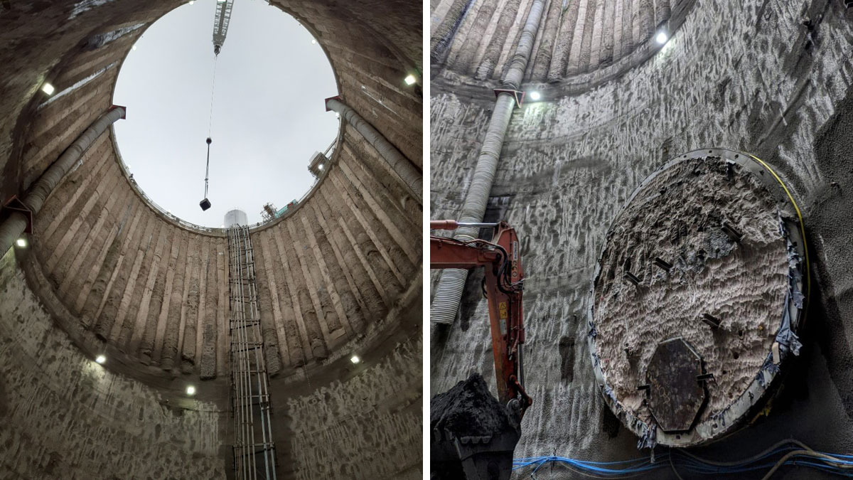
(left) Secant piled and SCL shaft primary lining and (right) Exposed foam concrete in main tunnel following breakout of tunnel within shaft – Courtesy of FLO JV/Tideway
The second option considered the TBM transit occurring after construction of the shaft, but this was never constructed. The design kept the main structural elements of the shaft as similar as possible to the first option for flexibility, e.g. the thickening at the portals of the tunnel eye, which would be required to withstand significant hoop stresses generated during breakthrough, would again be formed by the secondary lining.
Conclusions
At the time of writing (July 2021), the shaft primary lining has been constructed successfully and the scheme is expected to be completed by 2024.


