
Rosebery WTW (2021)
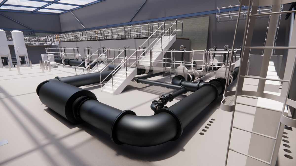
Model visualisation of the inlet pipework with the roof omitted - Courtesy of ESD
Located in Temple, near Gorebridge, in Midlothian, Scotland, Rosebery WTW treats raw water sourced from Megget and Gladhouse Reservoirs which is blended at the works inlet. The blended raw water is generally low in turbidity (2.0 NTU 95%ile), moderate colour (63 mg/l Pt/Co 95%ile), with average to high metals concentrations (55 to 300ug/l Mn, Al, Fe). In recent years, Rosebery WTW had suffered a number of water quality incidents, including positive detections of cryptosporidium and so Scottish Water sanctioned the £15.5m project to address water quality issues, with ESD, their non-infrastructure alliance partner, beginning design work in 2017.
Existing works
Blended raw water is dosed with polyaluminum chloride (PACl – Alba18). The coagulated water passes through a mixing chamber before parallel distribution to three dissolved air flotation (DAF) tanks. The three DAFs were retrofitted with Purac’s DAF Rapide™ system prior to 2009.
Clarified water then gravitates to eight dual media rapid gravity filters (two banks of four filters). The filters were originally single sand media, but were upgraded recently by ESD to dual media to prolong filter run times. The filtered water is blended in the filtered water channel, before dosing with orthophosphoric acid for plumbosolvency and disinfected with chlorine gas. The treated water then passes into the chlorine contact tank and the pH is stabilised with the addition of lime (Ca(OH)2) (recently upgraded to sodium hydroxide, NaOH). The final treated water gravitates to two clear water storage tanks for final water storage (9,000m3 and 13,000m3 capacity respectively).
Sludge from the DAFs is combined with the dirty filter backwash water in a series of four balancing tanks, operated in parallel. The blended sludge/washwater is dosed with polyelectrolyte and pumped to two WRc type thickeners, which operate in either a duty/standby or duty/duty configuration. Supernatant from the thickeners is balanced in a sump prior to pumping back to the head of the works. The thickened sludge is pumped to two plate frame filter presses for dewatering and the cake stored in skips prior to removal from site to landfill.
Inlet building model – Courtesy of ESD
Project need
Scottish Water identified improvement measures to address the performance of the works. A Root Cause Analysis report was prepared that noted several factors with the potential to reduce the reliability of the works, and detrimentally affect the ability to provide a robust barrier to cryptosporidium breakthrough. The main issues reported were:
- Ineffective flocculation at the front end of the treatment works (mixing chamber, flocculators) for the current hydraulic loading.
- Undersized and overloaded DAF process leading to inefficient clarification.
- Poor control over the front-end water chemistry (with specific reference to coagulant control) with oversized coagulant dosing pumps and lack of flocculant dosing.
- Poor quality (high turbidity) supernatant return from the underperforming washwater/sludge treatment process with the associated risk of cryptosporidium oocysts return.
Inlet building at pipe gallery – Courtesy of ESD
Project scope
Following an in-house optioneering process to address the issues, Scottish Water identified that the following works should be undertaken by ESD:
Increase capacity to provide a deployable output of 40 MLD
- Undertake modifications to the raw water inlet mains by diverting to the new pre-flocculation chamber.
- Provide a new pre-flocculation chamber and flow split chamber.
- Provide a new polymer dosing facility to improve DAF performance.
- Provide a new PACl dosing facility.
- Provide two additional DAFs to reduce hydraulic loading on the existing DAFs.
- Provide a new inlet building to house the new pre-flocculation chamber, flow split chamber and DAFs.
- Provide a new MCC for the new DAFs, chemical dosing and associated plant and equipment.
Hydraulic improvements through the treatment process
- Resolve the uneven flow split to the existing DAFs.
- Resolve the uneven flow split to the existing RGFs.
Washwater and sludge treatment improvements
- Provide a run to waste facility and flow monitoring for the RGFs and install flow monitoring to the RGFs.
- Convert the existing sludge/washwater tanks to filter run to waste and backwash washwater holding tanks.
- Provide a new DAF sludge balancing tank and sludge pumping station.
- Provide a new lamella settler and polymer dosing system for washwater settlement.
- Provide a new supernatant return pumping station.
- Provide a new MCC for the new washwater and sludge plant and equipment.
Control system upgrades
- Upgrade site wide SCADA, PLC, network and telemetry.
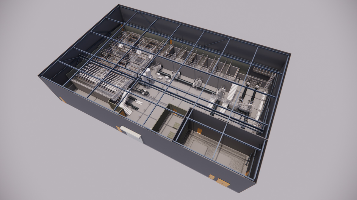
Visualisation with the roof omitted – Courtesy of ESD
Key project constraints
The existing Rosebery site is extremely constrained by existing assets and topography and this was exacerbated by the need to maintain operation at full output throughout the construction and commissioning phases. This limited the options available for the siting of the new DAF plant and washwater/sludge recovery plant.
Interfacing the new works with the existing plant was problematic, with the selected location of the new inlet works and DAF plant limiting the available routes for interconnecting pipework and ducting, as well as posing process challenges for floc stability between the new and existing treatment buildings. This, combined with the presence of a large number of existing services on site presented further challenges for the design and construction team.
The existing works can only be shut down for a maximum period of four hours, so this has presented significant challenges in the planning and sequencing of the construction and commissioning work, in particular with the interface connections.
Digital delivery benefits
ESD applied digital design tools to mitigate the risks and constraints that had been identified. A model of the existing site was generated in Civil 3D using 3D topography for the building and ground profile, and GPR data to locate existing services. Clash detection was undertaken to identify any diversion needs and to develop safe working corridors for the principal pipe and duct routes. This approach highlighted that the original principal pipeline routes were congested with existing services and a safer, alternative route some 20m further south should be utilised. The digital design also identified that the existing HV site incomer required diversion and early engagement with SP Energy Networks allowed this work to be carried out ahead of the planned construction works.
Inlet building front elevation – Courtesy of ESD
All new pipelines were designed and generated in Civil 3D with real time updates to the plan and long section outputs. Once the new proposed pipelines were in the model, clash detection was run against existing and other proposed pipes for each new pipeline. The routes and invert levels were easily adjusted and optimised, with greater accuracy and efficiency when compared to a traditional 2D approach.
The new inlet building, housing the incoming raw water valves, chemical storage and dosing, pre-flocculation tanks, flow splitter chamber, two DAF streams and associated ancillary equipment, and MCC, was designed and created in Autodesk Revit. Once the views for the drawings sheets were set up, any changes made to the model automatically updated on the drawings, minimising re-work. Weekly virtual collaboration sessions to review the model and coordinate the civil, mechanical and electrical interfaces were key to managing interfaces for a successful model output.
Ross-shire Engineering provided 3D models for the chemical dosing, storage and delivery areas, which ESD integrated into the main federated model. The opportunity for the ESD design and construction team and key suppliers to visualise the design in 3D, permitted early identification and swift resolution of interface issues. The digital design process aided ESD to reduce the building footprint by 130m2 during detailed design.
The new inlet building is set into the existing hillside and there is a rise from existing road level to the floor level. The earthworks around the new inlet building, and the chemical delivery in front of the new inlet building were designed in Civil 3D using rule sets on gradients to determine the required levels.
Optimising the earthworks in Civil 3D reduced the extent of retaining wall required from outline design and achieved a 110m3 saving in concrete volume.
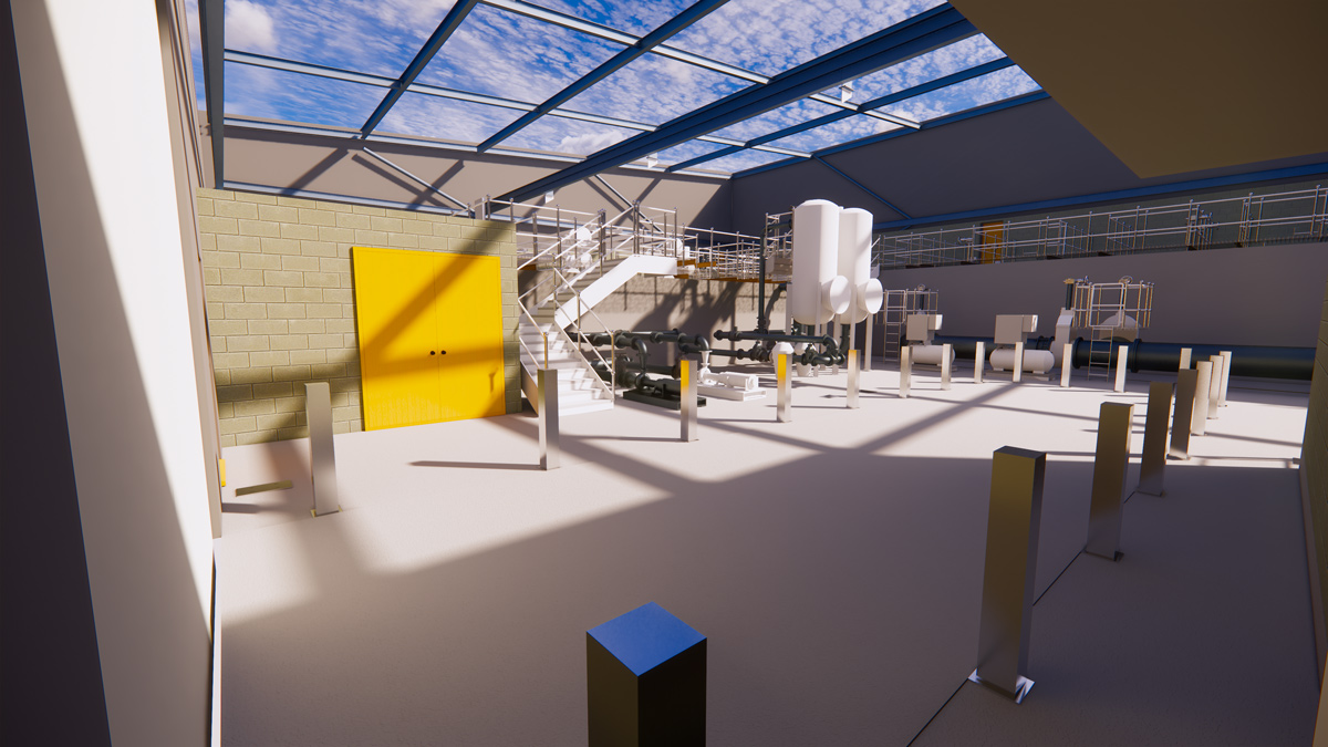
Model visualisation of the DAF plant with the roof omitted – Courtesy of ESD
ALM improvements and value engineering
Using previous design experience from Glencorse WTW as inspiration, ESD relocated the control valves into the new inlet building and removed the external valve chamber that was proposed in the initial design stages.
The reuse of the Glencorse design replicated a proven solution that the local Scottish Water Operations team are familiar with, eliminated a confined space, and provided improved, safer operation and maintenance of the plant.
The ALM strategy for the new inlet building was developed using the model, and the Client HAZOP2 was worked through using the federated Civil 3D/Revit model in NavisWorks, together with a virtual walk through. This gave the Operators a better understanding of their new asset and allowed them to provide valuable feedback for optimisation of the final design. Working with Scottish Water, ESD were able to create a design with which operational staff were happy to proceed.
Hydraulic optimisation
The original design solution required a new 120m long 800mm diameter overflow pipe from the new inlet building to the existing overflow pipe. During the hydraulic design process ESD were able to remove this from the scope by identifying that it was possible to hydraulically connect the new inlet building to the existing overflow via the existing process stream without the need for the overflow pipe.
As part of the hydraulic design, ESD assessed the velocities throughout the plant. This identified that the inlet pipework design could be optimised by reducing the pipe diameter of the connection pipes from the Megget and Gladhouse mains from 700mm to 500mm over the 150m length whilst still meeting Scottish Water’s specification.
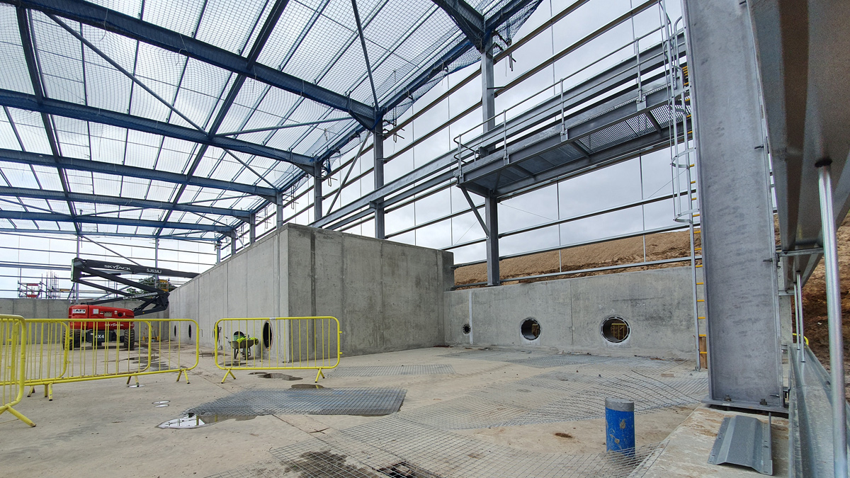
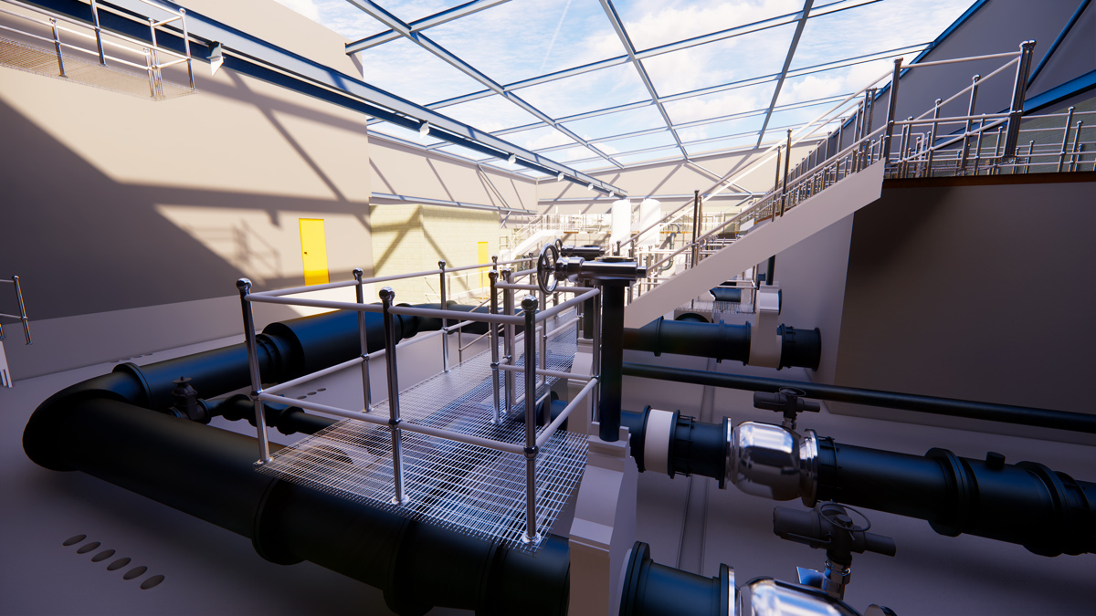
Pipe gallery area – Courtesy of ESD
Carbon saving
Using Scottish Water’s Capital Carbon Accounting Tool, ESD were able to demonstrate that the design optimisation from innovative use of digital delivery tools and clever hydraulic design achieved the following embodied carbon savings:
- Removing external valve chamber: 27,482kg CO2e
- Reducing building footprint: 27,822kg CO2e
- Reduce retaining wall requirements: 33,402kg CO2e
- Removing overflow: 49,690kg CO2e
- Reducing inlet pipe diameter: 13,188kg CO2e
- Total embodied carbon reduction: 151,584kg CO2e
To put the saving into context, it is roughly equivalent to the amount of CO2 that could be removed from the atmosphere by planting 75,000 trees (based on a Forestry Commission study that calculated a tree can store 2kg of CO2).
Rosebery WTW: Supply chain – key participants
- Main contractor & design: ESD
- Chemical dosing: Ross-shire Engineering Ltd
- Inlet building civils: PJ Carey
- Mechanical installation: Homer Burgess
- Electrical installation: ICL
- MCC & SCADA: Saftronics
- MCC trench: Cubis Systems
- Overhead crane: Kone Cranes
- Sludge balancing tank: Goodwin Tanks
- Access steelwork: HK Gillies
- Lamella: Jacopa
- Ventilation: Wright Air Systems
- Telemetry: Boultings
- Kiosks: Quinshield
- Potable water booster set: KGN
- DAF scrapers: EPS Water
- Penstocks: Industrial Valves
- Instrumentation: IDS
- Valves: AVK
- Static mixer: Statiflo International
- Pumps – sludge feed: Vogelsang
- Pumps – DAF: Celeros
- Basket strainers: Oxford Filtration
- Compressor & saturators: MB Air Systems
- Flow meters: Process Plus
- Lifting equipment: Reid Lifting
- Prefloc mixers: NOV Process and Flow Technologies
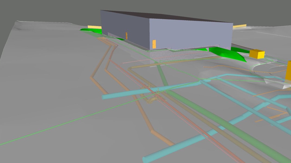
Federated model showing 3D pipe network – Courtesy of ESD
SCADA, PLC, network and telemetry upgrade
A control system upgrade for the entire works was required. The existing RS View 32 SCADA terminal was not only obsolete but was unable to record water quality data on site. ESD engaged with a framework system integrator to replace the existing SCADA terminal with a framework and specification compliant SCADA system, consisting of two Siemens SIMATIC SCADA WINCC workstations and ancillary equipment located in the main control room. The SCADA system was configured with redundant servers and communicates on a fibre network to the existing control system.
The migration of the SCADA system had to be carefully planned and a detailed migration plan was developed. ESD worked with site operations and key stakeholders to identify migration risk, including loss of control and supervision of critical process plant, with a focus on minimising any disruption. The migration plan proposed that each PLC should be migrated from the old SCADA to the new using a gateway interface panel to support a seamless transition. The interface panel acted as a direct gateway device between an existing Rockwell Data-Gatherer PLC and the new WinCC SCADA. The Data Gatherer PLCs purpose was to collate SCADA and telemetry I/O from a number of PLCs across the site. Comprehensive factory acceptance testing using a detailed and approved SCADA functional design specification was undertaken prior to start on site.
The existing telemetry Regin Type 2 outstation was also replaced with a new telemetry outstation; a framework compliant Xylem ATU900 communicating on Modbus to the Data Gatherer PLC.
MCC trench – DfMA and programme savings
ESD identified an opportunity for programme savings by utilising a Cubis MCC trench for the bottom entry sludge MCC. The trench is a DfMA structural walled plastic MCC trench constructed in the factory and delivered to site on the back of a lorry complete with the internal support steelwork and the durbar floor plates.
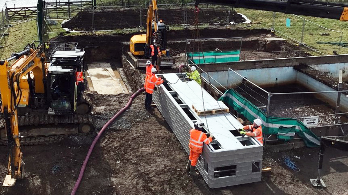
MCC trench from Cubis Systems – Courtesy of ESD
Site preparation for the Cubis Systems trench included excavation to formation level with a simple base slab for the trench to land on. The trench was delivered to site then off-loaded and landed into place the same day. Once landed, the excavation was backfilled around the trench and then a ground bearing slab laid level with the top of the trench for the MCC kiosk to sit on. This saved an estimated seven days versus traditional reinforced concrete construction methods and reduced H&S risks.
Commencement of works on site
To support design and construction, the following advanced works were completed by ESD in collaboration with Scottish Water:
- GPRS and utilities trial pitting.
- Topographical survey.
- Ground investigation including boreholes and trial pits.
- Discussions with SP Energy Networks for relocation of the HV cable.
- Landowner liaison for land purchase and temporary rental.
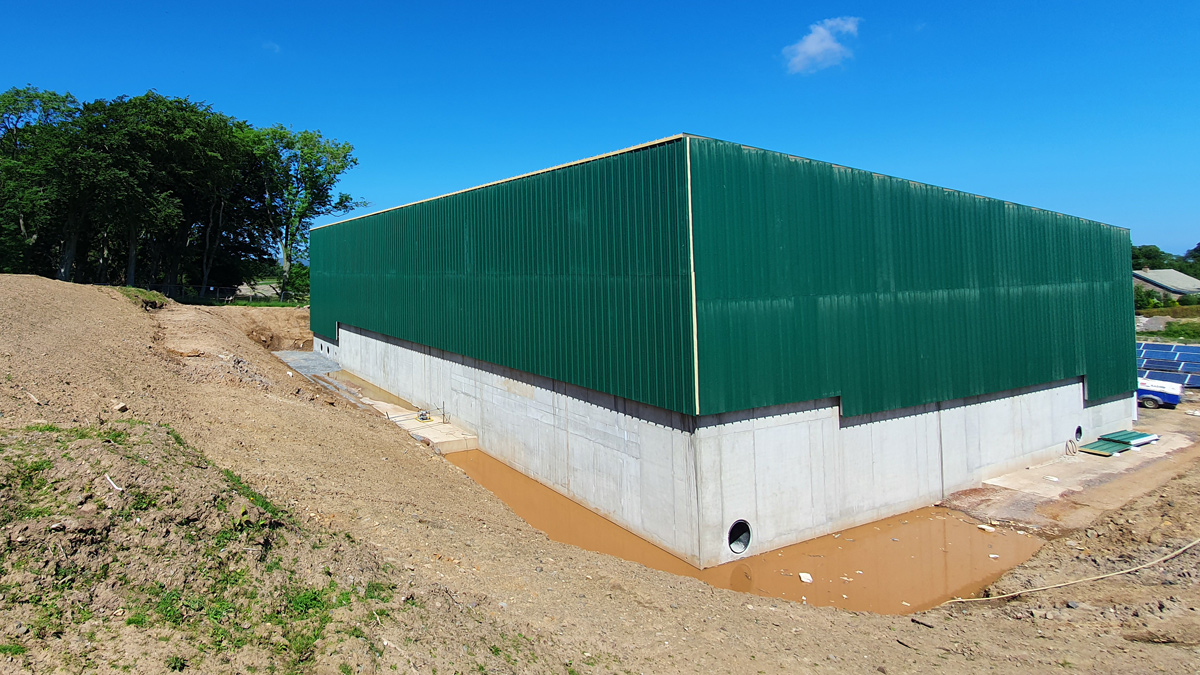
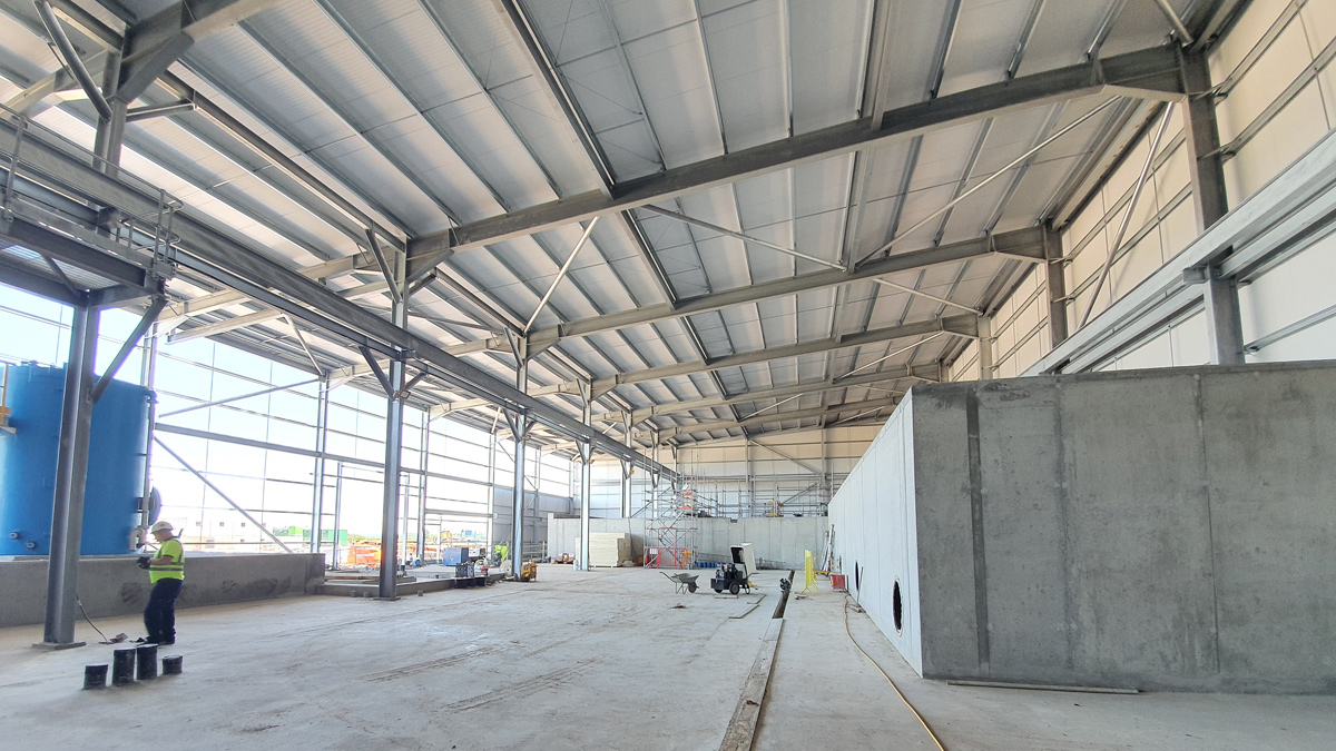
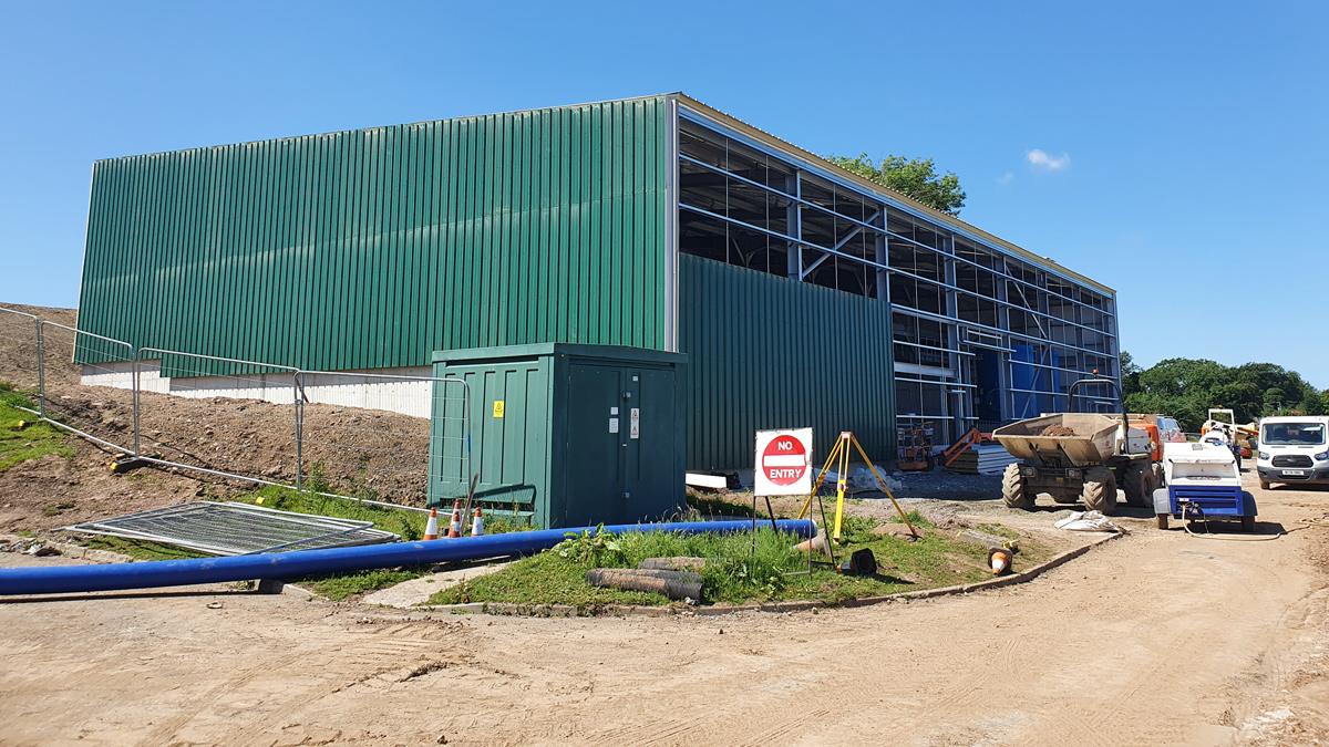
Inlet building – south east corner – Courtesy of ESD
ESD started on site on 9 November 2020 and at the time of writing (July 2021), the main substructure and superstructure works for the inlet building have been completed, with internal works commencing August 2021.