Tideway Central – Watertightness Testing (2021)
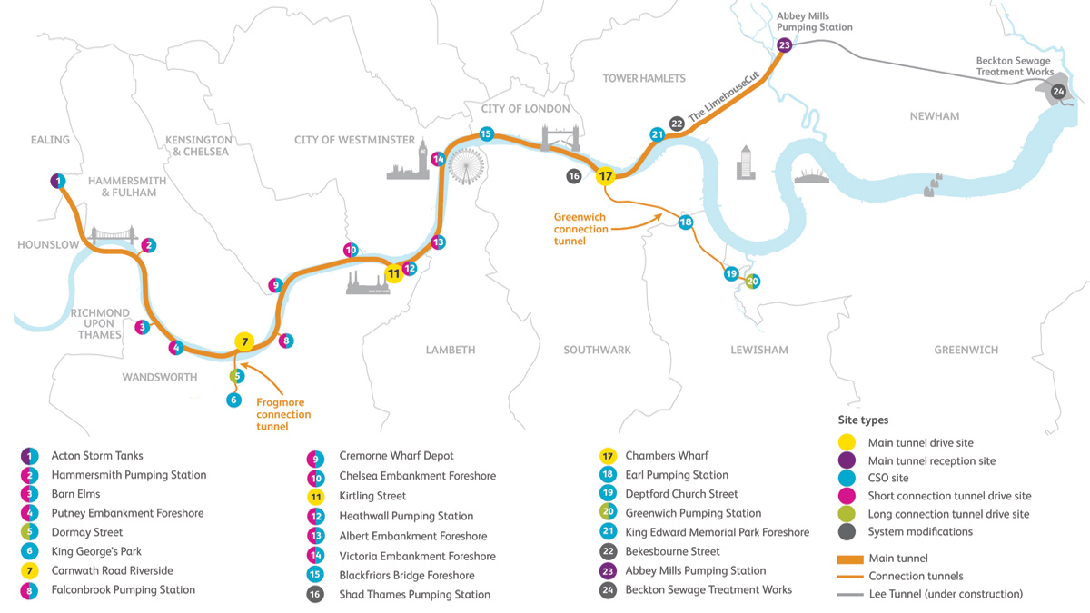
The Thames Tideway Tunnel route and sites - Courtesy of Tideway
The Thames Tideway Project is a major infrastructure project that will intercept the existing London sewerage system through a series of tunnels running 25km from Acton in West London to Abbey Mills in East London. There are 22 vortex drop pipe structures and other near surface structures that will intercept existing spills into the Thames; transporting the discharged effluent into the newly constructed tunnels. A key requirement of the Tideway Project is that the near surface, below-ground structures are required to comply with Clause 7.14 of the Civil Engineering Specification for the Water Industry 7th Edition (CESWI7). This requires testing of the concrete structures designed to retain an aqueous liquid by means of a water filled drop test.
Background
In Clause 7.14, items 1 and 2 refer to testing before backfilling and sealing any visible leakage on the outside of the structures, implying that the testing is intended for cut and cover or above-ground water retaining structures. Generally, such installations have ready access to external faces for inspection during testing so that the source of any potential problems can be identified. Most, if not all chambers on the Tideway project are cast against supporting primary structures such as secant piled walls where inspection of the external surface would not be possible. The below ground structures, up to 18m deep, also intercept the existing sewer network with layouts that make isolation for testing difficult. Therefore, the difficulties in identifying problems where a structure could not pass a test meant that an alternative testing approach was sought.
Although the structures are properly designed and constructed, faults could occur so the objective of the water test is to find and correct any faults before the structure is put into service. A concern of the operator, Thames Water Utilities Ltd (TWUL), was the risk of contamination of the aquifers and surrounding ground arising from leakage of the contents of the Tideway structures, so successful testing was crucial for acceptance. The main purpose of the alternative approach was to ensure that all possible steps were taken to prevent pollution of the surrounding ground by properly demonstrating that the water tightness of the structures satisfies the expected performance intended in Clause 7.14.
An alternative approach was developed by the project’s Main Works Contractors (MWCs), in agreement with Tideway and TWUL, which had to demonstrate the same, or greater, level of assurance to the regulatory bodies in the proposed testing regime demonstrating watertightness.
Drop-head test – CESWI
The CESWI7 test is a full-scale performance test of the structure in the condition which it may occasionally be subjected to. This is costly, time consuming, does not always allow the leak to be located, and is potentially impractical due to the interface with the existing sewer network.
The pass/fail criteria given in Clause 7.14 is a reduction in water level from the test level by the lesser of 10mm or 1/500th of the depth. To be able to use the 1/500th criterion, the depth must be less than 5m. The origins of these criteria are historical and unknown, but they are generally accepted in the water industry for application in service reservoirs and similar structures.
In addition to the difficulty of being able to identify any leaks, sealing outlets and creating compartments is not easy:
- The layout of the CSO sites means it was not possible to fully water test the interception structure without closing the connecting storm sewer. This is impractical for the time needed for testing and even for short periods could lead to upstream sewage flooding or overflowing into the river.
- Means of isolating compartments of the structure with pressures of up to 180kN/m2 (18m depth of water) is extremely challenging with the following constraints considered for temporary bulkhead structures and method.
- Designed not to move when loaded.
- Designed to limit leakage.
- Construction requiring manual lifting in confined spaces.
- Potential impact to the permanent works from significant bulkhead fixings.
- Access challenges to measure bulkhead and penstock leakages.
- Safety concerns from flood risk.
- A sustainable source of water to carry out the test.
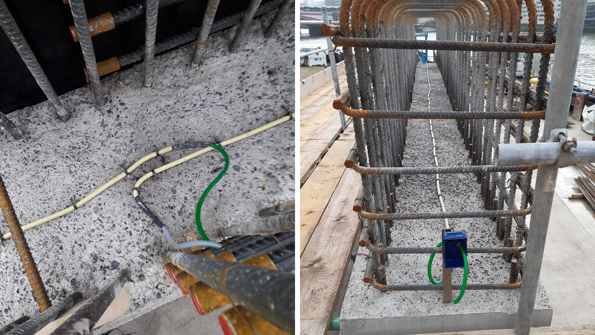
Blackfriars test panel: November 2019 – Courtesy of FLO JV
Tideway Tunnel Watertightness: Supply chain – key participants
- Main works contractors (MWCs)
- West: BAM Nuttall, Morgan Sindall & Balfour Beatty
- Central: Ferrovial Construction & Laing O’Rourke
- East: Costain, VINCI Construction Grands Projets & Bachy Soletanche
- Designer: Arup Atkins Joint Venture
- Reinjectable SikaFuko® tubes: SIKA
- Alternative watertightness testing: CK Tech Ltd
- Trials & data gathering: Praeter Engineering Ltd
Proposed alternative testing
The alternative testing approach challenged the industry accepted method of demonstrating water tightness from simple product performance, to an approach using a focussed element test, based on a risk assessment of the causes of water leakage.
Initially, an experience-based review was carried out of the most likely causes of leakage from the structures, which primarily related to construction joints and panel cracking. This review identified the construction joints as a detail that would most likely cause a test fail. Faults within panels are less likely to occur because there was a lower risk of problem-causing features and if present are easier to spot. Cracks were limited by design (water tightness class 1 to EC1992-3) and a highly specified quality control of concrete mixes and placement workmanship reduced this risk. Other inspection processes were put in place to address any anomalies.
The alternative approach therefore considered that if all the construction joints subject to operational water pressure were shown not to be a source of leakage above an allowable leakage rate then the risk of the whole structure leaking unacceptably would be negligible, to a level of risk that is acceptable. The approach focused on specific testing of the construction joints to prove their water tightness.
The use of re-injectable grout tubes is a well-established system, used worldwide, to seal potential leaks in construction and connection joints in watertight concrete structures that need a degree of water tightness such as tunnels, basements, car parks etc. The MWC’s considered that re-injectable tubes could be used to water test construction joints from the inside to out by injecting water to a known pressure and demonstrating that there is no leakage across the joint. That would allow each joint to be water tested to a known pressure and, if necessary, have polyacrylic resin injected to tighten and seal the joint if it is considered a fault. Follow-up water testing after resin injection could be carried out to prove the joint is sealed.
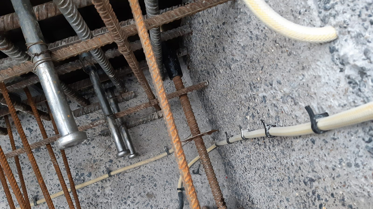
Typical arrangement of tubes – Courtesy of FLO JV
For the development of this approach the MWCs opted to use the SikaFuko® VT1 re-injectable hose system. Construction joints are generally concrete against concrete, and in some cases, joints were protected by an external waterbar and hydrophilic strips.
The proposed system comprises re-injectable tubes that were fixed to the surface in the middle of the section of the first pour at each construction joint. Tubes up to 12m in length are positioned so that both ends are accessible in an openable junction box that is cast into the concrete surface.
A pump can be attached to one end, whilst initially the other end is open to show that water, or later resin, being pumped through is filling the tube and demonstrate that the tube is not blocked. Injection of test water or polyacrylic resin is achieved by temporarily sealing the outlet end. The injectable section lies in the middle of the joint and under pressure the valves in the injectable section will open allowing the fluid into the joint. The valves in the re-injectable tubes are designed to open at about 1 bar pressure.
Trials
Various trials were undertaken at different sites including the West Drayton logistics facility, Deptford Church Street site and Blackfriars Bridge Foreshore site. Initially the tests were to prove that the proposed methodology was feasible and demonstrate it works on a series of joints. This included a poor defective joint to demonstrate the test would identify any defect, so that a follow up resin injection could be used to demonstrate the defect could be rectified and then retested with a water test.
These initial trails identified that even on well prepared joints carried out in very controlled conditions there would be loss of water pressure under test, even with negligible egress of water visible. Therefore, further research was carried out to understand the relationship between pressure loss and volume loss during the water test.
Tests were carried out using sensitive weight and pressure gauges (see the photo below) over a series of different periods, on different structures and joint lengths, to establish enough data for analysis.
The trials have provided evidence for the correlation between pressure loss and water loss in the hose system for joints able to withstand 2 bar of water pressure. They also showed that a 15‐minute water pressure test does provide a result that correlates well to a test carried out over a longer period greater than two-hours. The trials established that the test hose system is sensitive to pressure changes relating to very small amounts of water loss that are not attributed to seepage through the joint under pressure.
The data was also compared to the equivalent loss acceptable under the 7-day Clause 7.14 CESWI test for a typical structure and an acceptance criteria established with a suitable surplus factor. The test does not take into consideration the potential effects of autogenous healing during the CESWI test process that gives further confidence to the criteria.
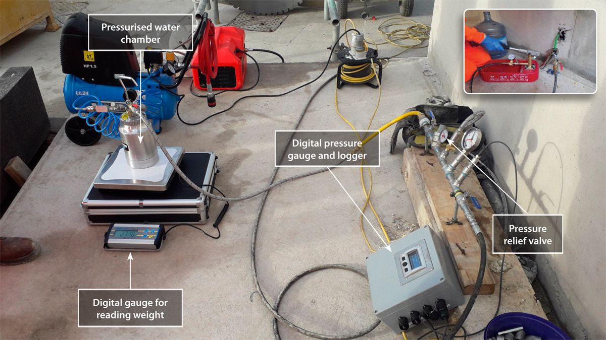
Trial testing equipment set-up and (inset) simplified on-site watertightness testing arrangement – Courtesy of FLO JV
This analysis and learning from the methods used in the trail established the following process and acceptance criteria to demonstrate a watertight construction joint.
- A 1‐hour constant pressure (at 2.0‐2.3 bar) wetting period undertaken immediately before each test (including any re‐tests).
- The start test pressure in all cases should be within the range 2.0 to 2.3 bar.
- A test pass is one where there is no greater than 0.5 bar pressure loss in a 15‐minute test window.
The trials also identified other learning that was taken forward into the methods and procedure including:
- Care needed in installation of tubes and surface connection hoses to ensure fully sealed injection points.
- Care needed on resin preparation for gel time setting and vacuum cleaning methods to ensure tubes are re-usable.
Following the trials to establish the method and process there was refinement of the tools, equipment and testing sequence to be used in the field on various underground structures.
The highly sensitive and delicate instruments needed for the research and development could not be used for day to day testing, so a simpler hand pump was selected to measure the pressure loss, reducing the amount of equipment required to perform the test.
Alternative approach test method
The testing of the construction joint would be a staged approach. The sequence is given in the flow charts below. The testing set up such as arrangements of the tubes were unique to each structure within the allowable maximum length.
The test method:
- A nominal one-hour wetting period where the hose is maintained at a pressure between 2 and 2.3 bar. This stage is to saturate the concrete local to the hose.
- A 15-minute water test period where the starting pressure is between 2 and 2.3 bar.
- At end of the 15-minute test period the finishing pressure will be recorded.
- If the difference between the starting and finishing pressure is less than 0.5 bar, the test criteria will be recorded as successful and the joint will have passed the test.
- If the difference between the starting pressure and finishing pressure is greater than 0.5 bar, the repair process of injecting polyacrylic resin will be carried out and the tube subsequently cleared of resin using water and vacuum pump.
- After a minimum of 12 hours to allow proper gelling of the resin, the tube will be filled with water to verify no blockage.
- A repeat of the 15-minute water test period and attainment or otherwise of the test criteria above.
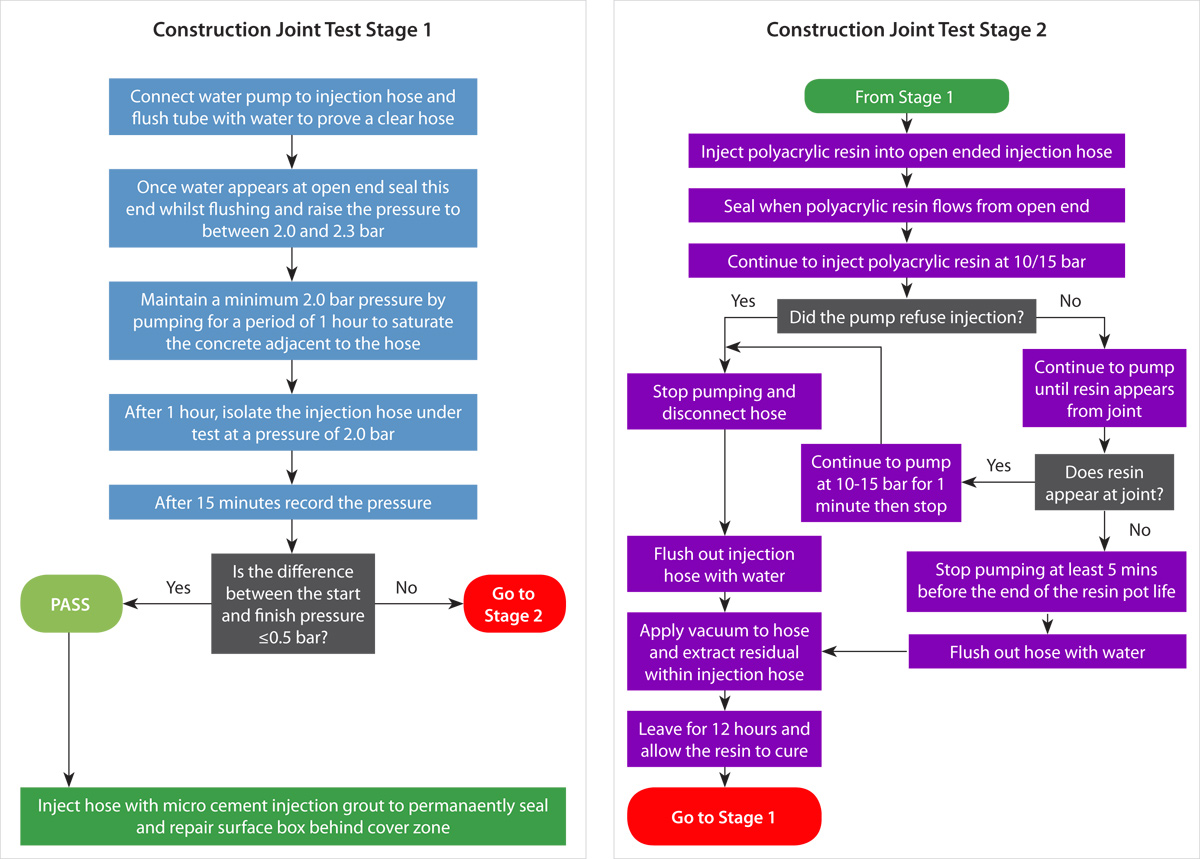
Sequence for testing of the construction joint – Courtesy of FLO JV
Conclusion
The development of an alternative testing approach by the MWCs on Tideway established a new method for water testing which has been successfully implemented to demonstrate the watertightness of structures. This method was compared against the watertightness requirements set out in CESWI7 Clause 7.14.to provide an equal or greater level of assurance. This development has brought benefit to the client and contractor with less disruption to existing sewer networks, less transport and disposal of test water, more flexibility to test complex locations as work progresses and making leaks easier to locate and seal.


