Hull WwTW (2020)
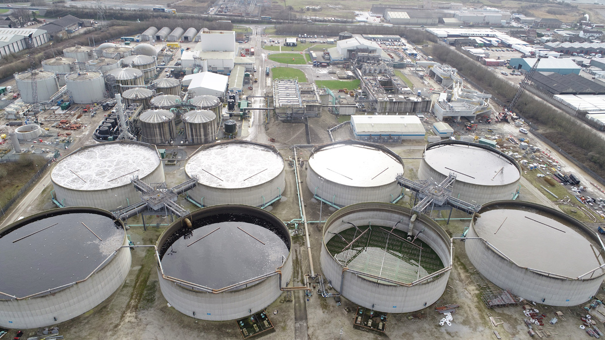
View of Hull WwTW - courtesy of MMB
Hull WwTW located at Saltend, east of Hull, provides sewage treatment for a population equivalent of over 1 million people, covering an area from the west of Hull to Hedon in the east. The existing treatment works was built over 20 years ago and required some specific upgrading and refurbishment. The primary drivers for the upgrade were:
- Improving preliminary treatment with a dedicated flow to full treatment inlet works.
- Improving sludge production for composting requiring the full M&E refurbishment of the digestion process, including new centrifuge dewatering facility.
- Improving the liquid and cake import facilities.
The solution
Yorkshire Water’s £34m scheme required the detailed design and construction of a new elevated inlet works for the preliminary treatment of raw sewage flow to full treatment of 2000 l/s and refurbishment of the existing sludge treatment facility.
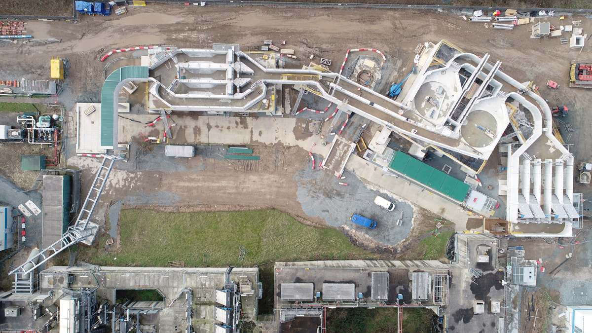
The new offline elevated inlet works being constructed alongside existing works – courtesy of MMB
New dedicated FFT inlet works
Whilst construction was being carried out, treatment could not be compromised therefore the new elevated flow to full treatment inlet works consisting of duty/assist/standby coarse screens, 2 (No.) cross flow detritors and duty/assist/assist/standby fine screens, was built offline to allow for uninterrupted flow through the existing inlet works. The new inlet works, once in operation, will receive 2000 l/s flow to full treatment by diverting the existing inlet pumping station, with the existing inlet works becoming dedicated to 12,000 l/s storm flows.
The key components included:
- Elevated coarse screens, grit removal and fine screens.
- Inlet works return liquors pumping station.
- New inlet works odour control plant.
STF refurbishment
The STF refurbishment was required to take place while maintaining the treatment capacity of the existing process. This required a phased construction and commissioning approach to ensure that sludge treatment and biogas production were not affected. The new process is being commissioned in parallel to the existing process, using dedicated feed pumps, gas holder, flare and boilers. The CHP transfer has been programmed to take place following the summer peak and prior to the high winter energy demand, minimising the disruption and expenditure to operations.
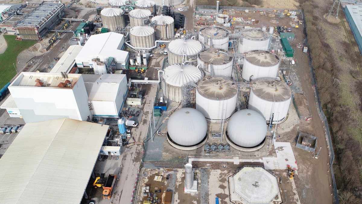
The first new biogas holder base and flare under construction – Courtesy of MMB
The key components of the STF refurbishment included:
- New liquid and cake sludge imports facility.
- Full M&E refurbishment of 4 (No.) digesters with the remaining two to be decommissioned.
- New digester sludge feed pumps, digester mixer pumps, heat exchangers and recirculation pumps.
- New biogas holders.
- New flare.
- New boiler.
- Integration of existing CHPs.
- New sludge dewatering centrifuges including polyelectrolyte and lime dosing.
- Ancillary HV supplies with improved ring main switching and control MCCs.
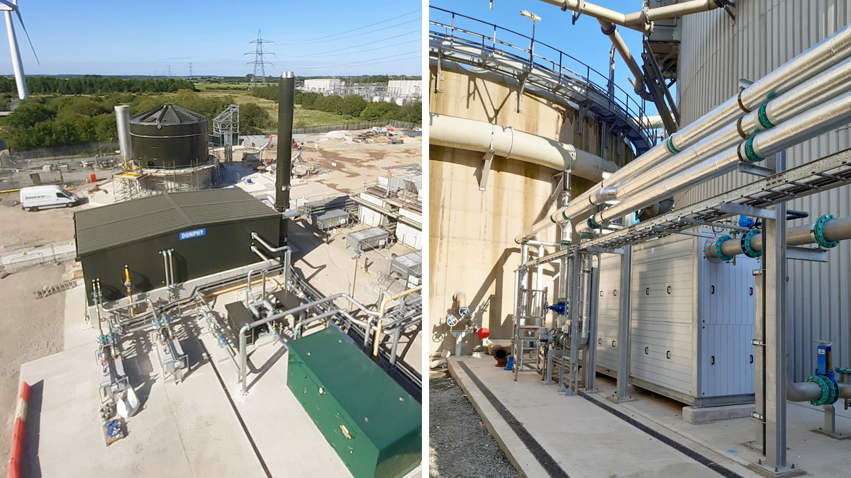
(left) New digester boiler house and liquid imports tank and (right) new digester heat exchanger and pipework – Courtesy of MMB
Hull WwTW: Inlet works & STF refurbishment supply chain – key participants
- Principal contractor: Mott MacDonald Bentley (MMB)
- Process designer: Mott MacDonald
- Piling: Keller Ltd
- FRC: Overhall Contractors Ltd
- Demolition: Ron Hull Demolition Ltd
- Shoring/temporary works: National Trench Safety UK
- Digester cleaning: GTS Nitrogen Services Ltd
- Ground stabilisation: DNS (Midlands) Ltd
- Precast concrete inlet structure: Shay Murtagh Precast
- Tank construction: Goodwin Tanks Ltd
- Mechanical installation: Alpha Plus Ltd
- LV: Circle Control & Design Systems
- HV: Freedom
- HV: Schneider Electric Ltd
- Boiler: Dunphy Combustion Ltd
- Cake imports: CTM Systems Ltd
- Centrifuges: Alfa Laval Ltd
- Feed pumps: EMS Industries Ltd
- Large scale blending (back mixing) PC pumps (Hull): SEEPEX UK Ltd
- Flare stack: Flare Products Ltd
- Gas boosters: Utile Engineering Co Ltd
- Gas holders and heat exchangers: Biogas Products
- Grit removal: Tuke & Bell Ltd
- Kiosks: NPS GRP Ltd
- Lime and ferric dosing: Ross-shire Engineering Ltd
- MCC panels: Technical Control Systems Ltd
- Metalwork: Galliford Try Fabrications
- Mixer pumps: Hidrostal Ltd
- Odour covers: Air-Water Treatments Ltd
- Odour control: Odour Services International Ltd
- Penstocks and stop logs: IQ Engineers Ltd
- Polymer dosing: Northern Pump Suppliers Ltd
- Screens: Fine, coarse and sludge: Huber Technology
- Skip compactors: Challenger Handling Ltd
- Sludge pumps: Xylem Water Solutions UK Ltd
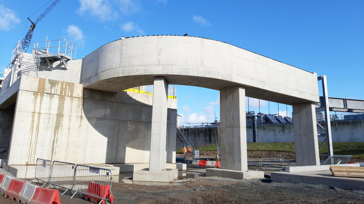
In situ reinforced concrete approach channel to the coarse screens – Courtesy of MMB
Scheme constraints
Ground conditions: Geotechnical investigations revealed the site is located on soft alluvial deposits located at an approximate depth of 3m. These deposits posed to be problematic for the design and build of the new structures due to predicted large settlements with the proposed loads. Suitable founding conditions was not present until depths of around 20m, with a band of sand around 15m depth initially giving misleading pile sets until driven through to the desired level. Extensive piling was carried out over both areas of construction on the site, with over 220 (No.) precast driven piles used over the inlet works alone.
During construction the same ground conditions were to prove problematic for construction cranes and piling rigs. Temporary works to improve the ground conditions would have required between 650mm and 800mm of topsoil removal and replacement with graded fill and MOT type 1 aggregates. The areas required would have resulted in large amounts of waste material and extended programme from stripping and replacement of the material, that an alternative was sought. Using PowerCem RoadCem, the construction team were able create a suitable temporary works surface, using the existing ground material, with the addition of RoadCem which bound between 350mm and 450mm of topsoil together to provide a surface which had a higher bearing capacity and was able to distribute plant loads over a wider area. This not only saved critical programme time, but also reduced the amount of waste material removed from site. With consideration of the finished surface levels, the same temporary works platform was also utilised in the final road levels and pile cap design and levels.
Pea season: There are a number of pea growing farms located in East Yorkshire, with a central processing factory located within the Hull catchment. During the annual peak harvesting time, the treatment works sees an increased solids throughput from the pea crop, which increases the required capacity of the sludge treatment facility and the consequent gas production. The works are designed to meet the additional demand of the pea season however the construction programme for the STF works had to be centred around this annual peak demand as some switch-over activities could not be carried out during peak season.
Environmental permit: At the end of 2018, after commencement of the upgrade works, new regulations were introduced for environmental permits and the Environment Agency’s Best Available Techniques (BAT) methodology needed to be adopted. This resulted in the requirement for additional contained spill areas and dual containment of sludges and centrate pipework, allowing for monitoring of any leakage.
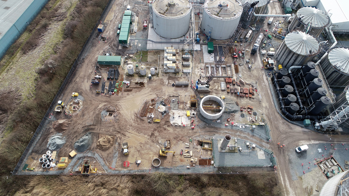
New sludge import facility under construction – Courtesy of MMB
Elevated inlet works
To eliminate the need for high level temporary works and speed construction, the decision was taken early on to incorporate the temporary works into the permanent works design. The raised inlet works was a combination of precast and in situ reinforced concrete elements. Prestressed bridge beams with an in situ topping were used to span between in situ support walls to create a level deck over 5m above ground level on which to construct the FFT channel walls. The FFT channel walls were in turn, a unique series of precast walls. Sockets were cast into the outer precast bridge beams to create virtually instant edge protection, allowing for safer working conditions whilst working at height to construct the channels, with shorter construction times. The bridge span lengths between the in situ walls were limited by the amount of pre-camber the beams had from pre-stressing the beams, as too much camber would result in excessive deflection under increasing loads, which could have potentially caused cracking of the precast FFT channel wall joints.
The three main construction elements of coarse screens, detritors and fine screens were connected with short lengths of in situ concrete channel walls to include expansion joints.
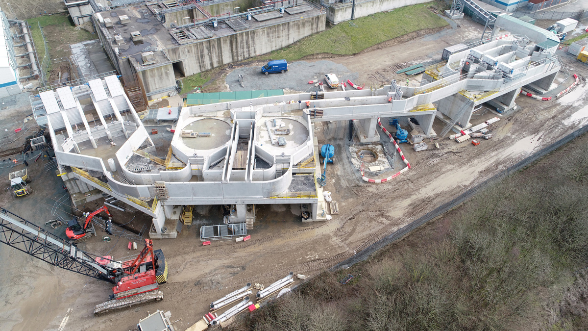
The new elevated inlet works, the majority of which is precast wall sections – Courtesy of MMB
Odour control covers
As part of the project, the inlet works was to be odour controlled to prevent release of untreated odours to the environment. Preliminary designs utilised a combination of glass reinforced plastic odour covers with metal decking walkways to areas where access and maintenance was required. However, using load bearing walk-on GRP covers the metalwork could be eliminated from over the channels with some isolated areas of cantilevered metalwork outside of the structure’s walls. This allowed for an increase in available working area as well as a more efficient design.
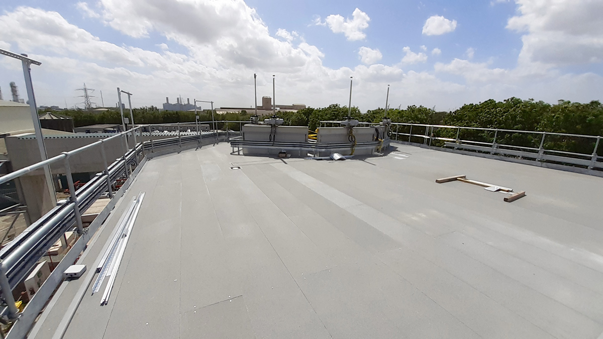
Walk-on GRP odour control covers from Air-Water Treatments Ltd over the new inlet works – Courtesy of MMB
Culvert crossing bridges
The scheme required a new access loop road to cross over the existing combined FFT and storm culvert which was not structurally suitable to carry vehicle loads. Due to the poor ground conditions the loads produced from the 6.8m spanning bridge would have resulted in settlement of approximately 100mm. The proximity of the existing 2m diameter final effluent outlet pipe limited the use of piling. Settlement calculations showed that if the loads could be transferred to a depth of 2m then the settlement was more reasonable and could be accommodated by allowing the bridges to settle before constructing the approach roads. Using foamed concrete which had a density of 900kg/m3 to a depth of 3m showed that the loads could be transferred to a lower level, whilst reducing surcharge pressures, without causing a load transfer onto the side of the culvert.
Drones
Throughout the project drones and laser scanning has been used to carry out surveys and capture aerial photography. During the first months of the project, in house drone pilots carried out unmanned flight surveys of most of the treatment works which allowed for the construction of a 3D Autodesk Revit models from the scans and provided additional confidence in the accuracy of the as constructed record information. Laser scanning of existing chambers allowed for measurements to be safely carried out without person access into confined spaces, which aided connection between the new FFT inlet works and the existing inlet works.
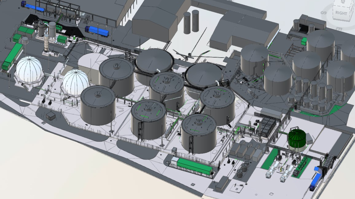
3D model of sludge treatment facility – Courtesy of MMB
BIM
Autodesk BIM360 with an Autodesk Revit based model was used as a lighthouse project within MMB, handling all graphical data. The 3D model was at the centre of the design, and with multiple subcontractors coordination was critical. Using Autodesk Revit, MMB were able to import separate 3D models into a master model, allowing for clashes to be found and models to be reviewed and accepted. BIM360 proved to be invaluable during the project with access easily available to required parties, and client reviews able to be carried out on the most up to date models. Access, lifting and maintenance studies and hazard and operability studies could be carried out virtually using the 3D models as a prompting aid to discuss proposed designs access, health and safety risks.
Scheme progress
Piling works began on the inlet works in June 2019 with the majority of the raised inlet works civils being completed before the end of the year. As of May 2020, much of the mechanical equipment has been installed, with the external works remaining and electrical fit-out being carried out by the middle of the 2020. The planned diversion to the new FFT inlet works is in September 2020.
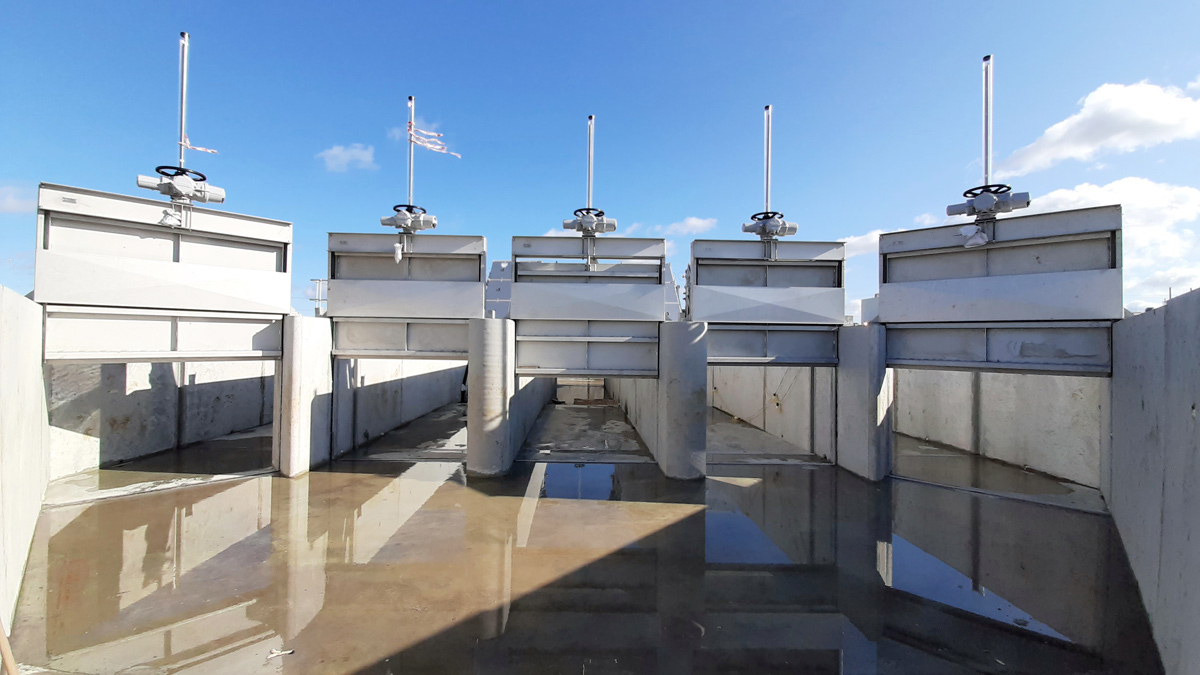
The new approach channel to the fine screens – Courtesy of MMB
Work began on the sludge treatment facility in late 2019 and is scheduled for completion in 2021. As of May 2020, the first phase of the digester refurbishment has been completed and two digesters are being brought into service prior to peak season 2020. The liquid and cake imports facilities are currently being installed and are due to be commissioned prior to the end of 2020.


