Lower Cleeve WwTW (2025)
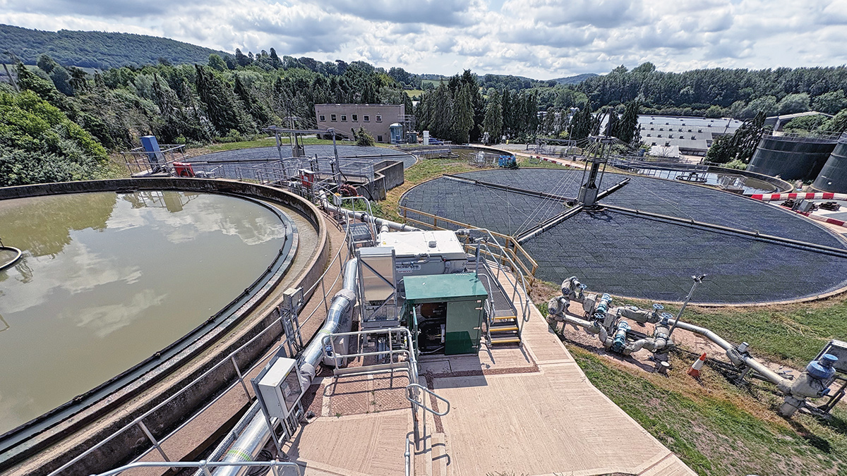
The new Salnes Filter and settlement tanks with Bio-Blok® 150 vertical flow media - Courtesy of MMB
Lower Cleeve Wastewater Treatment Works (WwTW) is situated in Ross-on-Wye, Herefordshire, serving the town and surrounding local villages. The works is subject to the requirements of the Environment Agency, WINEP U_IMP 5 (Flow to Treatment) and U_IMP 6 (Storm) driver with a deadline of 31 March 2025. Mott MacDonald Bentley was commissioned to carry out outline, detail design and build to implement the final solution to fulfil the regulatory drivers.
Existing works
The current treatment process comprised preliminary treatment where inlet escalator screens and detritors removed large debris and grit from sewage. Screened sewage flows are then dosed with chemical coagulant for phosphorus removal prior to primary settlement. Settled primary effluent is passed forward onto two stages of biological treatment followed by tertiary solids removal (TSR) plant for a final polish before being released into the River Wye.
Background
The objective of the U_IMP5 driver is to increase the existing permitted flows passed forward (FPF) to site to prevent the dry day operation of WwTW overflows. This is first identified by reviewing the ratio between full flow to treatment (FFT) to dry weather flow (DWF). Future FPF flows were investigated and modelled by Welsh Water’s Capital Delivery Alliance partner, ARUP. Their assessment reviewed growth projections and any implications to DWF and rate of maximum infiltration (IMAX).
The works receive intermittent flows from three pumping stations governed by their respective FPF permits. During inclement wet weather, this has resulted in the works being inundated with flows.
The existing primary settlement tank (PST) is hydraulically rated to treat up to 100 l/s but has, on occasions, received more flows than expected. Operator manual intervention has been required to over-pump excess flows into another asset to temporarily buffer flows. One solution was to build another identical radial PST, but land purchase was required, and the construction programme would not achieve the regulatory compliance date. An alternate solution was proposed using a Salsnes Filter from EPS Water, a mechanical belt filter with a small footprint that removed the requirement for land purchase.
Salsnes Filter
The Salsnes Filter was first developed in Norway, in 1991, to treat water in fish hatcheries using a rotating belt filter. To date, there has been hundreds of installations worldwide in municipal wastewater treatment plants, industrial applications such as tanneries, cruise ships, aquaculture, biofuel production, pulp and paper, and food and beverage. The Salsnes Filter is designed for solids separation, sludge thickening and dewatering in one compact unit.
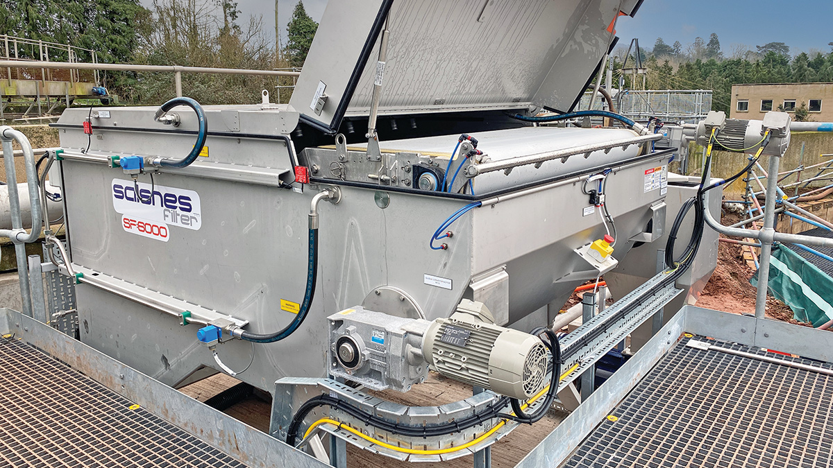
Salsnes Filter – Courtesy of MMB
The SF6000 filter unit was proposed to proportionally divert up to 50% of flows to support primary settlement during inclement weather.
Wastewater is fed into the unit and is distributed onto a filter mesh belt. The filter belt mesh is inclined and operates like a conveyor belt, effectively trapping larger suspended solids. Small particles will pass through the filter mesh and be discharged through the outlet for biological treatment.
As the belt rotates, the captured larger solids gradually compact under its own weight, leading to sludge to thicken. The thickened sludge is then dislodged from the top the belt with the sludge scraper, into to an auger, and deposited into a hopper. Sludge from the hopper is periodically pumped into an existing sludge holding tank, ready to be taken away for further treatment.
The Salsnes Filter is automated, minimising manual operator intervention while maintaining optimal performance. There are three wash cycles: high-pressure wash, lower-pressure wash, and scraper cleaning using potable water. Each wash cycle is adjustable based on time intervals or level. Periodically the filter is drained at the bottom to remove wash water and accumulated sediments and is discharged into existing site drainage.
Improving biological treatment
The existing cross-flow media was at the end of its design life, so MMB was tasked with replacing the existing media with Bio-Blok® 150 vertical flow media from Cougar Coatings Wastewater Division.
Each 25m diameter trickling filter was taken offline one at a time, with temporary treatment measures in place to maintain regulatory compliance. Existing filter media was removed within the week, paving way for the installation of new filter floor and Bio-Blok® media.
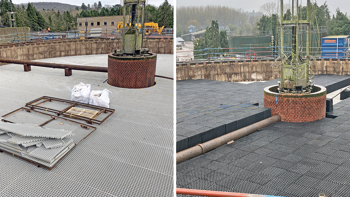
(left) Installation of new the filter floor and (right) Installation of new Bio-Blok® media – Courtesy of MMB
The primary function of the first-stage filter is for carbonaceous removal to reduce biological oxygen demand (BOD). The Bio-Blok® media has a distinct open mesh structure with helical net tubes, allowing more flows to be treated and providing a larger surface area for biofilm growth. This was demonstrated when the commissioning of the biofilter for BOD removal was completed earlier than the anticipated twelve-week filter seeding period, reducing temporary treatment requirements.
Lower Cleeve WwTW: Supply chain – key participants
- Principal designer & contractor: Mott Macdonald Bentley
- Network modelling: Arup
- Ground investigation: Dunelm Geotechnical & Environmental Ltd
- Electrical installation: Protocol Control Systems Ltd
- Systems integration: GPS Links
- Process solution – Salsnes unit: EPS Water
- Biological filter removal: Bagnall Construction Ltd
- Bio-Blok® biological filter media: BIO-BLOK an EXPO-NET brand
- Bio-Blok® installation: Cougar Coatings Wastewater Division
- Electrical survey & panels: GPS Group
- Temporary MBBR treatment plant: Siltbuster Group
- Mechanical pipework & fabrication: TEMA Engineering
- Submersible pumps: Xylem Water Solutions
- Potable booster pumps: Grundfos Pumps Ltd
- Valves: MJ Wilson Group Ltd
Minimising site disruption with DfMA solutions
Secondary treated effluent is pumped to a TSR plant for further treatment before being released from the outfall into the River Wye. The existing feed pumps were to be replaced to enhance efficiency and reliability.
The primary challenge was replacing the pumps without disruption to the operation of the TSR. Draining the pumping station wet well to replace the feed pumps would have necessitated complex over-pumping arrangement. Through consultation with the client stakeholders, site team and supply chain, a Design for Manufacture and Assembly (DfMA) solution was developed.
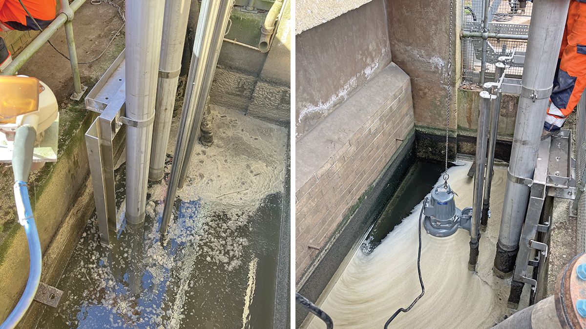
(left) DfMA TSR pump frame installation and (right) filter pump replacement – Courtesy of MMB
A stainless steel pump frame with associated pipework and a stainless steel gantry were manufactured off-site. The pump frame was lowered into the well and secured at the top, above the water level, eliminating the need for well drainage.
To ensure precise pump installation, the pump frame was engineered with integrated guide rails and lifting chains, allowing the pumps to be securely fastened to designated fixings. This controlled setup facilitated accurate placement, ensuring proper alignment and firm attachment to the frame, reducing the risk of misalignment or operational inefficiencies. Once in place, the pumps were prepared for electrical installation and connection to the permanent pipework.
During installation, temporary submersible pumps were deployed within the same PS well, positioned away from the permanent pumps and frame, ensuring continuous flow to the TSR and reducing compliance risks. This solution enabled off-site manufacturing and a drop-and-install system, effectively mitigating the risk of TSR feed disruptions and ensuring process compliance.
The same approach has been applied to meet the IMP_6 driver. The weir in the existing storm tank was increased to provide additional storage volume. The weir and scum board were fabricated off-site and installed during a dry day when the storm tank was empty.
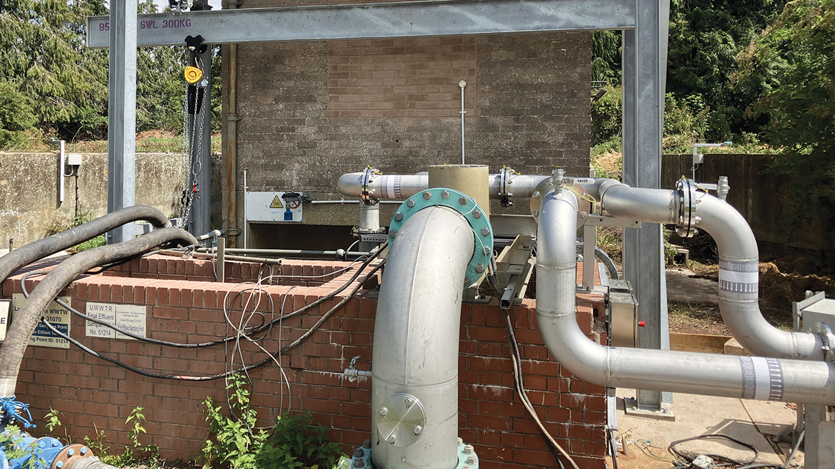
DfMA tertiary solids removal pumping station gantry – Courtesy of MMB
Conclusion
The upgrades at Lower Cleeve WwTW have increased treatment capacity. The introduction of the Salsnes Filter has provided a compact and automated solution at a fraction of a footprint of conventional PSTs and still achieve identical TSS removal rates.
The installation of Bio-Blok® media and TSR feed pumps were delivered with minimal process disruption. The DfMA weir plate solution has increased storm storage capacity on-site.
These collective improvements not only demonstrate that the regulatory requirements have been met but also establishes a robust framework for future operational resilience at Lower Cleeve WwTW.
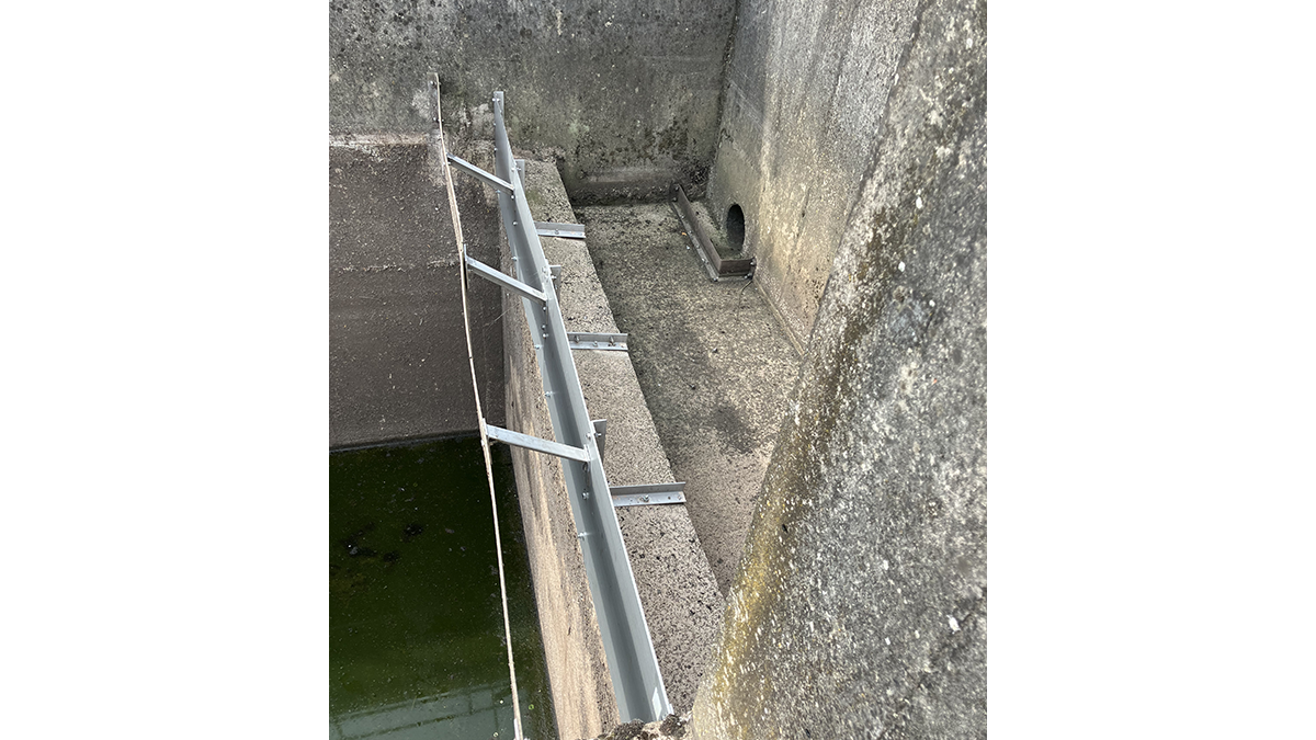
Side view of the DfMA storm weir modifications – Courtesy of MMB