Rotherwas WwTW (2024)
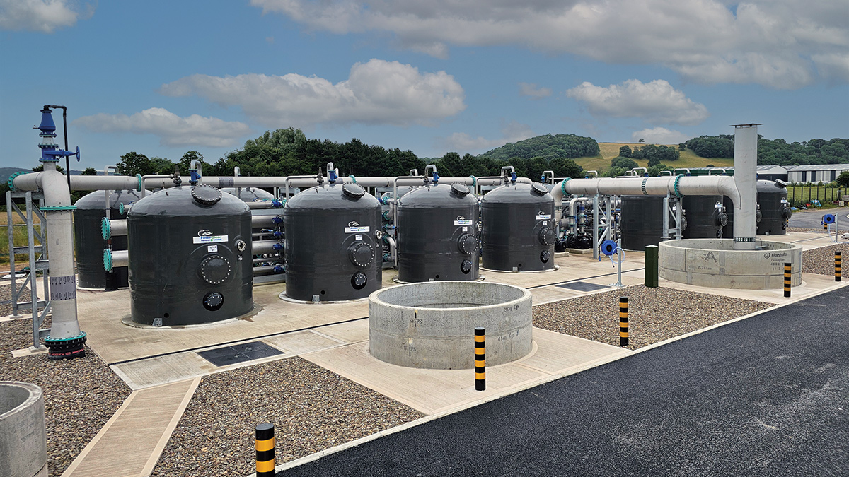
Rotherwas WwTW: Tertiary solids removal treatment from Bluewater Bio - Courtesy of Morgan Sindall
Sewage from Hereford and the immediate environs is treated by two wastewater treatment works: Eign WwTW and Rotherwas WwTW. The population served is 156,000 (2019), with a predicted population of 177,000 by 2040. Both sites are located in Hereford, England and fall under the responsibility of Welsh Water, with final effluent being discharged to the River Wye. All incoming flows are screened and de-gritted at Eign. Subsequently the flows are split at 60% to 40% ratio between Rotherwas and Eign, respectively, to undergo further treatment. This case study is focused on the modification works undertaken at Rotherwas. It should be noted that the chemical dosing plants at Eign have also been refurbished/upgraded to optimise phosphorus removal performance on that site.
Existing works & project need
Flows received at Rotherwas are split between four primary settlement tanks (PSTs). A portion of the effluent from the PSTs is pretreated by a high-rate filter (HRF) to lower biological load and then mixed with the rest of settled flow before passing to 18 biological filter beds. The effluent from the biological filters is dosed with poly aluminium chloride and flows into four humus tanks. Effluent from the humus tanks flows to the works outfall for discharge into the River Wye.
Due to the requirement for a new tighter discharge limit for phosphorus, reducing the total standard from 1 mg/l to 0.4 mg/l, Welsh Water was required to undertake modifications to both sites.
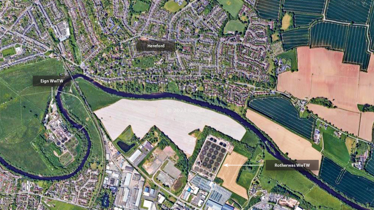
Google Maps image showing the site locations
Overview of works undertaken
To meet the new consents the following works were required:
- A new tertiary solids removal (TSR) plant along with new P removal chemical dosing systems.
- Full replacement of the P removal primary dosing system (PACL dose) due to the age of the asset.
- A tertiary dosing system (ferric sulphate dose) on the feed to the new TSR plant.
- An upgrade of the power supply at Rotherwas WwTW and the installation of a new HV substation.
The proposal also required an interception chamber located on the existing final effluent pipework, downstream of the humus settlement tanks, to divert flows to the new lift pumping station and further pass them onto the new TSR plant, incorporating 16 vertical (2.8m diameter) pressure filters.
The pumped feed to the new TSR will be dosed with ferric sulphate. Treated flows from the TSR will then gravitate via a drop chamber to the existing final effluent sample chamber and outfall to the river. The TSR plant will also incorporate a dirty backwash tank and pump return system, that will pass filter backwash returns to the works reception chamber.
Interception chamber, sample chamber and outfall
A new outfall interception chamber was installed on the existing live final effluent pipework (1m diameter and approximately 4m deep), between the existing humus tanks and sample chamber.
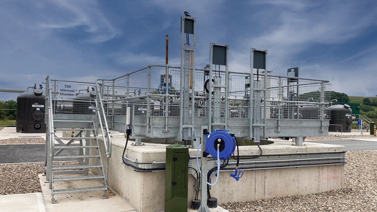
Interception chamber – Courtesy of Morgan Sindall Infrastructure
The interception chamber facilitates diversion of humus tank effluent to the new lift PS, which feeds the new TSR plant; it also provides an emergency overflow to bypass the lift pumping station. The emergency overflow incorporates an actuated overflow weir which operates automatically to prevent back flooding of the existing humus settlement tanks under certain high river level conditions. The chamber is a 4m diameter structure, 4m deep.
Due to the chamber being built over the live pipework, a Business Continuity Plan had to be in force during construction. This meant that 24/7 over-pumping was in place to pump the pass forward flow of 574 l/s, as required. Construction of the chamber required a cofferdam, which was sunk using a Movax (vibrating hammer attached to 32T machine). The final effluent pipe was carefully exposed, then cut using wire rope.
New sample chamber level instruments and duty/standby progressive cavity sample pumps complete with necessary pipework and pressure instruments were installed by the existing sample chamber. The pumps provide a continuous flow for the new final effluent sample instruments installed within the existing sample kiosk: pH, total suspended solids, ortho-phosphate, soluble iron and soluble aluminium.
Rotherwas WwTW: Supply chain – key participants
- Designer: Arup
- Main contractor: Morgan Sindall Infrastructure
- Shaft supplier/designer: B&W Tunnelling Ltd
- Structural slabs: Adfil
- Tertiary solids removal plant: Bluewater Bio Ltd
- Mechanical design/installation & steelwork: Industrial Pipework Services (IPS) Ltd
- TSR lift pumps: Xylem Water Solutions
- Dirty backwash return pumps: Mono Pumps
- Dirty backwash water tank: Goodwin Tanks Ltd
- Chemical dosing plant: Colloide
- LV installation: Protocol Control Systems (PCS) Ltd
- MCC supply/installation: General Panel Systems (GPS)
- 11kV supply/installation (including switchgear & transformers): Hornbill Engineering Ltd
- Pumping specialist: Hydrainer Pumps
- Flow controls: AFFCO Flow Control (UK) Ltd
- Valves: AVK UK Ltd
- Static mixer: Statiflo Ltd
- FE analysers: Partech Instruments
- Safety showers: Hughes Safety Showers
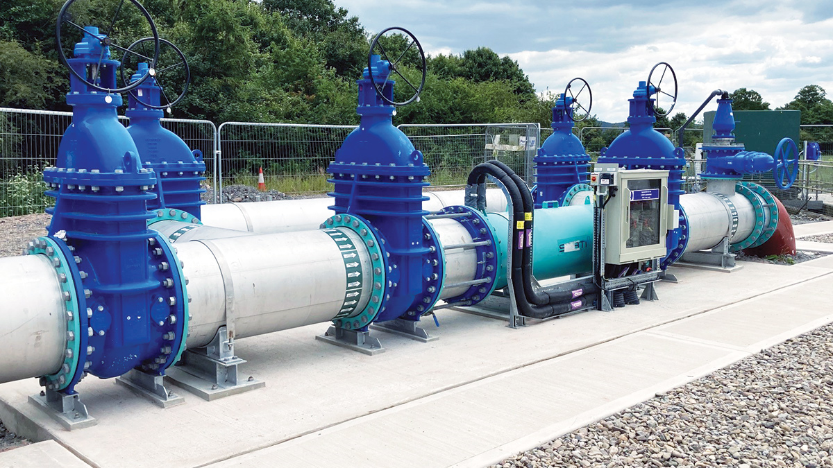
Tertiary dosing POA and bypass – Courtesy of Morgan Sindall Infrastructure
Lift pumping station
A tertiary solids removal lift pumping station was required to provide the motive pressure and flow for the TSR filtration process. The selected TSR technology consists of multi-media pressure filters in above-ground vessels. The pumping station consists of a wet well with three variable speed submersible pumps (duty/assist/standby) to provide the maximum flow rate (574 l/s) required for the new TSR plant. The pumps are controlled by variable speed drives to cater for the fouling of the multimedia pressure filters during operation.
Level instrumentation for controlling the lift pumps was submerged pressure transducers, as the works suffer from severe foaming during certain periods, and this allows for continued effective control as the ultrasonic signals would be lost during these events.
A 1.5m deep by 1.2m wide collar was constructed to enable the installation of the 8.2m diameter wet well, which was constructed with precast concrete segments. The shaft segments were sunk approximately 8m below ground level and a 1.7m deep concrete plug was cast at the base of the shaft. During shaft construction, local ground dewatering was installed within the shaft. Groundwater was pumped into settlement tanks and then into recharging wells approximately 70m away.
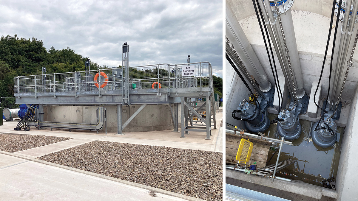
External lift pumping station – Courtesy of Morgan Sindall Infrastructure and (right) Lift pumping station: Installed pumps during construction phase – Courtesy of Arup
Tertiary Solids Removal (TSR)
Several options were considered for the tertiary treatment stage; all of which achieved the necessary solids removal and P performance.
They were assessed against a number of criteria and the FilterClear process from Bluewater Bio Ltd was selected. It should be noted that a major constraint was space on site, and the Bluewater Bio plant’s low footprint meant that it could be located within the existing site boundary, avoiding use of the neighbouring field which is prone to flooding.
There were two options for the Bluewater Bio Ltd package:
- First option: 4 (No.) 3.7m diameter, 8m long horizontal filters.
- Second option: 16 (No.) 2.8m diameter vertical filters.
The vertical filters option was selected due to the following:
- This option could fit within the existing site boundary.
- Smaller backwash pumps were required.
- Smaller blowers were required.
- A reduced capacity dirty backwash tank was needed.
- A TSR treated clean water tank for backwash water was not required.
- There was reduced hydraulic impact on the works’ inlet receiving chamber (which was already hydraulically challenged).
- There was greater system redundancy to support operation and maintenance activities.
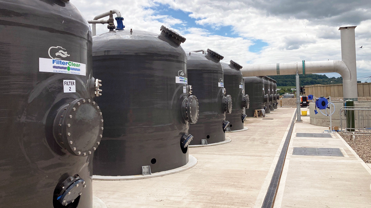
Bluewater Bio Ltd’s tertiary filters – Courtesy of Morgan Sindall Infrastructure
The filters were specified to achieve the following process performance at the 95-percentile limit:
- Total suspended solids: 10 mg/l.
- BOD: 28 mg/l.
- Ammonia: 10.3 mg/l.
- Phosphorus: 0.32 mg/l.
The treated effluent from the TSR plant will pass by gravity directly to the existing sample chamber and outfall. An energy dissipation drop chamber was also installed to receive the treated effluent from the TSR; this aided the hydraulics and allowed a controlled flow to the downstream existing sample chamber.
Dirty backwash & wastewater management
Bluewater Bio Ltd confirmed that there was no need for a clean water storage tank for backwash purposes as there was sufficient water volumes within the TSR filter system. Therefore, backwash water is taken directly off the filter outlet manifold and pumped through the filters via backwash pumps. Air scouring is also carried out as part of the backwash process. Filters are called to wash on pressure differentials across the filter bed and/or timed intervals.
The dirty backwash waters from the filters are conveyed to the dirty backwash water storage tank. This storage tank is 7.7m internal diameter by 9.9m high and has a suitable operating volume of 412m3.
This volume allows for effective metering/smooth delivery of the dirty washwater back to the head of the works at the inlet receiving chamber. This is important as the instantaneous backwash pump flow rate is too high to be accepted by the works.
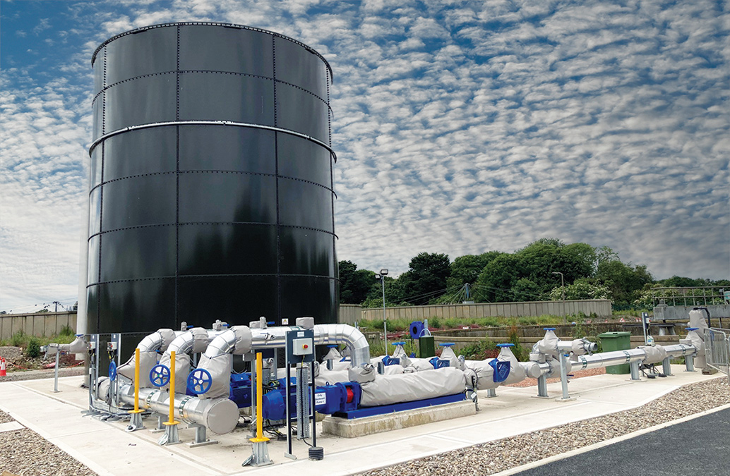
Dirty backwash tank and returns pumping station – Courtesy of Morgan Sindall Infrastructure
The captured dirty backwash water in the storage tank is returned via three variable speed progressive cavity pumps operating in a duty/assist/standby mode. The need for progressive cavity type pumps was driven by the required operating envelope for effective flow rate returns. The flow and volume of the backwash water return is monitored and recorded via an electromagnetic flow meter which will be used as part of the M-Certed site flow monitoring.
The backwash return flow rate range is 30 l/s to 89 l/s depending on levels within the storage tank.
A gravity return feature has also been installed as a bypass around the backwash return pumps, which can be used as an alternative when operating conditions allow.
Chemical dosing
To ensure the effective removal of phosphorus in the treatment process, two new chemical dosing systems were installed. The first provides primary dosing (PACL dose) upstream of the PSTs and includes a single storage tank of 62m3 and a dosing kiosk housing duty/standby pumps.
The second chemical plant provides tertiary dosing (ferric sulphate dose) directly into a static mixer on the TSR rising main, which feeds the TSR filters; it also includes a single storage tank of 57m3 and a dosing kiosk housing duty/standby pumps.
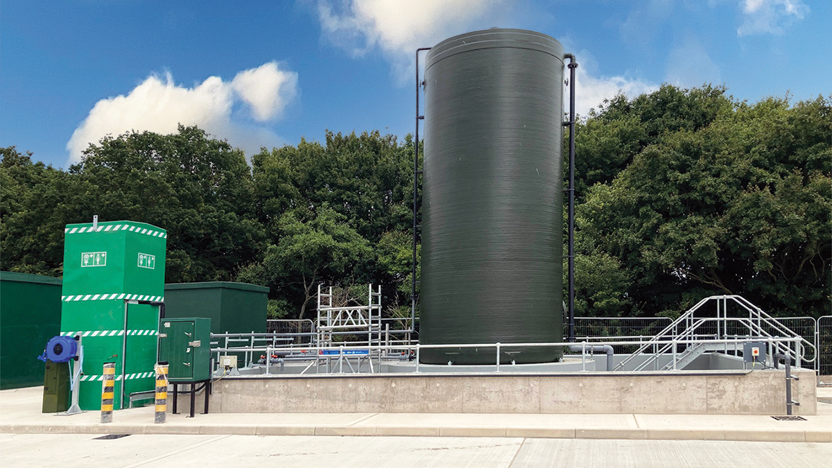
Tertiary dosing plant – Courtesy of Morgan Sindall Infrastructure
Construction & programme
There were several significant construction challenges experienced on site. The major one was the limited space available within the construction area. This led to a potential congested working area with up to 50 personnel on site at the same time, working in close proximity to one another. This required the construction programme to be carefully planned and coordinated to ensure that the works were constructed safely, with relevant segregation, and to ensure the protection of the work force at all times.
Another challenge was ensuring the treatment works were running effectively at all times and maintaining compliance as to no cause detriment to the existing process. To enable the treatment works to remain operational during the construction of the new assets especially the interception chamber, which was constructed over the existing live final effluent pipe, several Business Continuity Plans (BCPs) were compiled and agreed with the client and operations collaboratively.
Significant over-pumping (up to 600 l/s) needed to be in place for approximately 10 weeks, requiring 24/7 operation with duty and standby pumps, pump-men attendance, and on call to ensure that there was no risk of breaching the EA discharge permit.
Several major BCPs were required for the following works:
- Running newly constructed part of site from 800kVA generators, to commission the new plant before it was transferred onto mains power.
- Replacement of existing 500kVA transformer with the whole site running on temporary power generation.
- Site investigation works for the existing rising main crossing which required over-pumping for the de-sludge pumping station.
A number of smaller BCPs were also in place for the EICA works, including power and signal cable installation.
The planning of the construction works was crucial, as the 18-month programme was extremely tight. This meant that there was little float during the construction period.
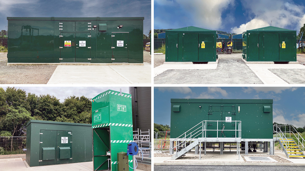
(top left) HV switchgear kiosk, (top right) RMU kiosks, TSR secondary dosing kiosk & safety shower, and (bottom right) MCC kiosk – Courtesy of Morgan Sindall Infrastructure
Innovations
There were several innovations on this project covering different aspects including operation, Health & Safety/CDM, environmental and TOTEX savings. Two of these innovations are outlined below.
Lift pumping station baffle wall: The design called for the 2.5m high and 5.6m wide baffle within the 8m deep 8.2m diameter wet well; the baffle invert had to be installed 1m above finished floor level, supported off the side benching. The original design intent was for the baffle to be a stainless steel plate; however, this became cost prohibitive, resulting in a change to a concrete structure, which would be cast in situ.
However, to maximise best Health & Safety practices, it was proposed to construct the baffle wall as a precast element on site, at ground level. The precast wall weighed approximately 11 tonnes and was installed within the pumping station using a 200T crane. This greatly reduced the Health & Safety risks (limiting confined space working) and allowed for better quality control of the shuttering frame. Off-line construction also offered a safe working area for the shuttering team, steelwork fixers and better access for the concrete pour. There was a remaining risk associated with lifting a large element into position within the wet well.
To overcome this, an enhanced lifting arrangement was developed which involved the local reinforcement of the baffle alongside special fixings (lifting eyes) which could be removed upon completion. The benching concrete also had to be evenly poured around the wall to ensure its stability in the temporary case.
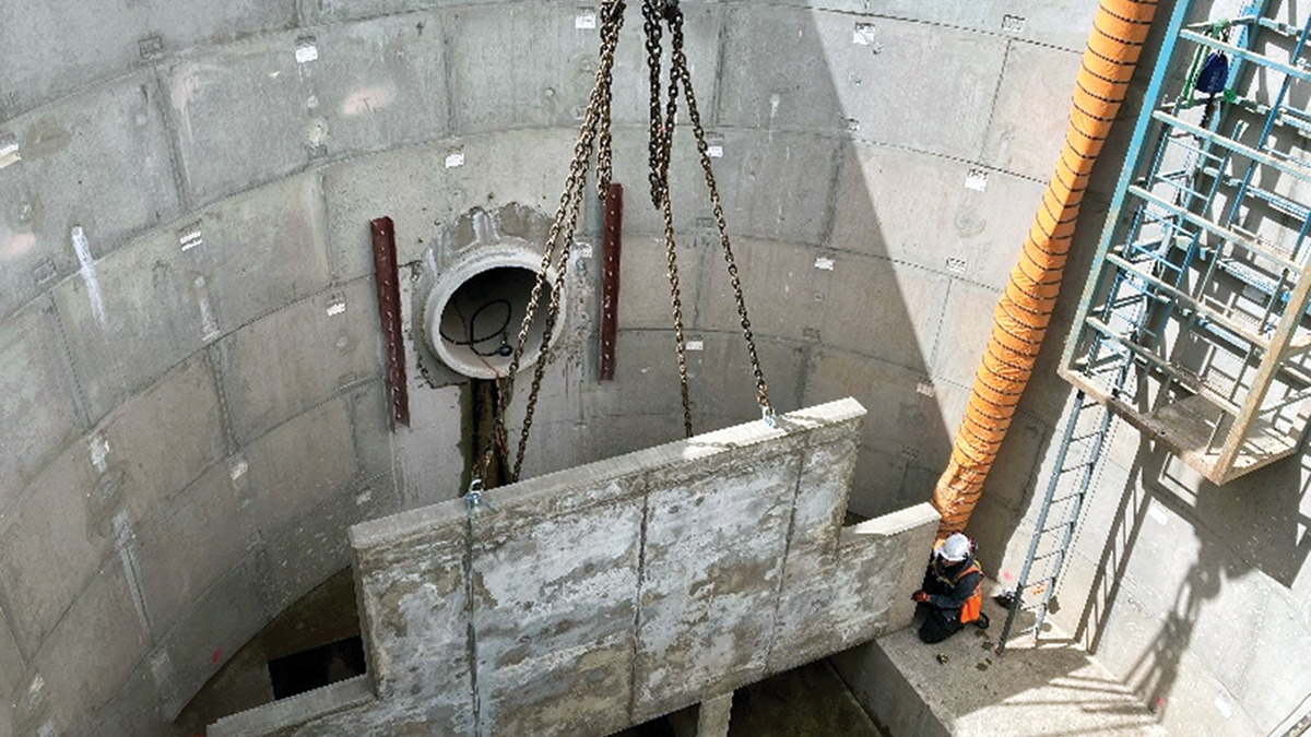
Rotherwas internal lift PS craning in of the baffle wall – Courtesy of Morgan Sindall Infrastructure
Clean water tank for TSR backwash process: The initial proposal was to construct a 226m3 clean water storage tank for the backwash process. However, this was associated with significant cost and there was insufficient space on the site for this to be located. The team challenged the requirement for this tank and, with the support of Bluewater Bio Ltd and Welsh Water’s Operations team, a risk-based analysis was carried out which concluded that the tank was not required. This was due to the sufficient storage in the filter system, ensuring effective backwash under all operating conditions.
Project completion
Welsh Water have invested £30m at Eign and Rotherwas WwTWs. These phosphorous removal schemes are part of a programme of upgrades to existing wastewater treatment works that will improve water quality in the rivers. Lessons learnt from these schemes have been used by Arup and Morgan Sindall and shared with the Welsh Water Capital Delivery Alliance partners to improve scheme delivery of other rural wastewater treatment works.
Early contractor engagement with mechanical subcontractors, chemical dosing suppliers, and DfMA MCC suppliers, helped achieve significant design and construction efficiencies.
Eign and Rotherwas WwTWs were completed in line with achieving the new tighter P permit by the end of March 2024.


