Queensferry WwTW (2024)
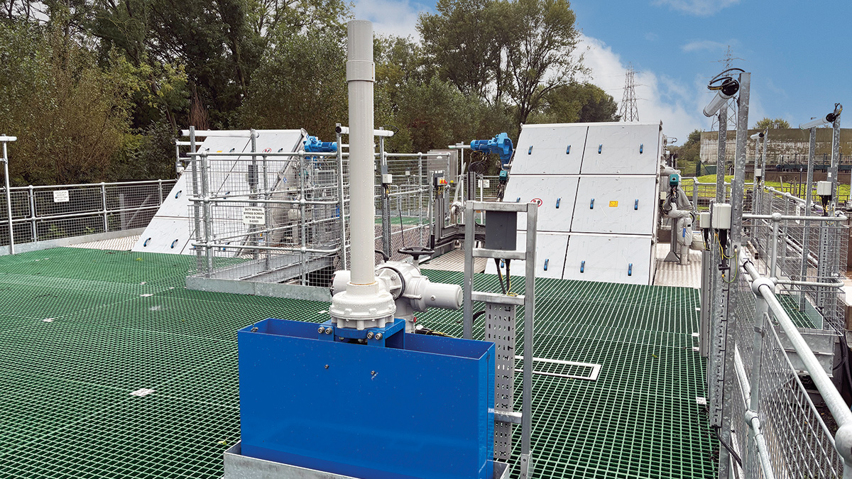
New Huber Technology escalator inlet screens - Courtesy of Morgan Sindall Infrastructure
Queensferry Wastewater Treatment Works (WwTW) is situated on the banks of the River Dee in North Wales serving a population equivalent (PE) of 55,100 (split 60% domestic/40% trade), with catchment growth expected to increase to 62,830 PE by 2040. Currently, all flows arriving at the works discharge through a series of bellmouths into a single covered reception chamber. There are 12 bellmouths discharging a mixture of gravity and pumped rising main sewage. In addition to domestic sewage, the works received high trade concentration and tanker imports. The combination of gravity and pumped flow has been detrimental to the inlet works structure and plant including; 6mm escalator screens, macerator, grit traps and associated grit classifiers with corrosion present from hydrogen sulphide (H2S) attack. The harsh environment, along with the projected growth has led to the inlet works being identified as at end of its working life.
Background
The reinforced concrete reception tank and inlet channels were constructed in the late 1970s and were originally covered with open mesh galvanised steel flooring. To resolve odour concerns, the covers were replaced with solid covers in the late 1990s, in addition to the installation of odour extraction equipment and a ferric chemical dosing system.
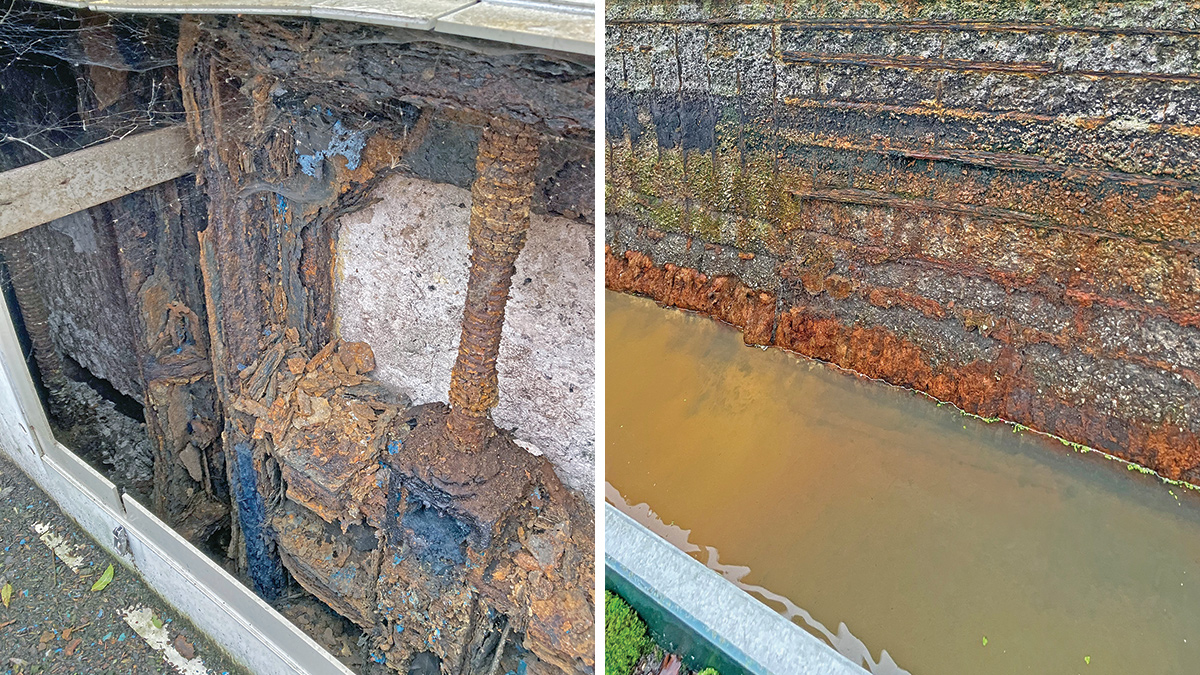
Hydrogen sulphide attacks: (left) to the existing isolation penstocks, and (right) to the existing inlet channel walls – Courtesy of Morgan Sindall Infrastructure
The covering of the inlet channels, together with poor odour control arrangements, sped up the chemical corrosion to the internal surfaces of the channel caused by hydrogen sulphide (H2S), with particular effect on the concrete wall surfaces located above the water level. H2S has also corroded the plant and equipment located below the covers. To summarise:
- The internal walls of the channel showed signs of degradation and loss of aggregate materials allowing exposure of the original reinforcement steel mesh and beyond in a number of places.
- Channel covers, particularly their supporting frame fixings into the concrete channel have become loose – the worst affected located nearest the inlet rising main bellmouths.
- Corrosion of all channel isolation penstocks making them inoperable.
- Surface corrosion of the original handrailing system which surrounds the edges of the inlet channel.
- All associated grit trap plant and equipment are disused.
Solution
The project has been released by Welsh Water to Morgan Sindall to provide a resilient and safe inlet works able to treat both gravity and pumped flows from the existing incoming pipelines as well as making provision for three additional incoming rising mains from known future developments.
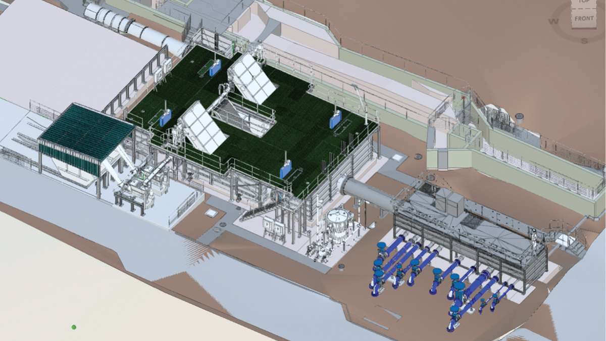
3D model of the existing and new structures – Courtesy of Arcadis
The scope of the project is to provide a new inlet works comprising:
- Diversion of the 12 incoming pipelines to connect into a new reception chamber.
- Provide a replacement inlet reception tank with associated odour control unit and tanker import connection.
- Provide duty/standby 6mm – 2D screening arrangement complete with duty/standby screen handling units suitable for both current and predicted incoming flows to 2040 growth.
- Refurbishment of the original grit settlement traps and associated grit removal plant and equipment.
- New MCC and kiosk to service the new inlet works plant and equipment.
- Decommissioning of the existing inlet plant.
Solution overview
The system was required to be safe, energy efficient, and conform to legislative requirements, Welsh Water internal specifications, and current best practice.
Due to the condition of the existing reinforced concrete reception tank and inlet screen channels, the Arcadis design team identified the need to build the new reception tank of a resilient material. Stainless steel was selected as a proven, resilient material to deal with H2S attack.
Queensferry Inlet Works: Supply chain – key participants
- Principal designer & contractor: Morgan Sindall Infrastructure
- Designer: Arcadis
- Civil groundworks: William Hughes Civil Engineering Ltd
- Piling: Universal Piling
- Grit trap & channel de-silting/cleaning: Celvac Ltd
- Overpumping: Pump Supplies Ltd
- Overpumping: Selwood
- Mechanical installation: Whitland Engineering Ltd
- MCC, ICA controls & electrical installation: Lloyd Morris Electrical Ltd
- Systems integration: Merlin Systems Ltd
- Inlet screening: Huber Technology
- Odour control: Air-Water Treatments Ltd
- Grit plant: Tuke & Bell
- Pumps: Xylem Water Solutions
- Flow controls: AFFCO Flow Control (UK) Ltd
- Drawpit manufacturer: Cubis Systems
- Combined booster set kiosk & tank: Dutypoint Ltd
- Bollfilter manufacturer: Bollfilter UK Ltd
- Pipework manufacturer: Wavin Osma
- Drainage solution: ACO Water Management
- GGBS (admixture) supplier: Civil & Marine Ltd
- Cement supplier: Castle Cement Ltd
- Concrete supplier: Hanson UK
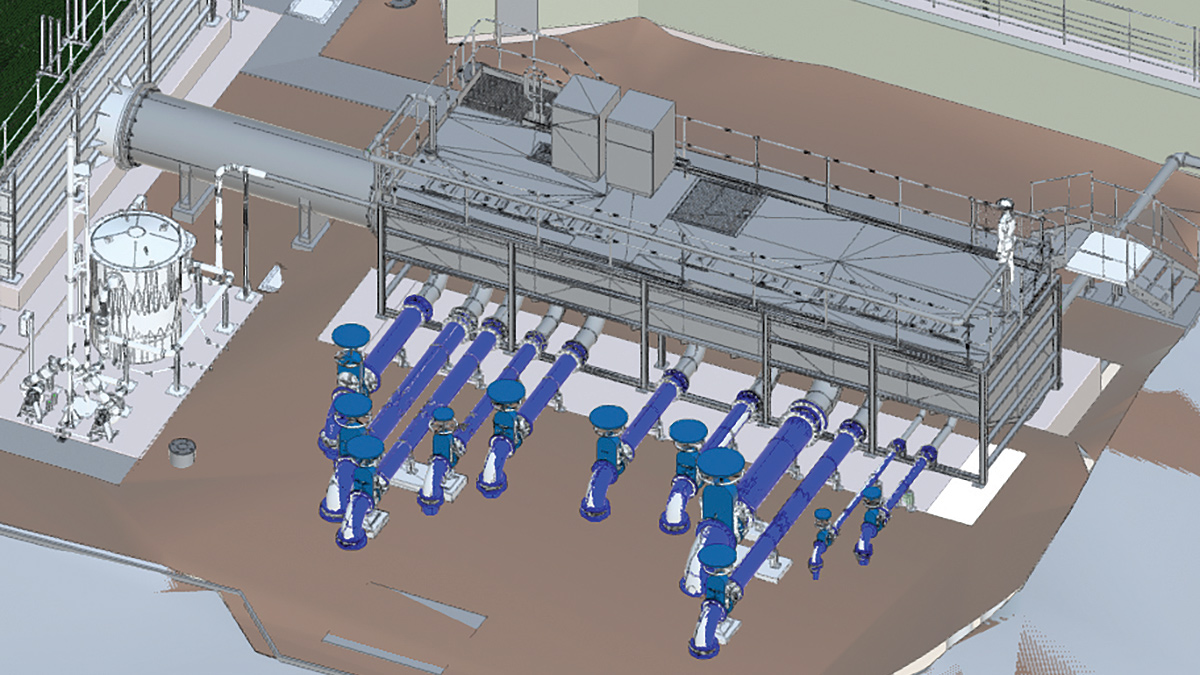
3-D model showing all pipelines rising from ground and entering reception tank – Courtesy of Arcadis
Hydraulic & connectivity assessment
An initial hydraulic assessment was carried out to determine the impact of the top water level (TWL) for the proposed inlet arrangement over the existing inlet bellmouths for the future maximum design flow. It was found that under normal operation, the TWL in the new reception chamber would be approximately 500mm above the existing bellmouth levels, leading to reverse flow and hydraulic restrictions.
With the increase in levels, a connectivity study was undertaken to determine impact on the incoming gravity and pumped inflows. This highlighted a number of connections to be higher risk with the works being undertaken, in particular the site returns and gravity/siphon sewer from the adjacent catchment. Investigation was undertaken to determine the impact of high level of water in the reception tank on the incoming gravity/siphon sewer.
The modelling results indicated that the last-in-line catchment CSO consents were still met.
Replacement of reception chamber
The placement of the replacement reception tank proved challenging. Two options were considered, both of which came with their different hazards and risks.
- Take the existing chamber offline and replace in situ: This would require the diversion of all the incoming below-ground incoming mains and sewers into a temporary reception tank, through temporary screens before connecting back into the inlet channel.
- Construct a new tank offline, adjacent the existing structure (to the left, or right): This option would require either extending the incoming pipelines through the existing reception channel, or building over the existing incoming pipelines, dependent on which side of the existing reception tank the new structure was constructed.
Early in the design stage it was decided that rather than constructing a temporary reception tank, making the tank permanent would provide longevity and reduce whole life cost. The tank was to be located on the side where the existing sewers and rising mains enter the treatment works. This allowed the new screens to be constructed off-line and then connect back into the existing inlet channel upstream of the grit trap.
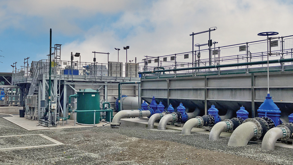
Installed reception chamber and rising mains – Courtesy of Morgan Sindall Infrastructure
Incoming pipeline constraints
The reception tank was to be located over the existing incoming rising mains and gravity sewer siphons. These pipelines have been in the ground since the construction of the existing reception chamber construction and the conditions were unknown. To minimise additional stress whilst the tank was being constructed, Arcadis designed a bridging slab to span across the pipelines.
Morgan Sindall undertook numerous surveys – initially ground penetrating radar (GPR) – before carrying out a vacuum excavation (VacEx) to accurately pinpoint the location of each pipeline.
Once each pipeline was located, its exact location was mapped, to allow a 3D model to be generated detailing the connections of each pipeline into the pre-fabricated steel reception tank.
Reception tank & screen channels
The surveys and 3D model allowed the mechanical installation contractor, Whitland Engineering Ltd, to design and construct a DfMA reception tank (11m long x 3m wide and 2.5m high), which incorporated all of the incoming pipelines, including internal rising bellmouths and three blanked-off connections for future use as part of the River Dee rising main diversion scheme being undertaken by Welsh Water.
Stainless steel was selected to provide additional resistance to H2S and increase longevity. This material also reduced the additional overburden the existing rising mains would be subjected to during construction.
Due to existing ground conditions, it was confirmed that to minimise further the additional burden on the existing rising mains, the bridging slab required to be piled. A 15m long bridging slab was then constructed in situ to span the existing incoming pipelines.
The DfMA continued with the off-line installation of the new inlet screens and screen chamber. The reception tank and inlet screen chamber (10m long x 2m wide x 2.5m high) were linked by a 1,200mm stainless steel pipe. Two 6mm-2D escalator screens from Huber Technologies were installed within the new tanks. The screens will operate duty/standby, sized for the future maximum flow of 784 l/s. Screenings drop into a common launder trough before discharging into two duty/standby screening handling units.
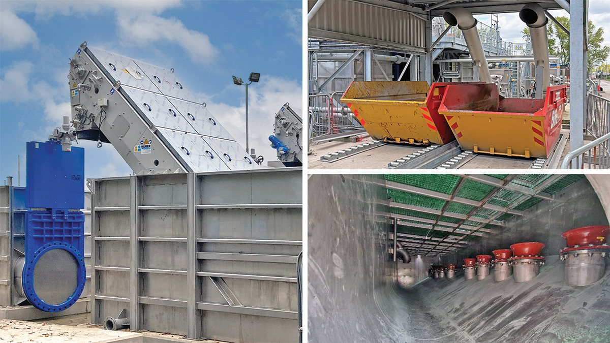
(left) DfMA installation of new inlet screens and chambers, (top right) the screenings skip canopy, and, (bottom right) internal photograph of bellmouth discharge points in reception tank – Courtesy of Morgan Sindall Infrastructure
MCC
The Morgan Sindall/Arcadis team which delivered the Leominster WwTW phosphorus removal scheme was instrumental in working with Welsh Water to create a standard product in the form of a new low voltage distribution board kiosk and a new tertiary filter MCC kiosk.
The DfMA GRP kiosks are mounted on a raised steel frame floor to support the MCC and the access covers while giving ample space beneath the structure for cable connections and testing.
This kiosk design reduced H&S risks associated with installation and commissioning and led to considerable reduction in installation time on site, as the kiosks were delivered to site, off loaded, and fixed down, all within a few hours. The standard product was utilised for the Queensferry project, with a 7.5m long x 3m wide x 3m high installation adjacent the new inlet works.
Odour control unit
Due to the high level of hydrogen sulphide arriving at the reception tank and the risk of aerosols from the bellmouth discharge, the reception tank and screenings chamber have been designed to be covered.
To mitigate odorous gas build-up, a new odour control unit has been installed replacing the end-of-life existing unit. An Air-Water Treatments Ltd Peacemaker™ P2000 duty/standby unit has was selected.
Grit detritors
The final scope element for the project is the refurbishment of the existing two grit detritors, grit rakes and organic return pumps. To allow the grit detritors to be taken off-line, the new reception tank and inlet screens required to be operating in full and bypassing the grit trap (see commissioning sequencing below).
To enable this to happen, an additional chamber was constructed downstream of the inlet screens, which allowed all flows to run through a number of temporary above ground pipes, before discharging into the existing continuation channel downstream of the grit trap.
Once isolated, the inlet channel and grit detritors were cleaned out. Approximately 53,300kg of grit was removed. The existing grit plant; detritors, grit rakes, organic return pumps and inlet baffles were removed, as well as the existing GRP covers, which provided odour suppression. Tuke & Bell then installed replacement grit detritors, rakes, pumps and inlet baffles.
To allow future isolation for maintenance, four new isolation penstocks were installed at the inlet and outlet of each detritor.
The permanent connection from the new inlet screens into the existing inlet channel was carried out through hydro-demolition of the existing wall at the same time as the works to the grit trap.
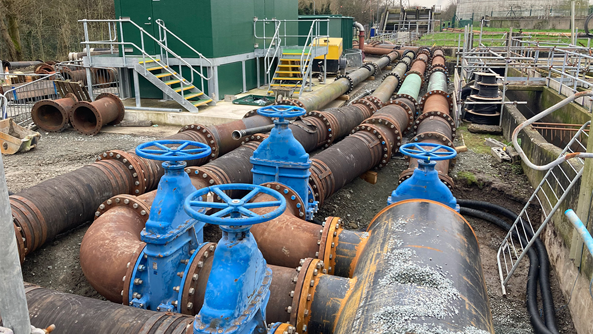
Overpumping manifold to isolate existing inlet works and grit plant – Courtesy of Morgan Sindall Infrastructure
Commissioning sequencing
Once dry commissioning was complete, the inlet screens required flow to carry out wet commissioning. To minimise the impact of untoward/non-operational screening, the flows from each main were switched sequentially with support from Welsh Water Operations controlling the flows from the network pump stations.
This allowed partial flow from the old reception chamber to the new to prove the operation of the new screens before all the rising mains were transferred.
Once the screens were proven operational, the remaining rising mains and gravity siphons were switched between the old and new reception tanks, allowing the grit trap to be isolated.
Conclusion/summary
Works began on site on 22 September 2022, with the major civils components completed in September 2023 and the M&E completion of the inlet works at the end of March 2024. All incoming flows were fully transferred from the old reception tank to the new reception tank by the end of May 2024, allowing the grit chamber to be isolated.
At the time of writing (July 2024) activities on site include the installation of the grit/silt washpactor and skip canopy. The project is forecast to be completed on site by the end of August 2024, with handover to Welsh Water by October 2024.


