Ammanford Flood Risk Management (202...
The town of Ammanford, Carmarthenshire has a history of flooding. Several significant flood events have been recorded since 1979 and most recently in 2009, with homes, businesses, roads, the Heart of Wales railway line and a local college inundated. Natural Resources Wales (NRW) commissioned Arup and Walters to design and construct a solution to reduce the community’s flood risk and improve fish passage. This project innovatively aligns solutions to reduce risk to the community from flooding with two other previously separate schemes; safeguarding a critical sewer crossing found to be in poor condition and addressing a significant barrier to migratory fish.
Project scope
With limited public funding and the increasing need for multifunctional infrastructure enhancements, the scheme offers lessons in the delivery of multiple benefits. The scheme comprises:
Seven concrete flood walls.
Two earth flood bunds.
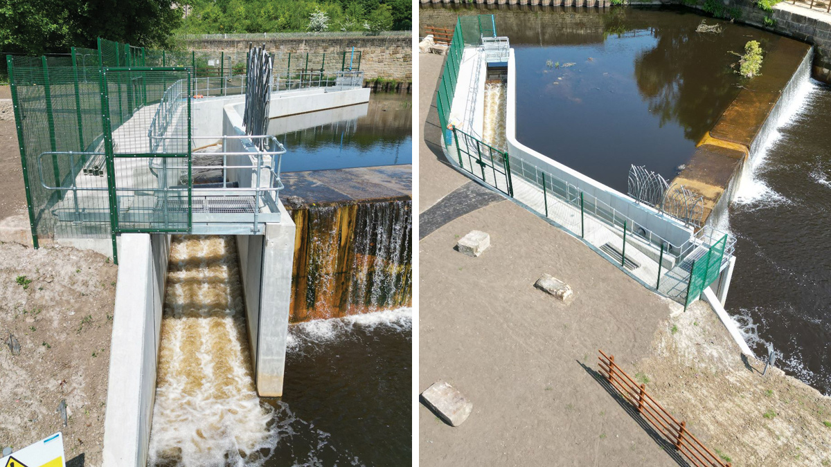
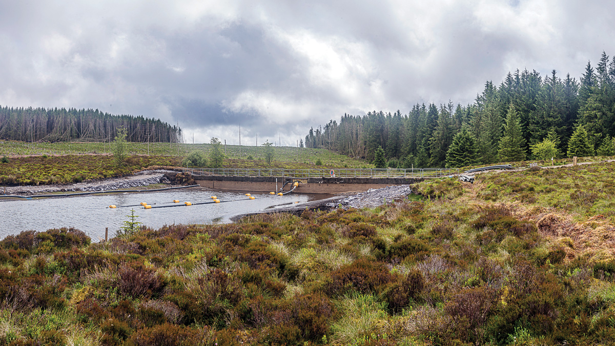
Four blockstone pre-barrages step water levels to allow fish passage, with adjacent ground lowering to increase flood capacity.
Landscape planting and public realm enhancements, including nearby Bonllwyn Green and the Llandybie Community Woodland Project.
Ecological enhancements for otters, bats, birds and invertebrates, focussed on improving connectivity, diversity and ecosystem resilience.
Reducing flood risk to homes and businesses
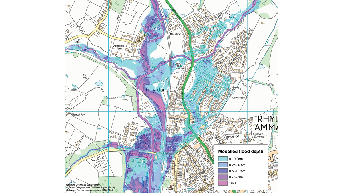
Ammanford is located at the confluence of the rivers Loughor, Lash and Marlas. The rivers respond rapidly to rainfall and their channel capacity is limited. Much of the town is built on low-lying land adjacent to the river and overtopping is predicted at multiple locations. If nothing was done to reduce flood risk, 198 homes and 25 business would remain at risk of flooding from the 1 in 100 (1%) annual chance event.
NRW studies demonstrated a strong case for change. The study area was one of the top communities at risk of flooding from main rivers within Western Wales, and facing one of the largest increases in flood risk as a result of climate change. Flooding in the area was predicted to cost the UK some £7.9m in today’s prices over the next century.
With options to slow flows upstream infeasible, optioneering focused on better containment of flood waters in the river corridor. No single flood defence would be able to meet the project objectives, so a combination of raised defences throughout was adopted as the preferred solution.
The scheme was designed to reduce flood risk up to the 1% AEP event, allowing for the impact of climate change over the scheme’s 100-year lifetime; benefiting 349 homes and 37 businesses.
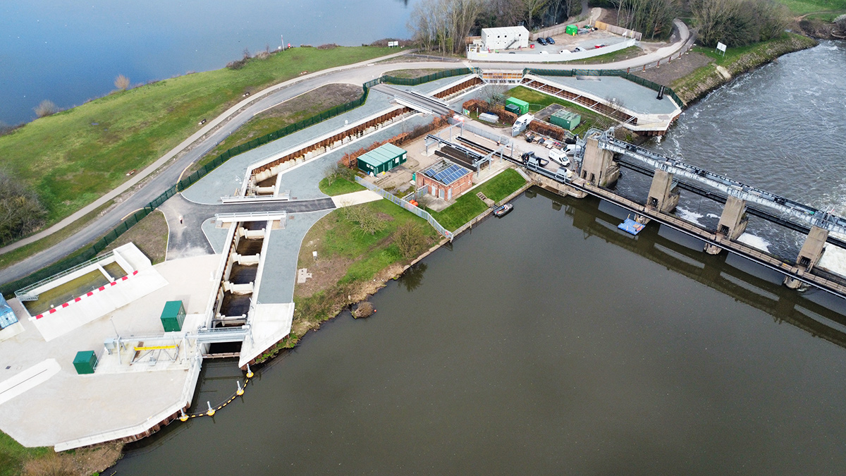
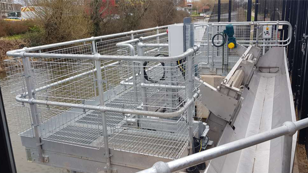
[caption id="attachment_14722" align="alignnone" width="1200"] (left) Project overview - Courtesy of Arup and (right) fish passage with adjacent ground lowering works - Courtesy of Walters[/caption]
Improving fish passage
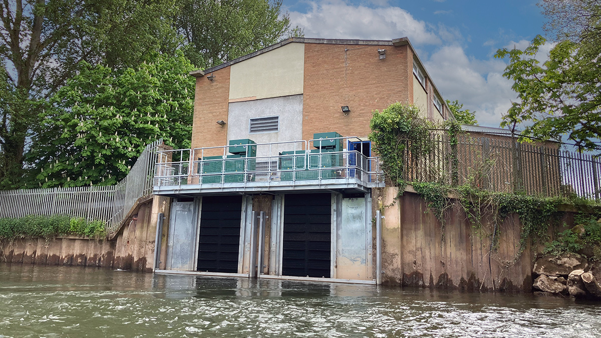
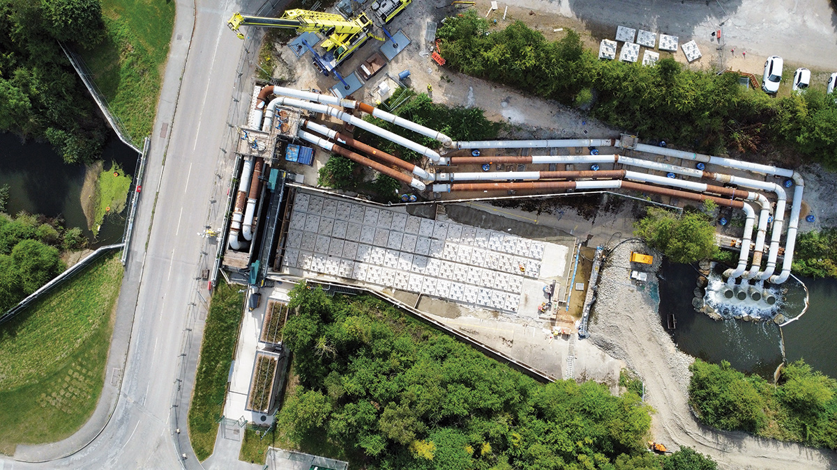
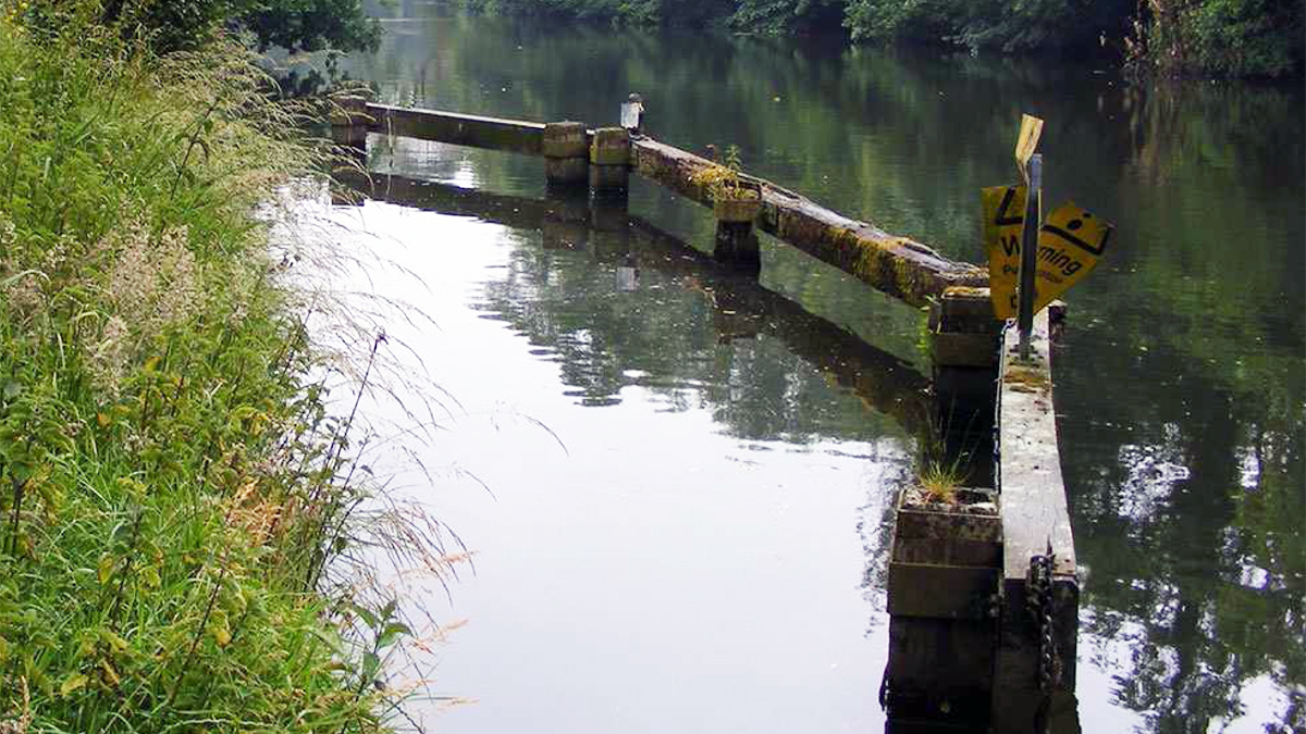
Separately, NRW had identified the case for improvements to Tir-y-Dail weir at the downstream extent of the scheme. The weir was a partial barrier for upstream migration of adult Atlantic salmon and trout, and a complete barrier to adult lamprey and juvenile European eel. Fish passage improvements would unlock 20km of river to migratory fish. The weir was in poor condition but encased a critical main sewer and enabled upstream river level gauging.
Scheme design and innovation
The design phase of the scheme involved comprehensive investigations and modelling to understand flood dynamics and identify effective solutions. Key design considerations and innovations are presented below.
Positive solutions to mitigate detriment
At the outset, the team identified a risk of conflict between the initially separate fish passage and flood scheme objectives. A further challenge was mitigating potential flood detriment to other areas. Flood modelling indicated that raising flood defences and making fish passage improvements to the Tir-y-Dail weir would cause unacceptable detriment elsewhere. Typical measures to mitigate the detriment were investigated but were found to be either ineffective or excessively costly (such as additional raised defences upstream) jeopardising the business case justification for the scheme.
The team identified and developed from first principles an innovative solution to locally address issues in proximity to the weir, including an area of ground lowering within the field adjacent to the existing weir and fish passage pre-barrages. This provided additional conveyance around the existing weir and proposed pre-barrages in more extreme flood events, mitigating potential detrimental increases in flood risk associated with both the flood defence and fish passage improvements.
To maximise the benefits of the ground lowering, soils generated from this area were used within the construction of the Tir-y-Dail flood bund, improving the scheme’s earthworks balance and reducing import volumes. The area was also landscaped to provide additional area of riparian habitat.
Balancing earthworks
Two factors made creating an earthworks balance on the project challenging. Firstly, the nature of the scheme and site constraints resulted in limited areas of fill. Secondly, the engineering and chemical parameters of some of the soils excavated were unfavourable.
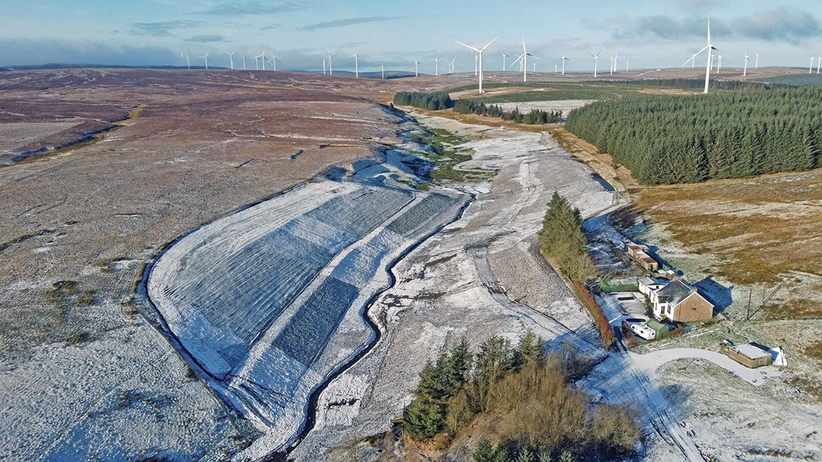
[caption id="attachment_14724" align="alignnone" width="1200"] Tir-y-Dail flood bund following construction - Courtesy of Walters[/caption]
To minimise the volume of excavated soils that would need to be disposed of off site, the team first addressed the chemical properties of the made ground. Site-specific risk assessments were undertaken to derive appropriate re-use criteria for human health and controlled waters. These were developed into a material re-use strategy, which considered appropriate legislative frameworks and was able to demonstrate that the majority of made ground was chemically suitable for re-use in appropriate scenarios.
To address the imbalance in volumes, the design of the Tir-y-Dail flood bund was reviewed as the primary fill area within the scheme. Flood bunds are most commonly constructed from a homogenous clayey material. This would need to be imported due to a lack of suitable on-site sources. The flood bund was therefore designed to have a ‘cap’ of imported clay to ensure performance against flooding, while the main core was formed from variable site-won material. Slope stability assessment undertaken under various scenarios demonstrated that, as long as the clay cap material was appropriately controlled, the geotechnical parameters for the core material could be significantly reduced.
To allow the contractor flexibility of the site-won materials placed in the core of the bund depending on the sequencing of their works, a project-specific soil material class was created. This was based on a combination of observational and basic material classification controls. This approach resulted in a reduction of 270 wagon loads of soil movements, reducing carbon and impact on local residents.
Sensitive detailing of flood defences
Measures were adopted to ensure the flood defences were sensitively integrated into the local landscape.
Flood walls in publicly viewable areas were finished with brick cladding, form liner finish and imitation stone copings to match local architecture. Coping stones were designed to be structurally integral to the flood wall to minimise their overall height, as well as reduce maintenance and public safety risk. Pillar features were incorporated into the facing of brick cladding at regular spacings to provide visual interest along the expanse of the wall.
[caption id="attachment_14725" align="alignnone" width="1200"] (left) Lightweight shuttering utilised in constrained working corridors and (right) brick cladding works to flood walls - Courtesy of Walters[/caption]
Design of the Tir-y-Dail flood bund was tailored to mitigate its impact on the open views from a nearby public right of way. In plan, a curved alignment was specified to conserve an irregular field pattern. In section, slopes were slackened and rounded at the top and bottom to create a naturalistic landform.
A fundamental element of the scheme design was determination of the alignment and form of the flood defences to minimise tree loss along the riparian corridor. An arboriculturist, who was integral to all major design decisions, was embedded within the design team. Every tree was considered individually so that as many trees as possible could be maintained. The resulting designs/design adaptations included micro-siting of flood walls and localised modifications to flood wall foundations in the vicinity of root protection zones.
Ammanford Flood Risk Management: Supply chain - key participants
Designer & ECC project management: ARUP
Design sub-consultant: FiskTek Consulting
Main contractor: Walters UK Ltd
Environmental consultants: Yellow Sub Geo
Ecology: Sylvan Ecology
Arboriculture: Mackley Davies Associates
Coping stone design: Quad Consult
Floodgates: MM Engineering
FRC works: Trueform Civil Engineering Ltd
Waterproofing: Tywi Damp Proofing Treatments
Metalwork: Cambrian Foundry
Reinforcement: Express Reinforcement
Asbestos disposal: Gavin Griffiths
Brick & stonework: JW Masonry
Surfacing: Laymak Ltd
Rail contractors: Protech Infrastructure
Rock armour: Tarmac Ltd
Landscapes: Afan Group
[caption id="attachment_14728" align="alignnone" width="1200"] Visualisation of Bonllwyn Green pocket park - Courtesy of Arup[/caption]
Nature and people thriving together
The project is in the heart of Ammanford, with interventions required in a combination of residential, commercial and public spaces. Multiple rounds of public engagement supported the scheme development, including:
Public drop in events with questionnaires on specific issues and feedback forms.
Online consultation during Coronavirus period, as well as letterbox information drops to ensure all parts of the community were engaged.
Regular newsletters, press releases, social media updates and a project website were provided throughout the design and construction phase of the scheme.
For public realm enhancements to Bonllwyn Green, visualisations and schematics were prepared to effectively communicate the scheme proposals and help local residents have their say on the design.
In line with NRWs strategic objectives, enhancements to public space and ecological habitats were fundamental to the scheme design, in addition to reducing flood risk. To provide biodiversity net benefit through increasing connectivity, diversity and ecosystem resilience of the high value riparian corridor, enhancements delivered as part of the scheme included:
Improved fish passage for multiple species through the existing weir on site.
Otter ledges beneath two existing road bridges.
Log piles for invertebrates, hedgehog nesting boxes and bat and bird boxes.
Where tree loss was unavoidable, they were replaced at a ratio of 3:1. Appropriate native species of local provenance and were designed to maintain and enhance habitat connectivity, while maintaining an appropriate amenity setting for the local community.
[caption id="attachment_14721" align="alignnone" width="1200"] Heol Hayden public realm improvements - Courtesy of Walters[/caption]
Improvements to public spaces in the vicinity of the flood defence works, but also within the wider community, were also delivered as part of the scheme as summarised below:
Where flood defences were constructed in public spaces and within the local college, the surrounding areas were enhanced with additional trees, swathes of bulb planting and new seating areas. Timber from trees felled as part of the scheme was reused to construct new benches.
At the Heol Hayden Flood Wall, the need for improved delineation of space between an existing riverside footpath and the adjacent gardens which fronted directly on to it was identified through community engagement and the Landscape and Visual Appraisal. A new hedgerow with small clusters of trees better defined the space and provided additional privacy to the local residents.
The existing Bonllwyn Green Park in the heart of the town was enhanced offering an amenity for local residents. The parks existing features were kept, but the space enhanced through avenue planting of specimen trees; drifts of bulb planting; interpretation boards; seating areas and informal play features formed from trees felled as part of the scheme.
As part of the scheme, NRW worked in partnership with Carmarthenshire County Council to deliver the nearby Llandybie Community Woodland Project, which comprised1.58ha of community broadleaved woodland with public access.
Protecting the environment
Environmental impacts were assessed through the Environmental Constraints and Opportunities Record (ECOR), with mitigation and enhancements integrated at an early stage into scheme development, heavily influencing the design process. Potential impacts upon trees, protected species, local community, archaeology, and local landscape, are some of the many that were assessed and mitigated.
The ECOR informed the Environmental Action Plan which formed part of the works information for the scheme and enabled key environmental mitigation measures to be communicated and tracked during the construction phase. The mitigation and protective measures implemented were comprehensive, covering the local community, protected species and environmental quality.
[caption id="attachment_14723" align="alignnone" width="1200"] Llandybie community woodland project - Courtesy of NRW[/caption]
Considerate construction
The works were spread across nine locations in Ammanford comprising residential, commercial and public areas. Each location presented unique challenges and constraints. To ensure that the project was executed safely and efficiently, significant effort was made to tailor methods of construction in each location.
The team’s focus on careful planning and attention to detail ultimately resulted in the successful completion of the project.
Early contractor investigation works captured potential clashes with existing utilities and structures. A collaborative working approach from all parties ensured potential issues were rectified before the main construction works commenced.
Working methodology, plant and equipment choices were tailored to the environment at each location to minimise disturbance. Due to the nature of restricted access in some locations, alternative construction methods were implemented. This included the use of a lightweight shuttering system that could be safely manually handled into position.
Collaborative working between the client, contractor and designers allowed early access for in-river works. Note only did this result in the fish passage works being completed with minimal impact on the ecosystem, but also reduced the overall construction programme by many months.
Summary
The Ammanford Flood Risk Management and Fish Passage Scheme is a testament to the importance of comprehensive planning, innovative design, and community involvement in flood risk management. By addressing the unique challenges of Ammanford, the scheme significantly reduces the flood risk for hundreds of properties and unlocks 20km of river to passage, as well as providing numerous other environmental enhancements. This case study highlights the critical role of such projects in building resilient communities and enhancing the environment.
The scheme was successfully tested whilst still under construction in September 2023.
[caption id="attachment_14726" align="alignnone" width="1200"] Flood event in September 2023 - Courtesy of Walters[/caption]