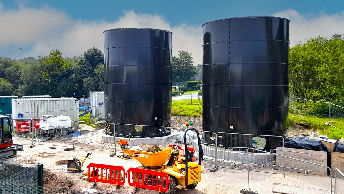
Kilkenny City Regional Water Supply ...
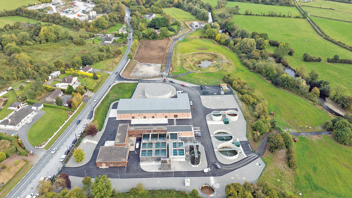
The Kilkenny City Regional Water Supply Scheme (RWSS) provides potable water to the population of Kilkenny City and its surrounding areas. The scheme had historically relied on multiple raw water sources, including the Radestown Water Treatment Plant (WTP) and the River Nore intake system. With increasing population demands, stricter regulatory requirements, aging infrastructure and the inability of Radestown WTP to remove THM precursors in the form of dissolved organic carbons from raw water sources, Uisce Éireann, in collaboration with Kilkenny County Council, identified the need for a major, €25m upgrade to ensure resilience, compliance, and capacity enhancement of the supply scheme.
Objectives
The primary objectives of the Kilkenny City Regional Water Supply Scheme Upgrade Project included:
Decommissioning of aging water sources and intakes.
The construction of a new raw water abstraction system upstream of Troyswood Weir.
A complete process and hydraulic upgrade of the Troyswood Water Treatment Plant (WTP) to meet a design capacity of 17.56 million litres per day (MLD) of treated water over an 18-hour operational window.
The upgrade integrates enhanced treatment processes, a robust disinfection strategy, and advanced automation and control systems to ensure high-quality drinking water delivery well into the future. A detailed description follows.
Kilkenny City Regional Water Supply Scheme: Client, delivery contractor & designers
Client: Uisce Éireann
Design & build contractor: Glanua Group
Main consultant: Ryan Hanley
Civil & structural designer: Jennings O’Donovan
Pipework support design: Construct Engineering
Cofferdam design & supply: Trench Control
New raw water intake works
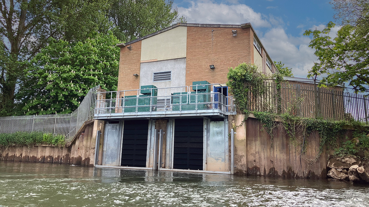
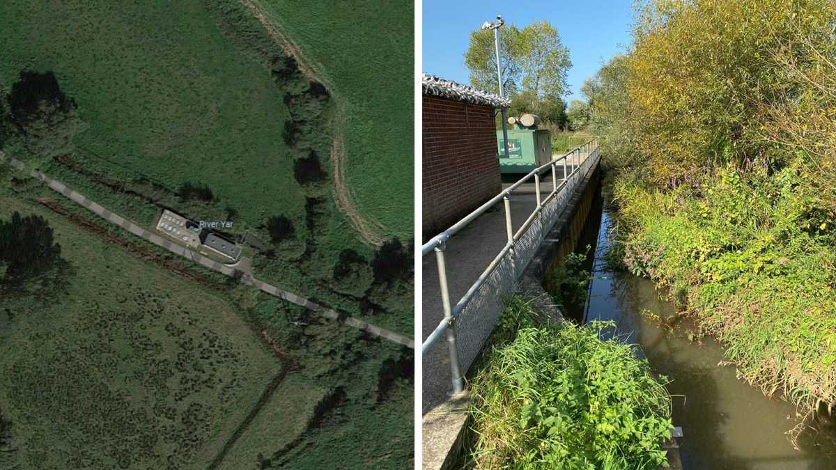
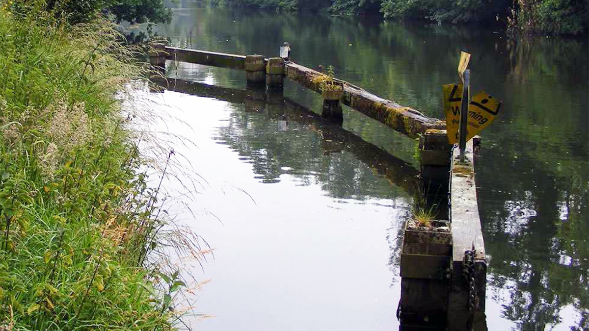
To replace the decommissioned Radestown WTP and existing River Nore intake, a new intake structure was constructed 70 metres upstream of Troyswood Weir to ensure water was abstracted from a less turbulent part of the river. Raw water is abstracted from the River Nore at a maximum rate of 1031.6m3/hr for a max duration of 18hrs /day to adhere to the current abstraction license.
[caption id="attachment_21878" align="alignnone" width="1200"] (left) Raw water intake under construction, (top right) the Beaudrey raw water inlet screen, and (bottom right) the completed structure - Courtesy of Glanua[/caption]
Water enters the intake structure through a 25mm coarse bar screen installed on the face of the intake structure which is aligned diagonally at a 45⁰ angle counter current to the river flow to facilitate a sweeping and self-cleaning passage of floating river debris off the coarse bar screens.
A sedimentation channel was constructed downstream of the coarse screen. This allows any large solids to settle out before reaching the end of the channel and entering a mechanical fine screen. The width was calculated to allow a max velocity of 0.15 m/s at max design flow allowing any fish that enter the sedimentation channel to swim against the current and back into the River Nore.
Raw water sampling is carried out immediately after the coarse screen via two duty/assist sample pumps feeding back to a local sample instrumentation board in the raw water building. Having the board situated locally significantly reduces lag time in real time sample results ensuring any exceedances in raw water parameters are detected immediately and pumping to the treatment process is inhibited.
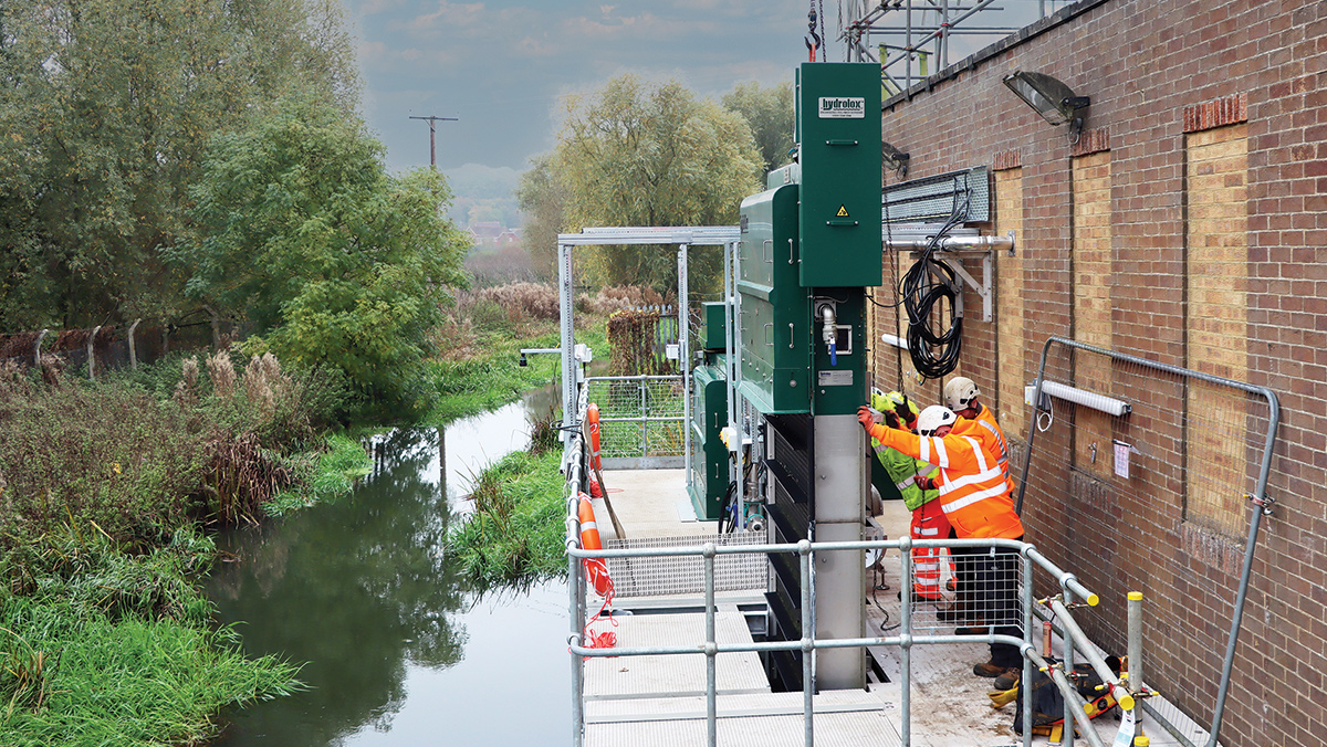
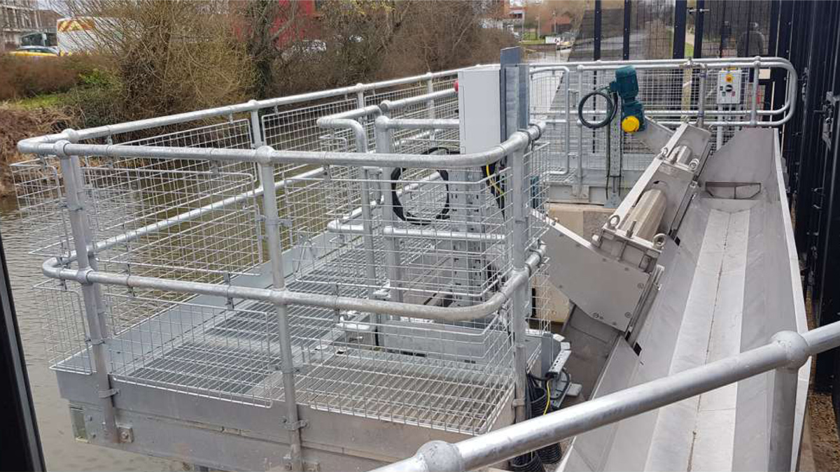
At the end of the settlement channel, a Beaudrey mechanical screen was installed with a ‘catch and return system’ which is fitted with a spray bar and fish buckets providing fish, eel and elver protection with respect to both impingement and entrainment.
Troughs on a moving screen lift any debris and fish out of the water. A low-pressure jet removes the fish and loose debris from the trough and into the fish return launder and back to the river.
[caption id="attachment_21865" align="alignnone" width="1200"] Inside the raw water intake building - Courtesy of Glanua[/caption]
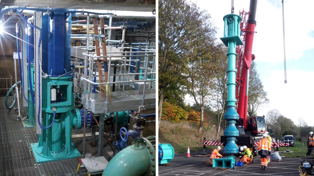
Once the trough passes through the low-pressure system it is then hit with a high-pressure jet, dislodging any debris and materials from the 3mm mesh. This water returns to the river in the debris launder. Water for jetting is provided via submersible pumps downstream of the fine screen. The screen is operated continuously to ensure no fish are trapped in the sedimentation channel for a prolonged period. After passing through the mechanical fine screen the raw water is pumped to the treatment process via a newly installed rising main by three 65kW duty/assist/standby pumps fitted with vibration/temperature monitoring to ensure the system is operating to maximum efficiency.
Kilkenny City Regional Water Supply Scheme: Subcontractors
Mechanical installation: CPE (Callan Precision Engineering)
Electrical installation: Cross Electrical
Automation: UMAC
Precast concrete structures: Carlow Tanks
Precast process tanks & chemical building walls: Shay Murtagh Precast
Insitu concrete works: Raps Construction Limited
Drilling & trenchless crossings: Dunnes Drilling Services
Pipeline & cofferdam Installation: Lixnaw Plant Hire
Flocculation tanks: Irish Industrial Tanks
Covers: Manhole Covers Ireland Ltd
Scaffolding contractor: Galtee Scaffolding
Fencing: Brennan Fencing
Stone & concrete: Kilkenny Block
Fireproofing: Fitzpatrick Insulation & Passive Fire Protection
Structural steel portal frame: Goggin & Buckley & Co
Sludge farm structural steelwork: Southwest Engineering
Landscaping: Slievenamon Landscaping
[caption id="attachment_21863" align="alignnone" width="1200"] Raw water dosing culvert - Courtesy of Glanua[/caption]
Process upgrade at Troyswood WTP
The Troyswood treatment plant is made up of three areas:
Chemical building: This houses the chemicals associated with the process along with the high lift pump room and sludge room.
Existing water treatment plant: The existing water treatment plant includes the clarification and filter processes, low lift pumping, and UV treatment; 5-log removal of cryptosporidium is required to adhere to the project specification (3 log removal is provided via the coagulation, flocculation, clarification (CFC) and filtration stage, with the remaining 2-log removal achieved by UV dosing).
Clear water tanks & reservoirs: Low lift pumping sends filtered water through the UV treatment plant and on to the clear water tank where it is stored before being pumped to the Radestown and Thornback Reservoirs.
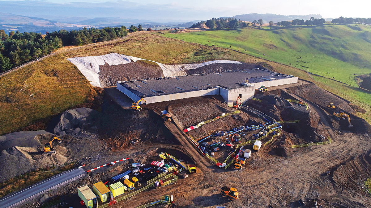
Sludge farm: A new residuals treatment system was also built to manage washwater and sludge:
Used washwater equalisation and settling tanks.
Sludge thickening and holding tanks.
Sludge dewatering room.
A critical element of the upgrade works was to ensure the existing plant remained operational and consistently maintained customer supply. This was achieved with extensive planning and collaboration with Glanua Group’s Operational Department and other stakeholders adding to the success of this project.
[caption id="attachment_21870" align="alignnone" width="1200"] New sludge farm - Courtesy of Glanua[/caption]
Chemical pre-treatment & flocculation enhancements
A new chemical and treated water pumping building was constructed to house storage and dosing systems for pre-treatment chemicals including:
pH/alkalinity suppression agents.
Coagulants for enhanced coagulation aimed at reducing trihalomethanes (THM) formation.
A new tapered flocculation system replaced the older configuration to accommodate the increased throughput, enabling improved particle agglomeration ahead of filtration.
Raw water enters the chemical building below ground. Inside the chemical building, the pipe is accessed by means of the raw water dosing culvert, where it is dosed with sulphuric acid to lower the pH to a target value suitable for coagulation using PACL 18%; dosed downstream of the sulphuric acid post-mixing. To save space and reduce the culvert size, two static mixers were used for each of the dosing setups.
Dosing is controlled by means of UVT bands. UVT is measured at the raw water instrumentation board. Based on process calculations, %UVT bands are given a dose rate for the two chemicals. This was fine-tuned at the commissioning stage and adjusted based on experience of conditions when operating the plant.
Raw water then enters two new flocculation tanks with a combined retention time of approximately 30 minutes at design flow. Here, poly-electrolyte is added to water via a sparge bar at the top of the tanks. The water is mixed in Tank 1 at ~15 RPM before passing onto Tank 2 where it is mixed at ~10 RPM.
On leaving Tank 2, water passes through an existing mixing chamber now denoted as Flocc Tank 3. Poly-electrolyte dosing and gradually reduced mixing in addition to the PACL 18% leads to flocc formation in advance of the settlement process in the clarifiers.
[caption id="attachment_21872" align="alignnone" width="1200"] Clarifiers - Courtesy of Glanua[/caption]
Hydraulic & process tank upgrades
Process tanks within the WTP were both hydraulically and mechanically upgraded to handle the full abstraction capacity from the new intake. The existing plant was made up of two flat bottomed clarifiers and three rapid gravity sand filters. To achieve the required throughput of the plant, the capacity of the clarifiers and filters needed to be increased. The contract also required that the full throughput of the plant could be achieved with 1no. clarifier and filter out of service. This is to allow for scenarios where tanks need to be taken offline for maintenance.
The existing system was reviewed in terms of capacity and hydraulics. Retrofitting the existing clarifiers with tube settlers and installing one additional clarifier allowed for the design throughput of 1031.6m3/hr while maintaining the maximum clarification rate of 6m/h. The additional tank was designed to be a replica of the existing cells. This ensured hydraulics matched over the three cells and ensured even dispersal of water across the three clarifiers.
Water enters the clarifier through lateral PVC pipework at the bottom of the tank before rising to meet the tube settlers. The tube settlers are supported on a stainless-steel frame with a hatch incorporated for future maintenance. The tube settlers encourage settlement of any solids that make it past the formed sludge blanket with clarified water exiting through the top and into launders that convey the water to a common clarified channel and on to the filters. Sludge is then drained off the clarifiers via a sludge bleed channel and eight pinch valves working sequentially on each clarifier.
Automatic time intervals are based on raw water UVT with higher UVT meaning closer intervals to ensure the clarifier sludge blanket is maintained at a constant depth and level.
[caption id="attachment_21876" align="alignnone" width="1200"] Upgraded clarifiers and filters - Courtesy of Glanua[/caption]
Filtration & disinfection improvements
Filtration capacity was increased by the addition of a new rapid gravity sand filter. To support higher filter backwash rates, the existing backwash pumps and air blowers were upgraded in accordance with IW-TEC-900-04 specifications. The existing clear water tank was reconfigured to act as both a filtrate water sump and backwash pump sump, reducing carbon footprint by reusing existing infrastructure.
A similar study of the filters to that of the clarifiers showed that N+1 flows could be achieved for the design flow by adding one filter and installing an under drain filter floor. This achieved capacity of 1/3 design flow through each filter, allowing one tank to be taken out of service if required. Again, the new tank was constructed to match the existing tanks to maintain similar hydraulics and ensure even throughput across the filters. Additional filter upgrades included increasing the backwash weir to allow expansion of the newly installed media. To avoid a prolonged shutdown of each filter, this was carried out by installing a prefabricated stainless-steel wall, allowing the install to be carried out over 2-3 days rather than waiting for concrete curing.
Filtered water enters an existing combined filtered water culvert and makes its way to the low lift sump. The low lift sump was originally the final clear water tank for the existing plant, including a backwash section by means of a dividing wall. However, due to sizing and increased throughput, this now became a break tank before water is pumped onwards via three 30kW duty/assist/standby pumps through the UV and into the newly constructed 2ML clear water tank.
In addition to the low lift pumps, two new 75 kW backwash pumps extract from this tank during the backwash phase of the filtration cycle and required the capacity of the whole tank, not just the existing backwash section. This meant that the tank needed to be hydraulically balanced with three cores carried out on the existing dividing wall, sized to allow design throughput of the plant. Further to this, the new backwash pipework was increased from DN300 to DN600 meaning very little space between the suction pipework and existing walls.
[caption id="attachment_21868" align="alignnone" width="1200"] Backwash (yellow) and low lift (blue) pump room - Courtesy of Glanua[/caption]
A detailed survey was carried out on the existing sump. This allowed the backwash and low lift suction pipework to be installed, and cores to be located, to prevent cavitation in the suction pipework. Part of the survey included cores to determine the existing makeup of the roof slab to allow design of the backwash and low lift pump support system.
The ‘brownfield’ nature of the works meant multiple and complex interfaces with the existing live water treatment plant while also ensuring treated water compliance at all times. These works included multiple shutdowns and confined space entries which required extensive planning and coordination with Glanua Group’s operations teams to ensure supply to the network was maintained at all times; a testament to the team that ensured the works were completed safely and within the allowable timeframe.
UV disinfection & multi-barrier strategy
The final part of the treatment process involves the transfer of water from the low lift sump to the clear water tanks via two duty/standby UV units; a calculated Dose UV System with real-time control minimising power requirements. This achieves the additional 2 log reduction for cryptosporidium, ensuring the 5-log total required. The UV units are validated to a minimum UVT of 80% which is monitored by a constant UVT reading from the low lift sump upstream of the UV dosing. The new UV system was added within an extension to the existing WTP building and included:
Duty/standby UV reactors with calculated dose approach.
Control panels for log inactivation compliance per Uisce Éireann’s Protozoal Compliance Criteria.
[caption id="attachment_21866" align="alignnone" width="1200"] Duty/standby UV arrangement - Courtesy of Glanua[/caption]
Post UV treatment, the water is dosed with sodium hypochlorite and hydrofluorosilicic acid before entering the clear water tank. The upgraded system implements real-time Ct calculation to verify chlorination effectiveness. PH adjustment is carried out by dosing sodium hydroxide 30% over the CWT inlet via a sparge bar. Orthophosphoric acid dosing takes place prior to high lift pumping to the Radestown and Thornback Reservoirs.
Treated water distribution
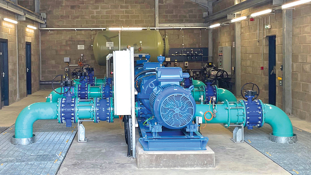
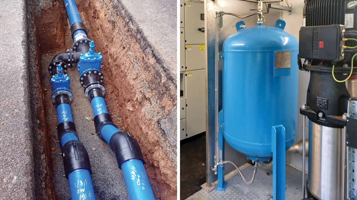
High lift pumping is carried out on a duty/assist/standby basis by five 75kW pumps conveying 8.78 MLD to each reservoir. To save costs, all high lift pumps for both reservoirs are located on a common manifold with one pump acting as standby for each reservoir. This pump can be swapped between each rising main by means of an actuated valve when required.
A new 2,980m DN450 treated water rising main was constructed to convey treated water to Radestown Reservoir with the existing rising main to Thornback retained, with valved tee connections enabling flexible operation. These changes ensure efficient delivery to both reservoir systems and form part of a robust dual supply strategy for Kilkenny City RWSS.
[caption id="attachment_21869" align="alignnone" width="1200"] High lift pump room - Courtesy of Glanua[/caption]
Residuals management & automation
A new residuals treatment system was also built to manage washwater and sludge:
Used washwater equalisation and settling tanks.
Sludge thickening and holding tanks.
Sludge dewatering room.
Two washwater settlement tanks take water from the filtration backwash process. Settled water is decanted to the river Nore with interlocks ensuring a maximum turbidity of 10NTU preventing any negative effects on the river and associated wildlife. Sludge is combined with clarified bleed sludge in a PFT where it is thickened before being stored and sent to a centrifuge for dewatering. Rationalisation of the specimen design allowed removal of two equalisation tanks by combining equalisation and settlement tanks and removal of a proposed sludge building by condensing the required infrastructure into a smaller setup that could be installed in the chemical building sludge room while still maintaining access for O&M requirements
SCADA upgrades were implemented across the site to allow real-time process control, Critical Control Point (CCP) monitoring, and automated alarm systems. The upgraded control system ensures consistent operation and provides remote monitoring capabilities.
Kilkenny City Regional Water Supply Scheme: Suppliers of process plant & materials
Raw water intake screen: Beaudrey
COLBERGE poly preparation unit: Bondalti Water Enkrott
Filter floors: Xylem Water Solutions
Control panels: Automated System & Control
Air-release valves: Alma Engineering Supplies
Pneumatic valves: AxFlow Ltd
Pinch valves: GEMÜ Ireland
Wedeco UV disinfection units: Xylem Water Solutions
Enexio tube settlers: Brentwood Europe Ltd
Compressors: Kaeser Kompressoren
pH & turbidity probes: Hach
Pump supplier: Xylem Water Solutions
Pipes & ducts: Fusion Pipeline Products (IRL) Ltd
Sulphuric acid tanks: FDK Engineering
Bulk chemical tanks: Forbes Technologies Ltd
Filter media: Irwins Quality Aggregates
Precast concrete roof slabs: Fogarty Concrete
Supply & Install of radon barrier: Michael Ormond Limited
Reinforcement: Coen Steel
Brickwork, insulation, wall ties etc: GW Blockwork
Supply & install of roof membrane: Kilkenny Asphalt
Concrete accessories: Anchor Bay Ireland
Concrete blocks: Kilkenny Block
Stone: Bennettsbridge Limestone
Brickwork: Acheson & Glover
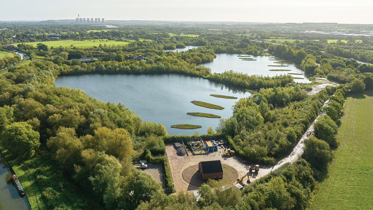
[caption id="attachment_21877" align="alignnone" width="1200"] View of the completed works from the new intake works - Courtesy of Glanua[/caption]
Innovations, carbon reduction & cost efficiency
The project adopted several forward-thinking solutions:
Enhanced coagulation and multi-barrier disinfection for regulatory compliance and public health protection.
Where feasible, existing assets were reused (such as the clear water tank, pipework etc), which reduced embodied carbon and construction costs.
The new Calculated Dose UV System with real-time control minimises energy use and enhances verification capacity.
Variable speed drives across pumping systems improve energy efficiency and enable dynamic control based on demand.
An attenuation pond captures any process overflows and promotes percolation before discharging to the River Nore.
Conclusion
The Kilkenny City RWSS upgrade represents a significant milestone in the modernisation of water infrastructure for the region. With construction and commissioning successfully completed, the scheme now delivers up to 17.56 MLD of high-quality potable water, meeting the latest Uisce Éireann regulatory standards and future-proofing supply to a growing population.
Lab analysis shows results of between 30-50 µg/l THM at both Thornback and Radestown Reservoirs, well below the recommended limit of 80µg/l which was one of the main drivers of the project. UVT of 90% is consistently achieved along with chlorine residuals and turbidity all in compliance.
[caption id="attachment_21871" align="alignnone" width="1200"] Tree planting to reduce loss of biodiversity - Courtesy of Glanua[/caption]
The Troyswood WTP was a brownfield site upgrade that more than doubled the original capacity of the treatment plant and added additional stages to the process to make the system more resilient. Installing the required equipment in the existing buildings and tanks, while operating and maintaining the current supply was a challenge for the Glanua Group team, but one that was ultimately successful. This is clear from the little to no interruption to supply during the install and the successful operation of the plant after commissioning.
Not only was the project technically successful, but it has also delivered on a sustainability level, with carbon footprint and cost savings achieved by the rationalisation of the design gaining efficiencies in many areas such as removal of an entire building and non-critical lighting along with utilising latest technologies and automation to reduce the amount and size of concrete tanks, and infrastructure required.
The integration of advanced process technologies, energy-efficient pumping solutions, and automation control systems ensures long-term operational resilience and environmental sustainability. Future upgrades and maintenance works can now be executed with minimal service disruption due to the built-in redundancy and improved system flexibility.
Project success was achieved by Glanua Group working closely with the key project stakeholders, Uisce Éireann and design consultants Ryan Hanley, in collaboration with Kilkenny CC where required. Ryan Hanley recently won an award under the category of Sustainability Natural Environment which was presented at the ACEI Awards on 4 April 2025.


