MGF Ltd
River Humber Pipeline Replacement
MGF Ltd
Scope of works
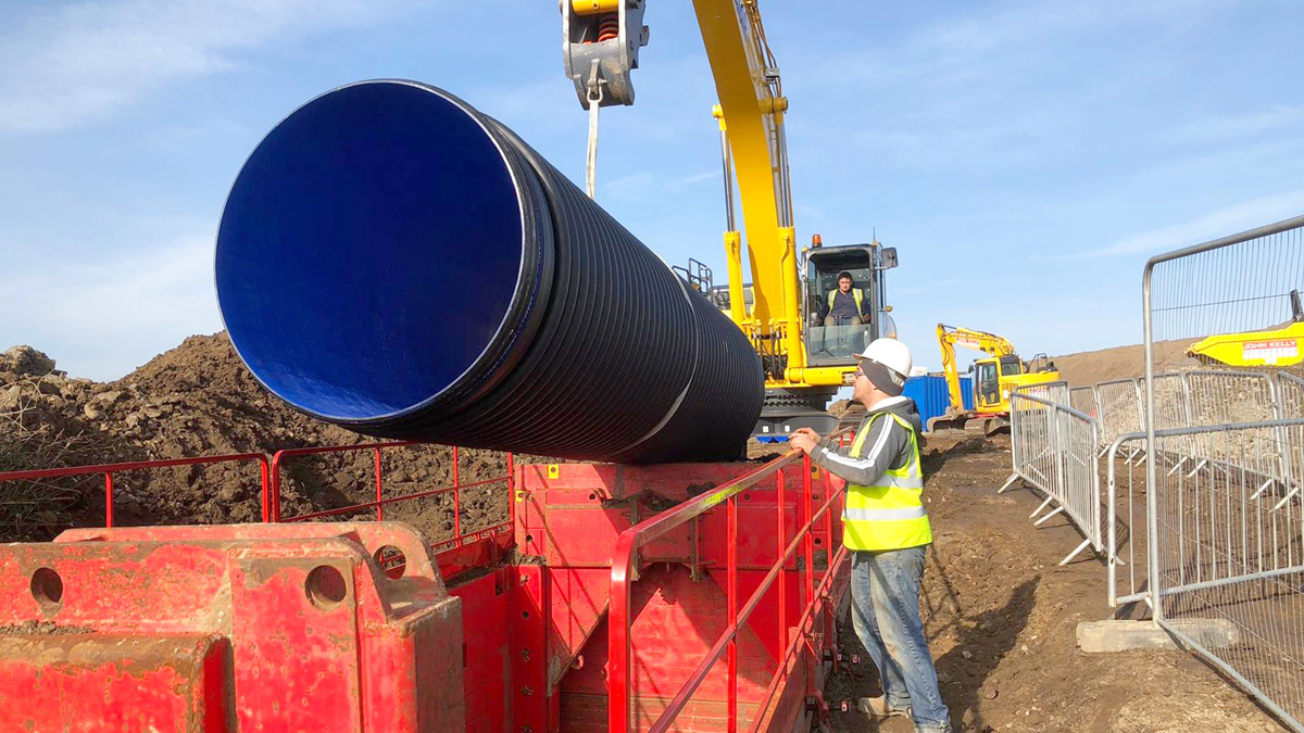
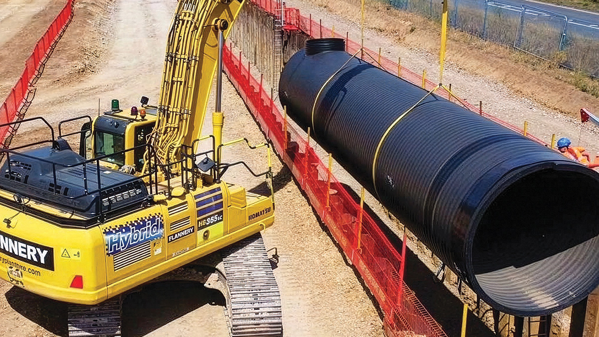
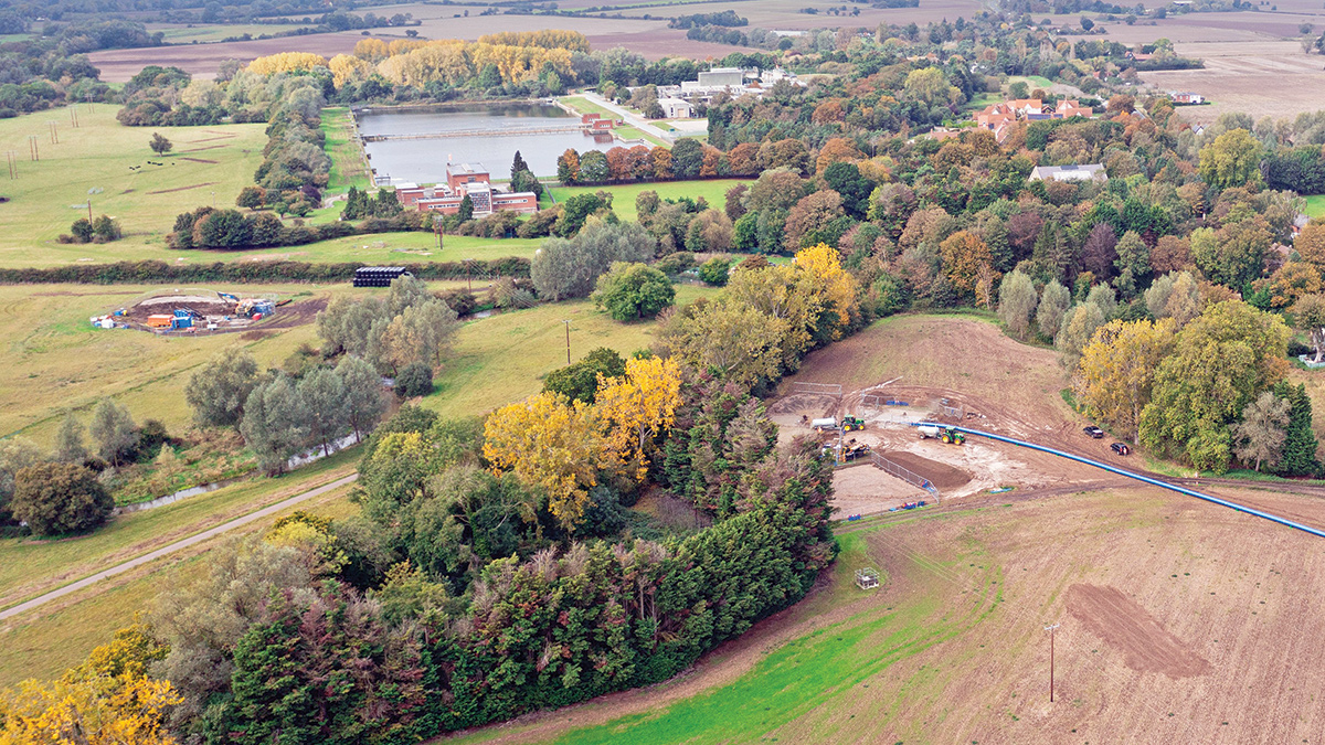
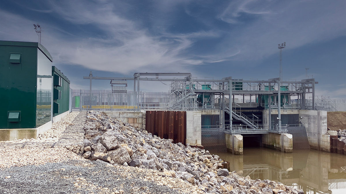
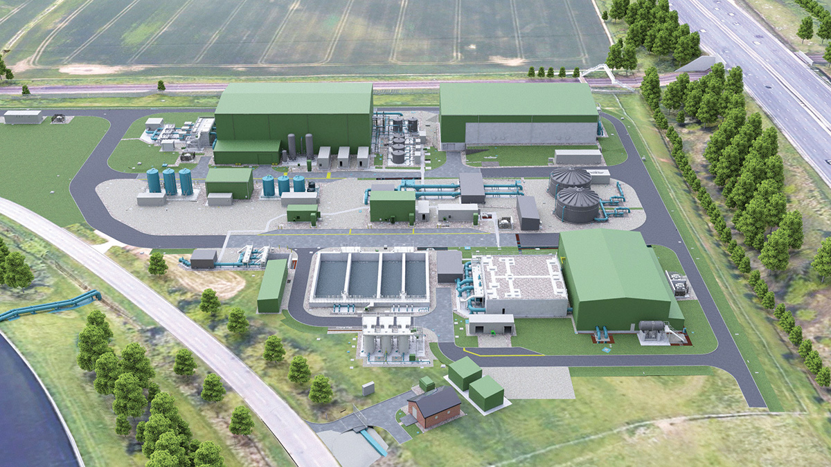
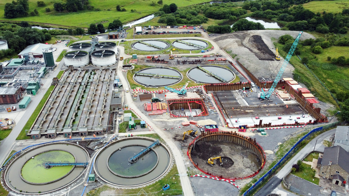
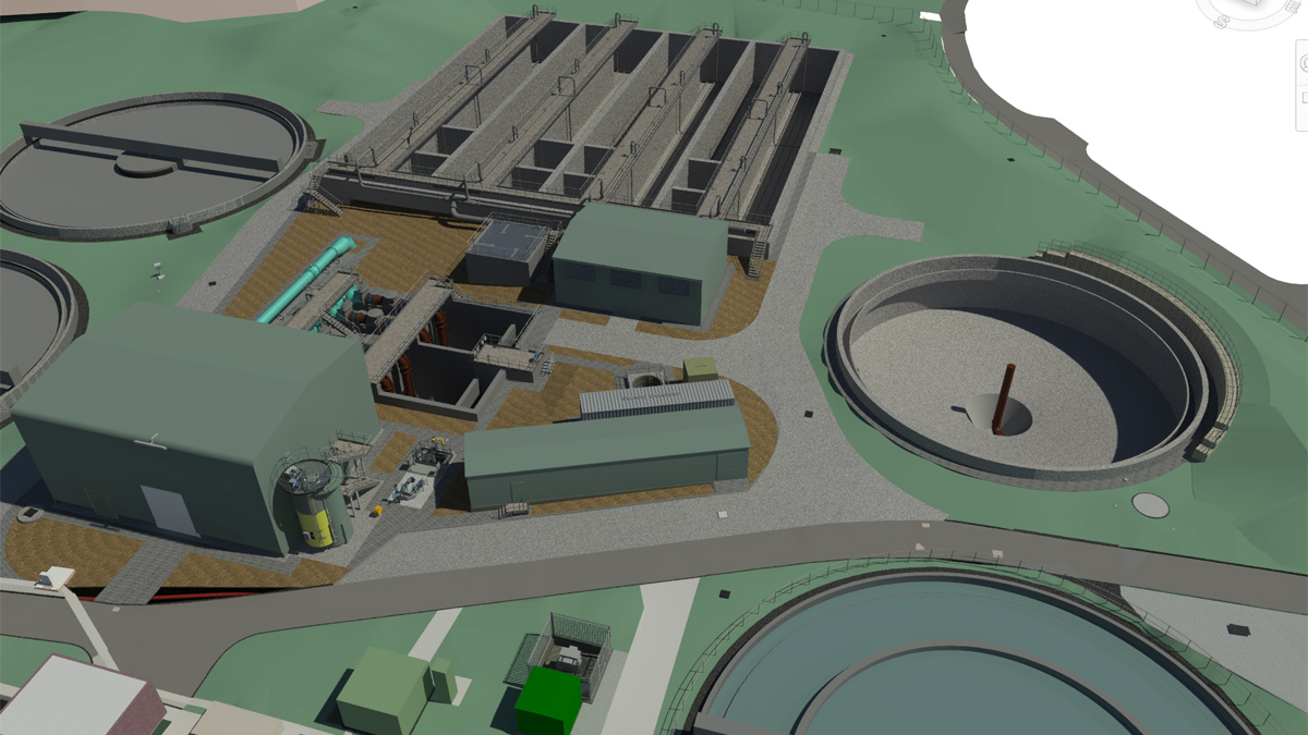
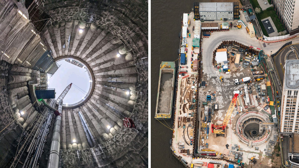
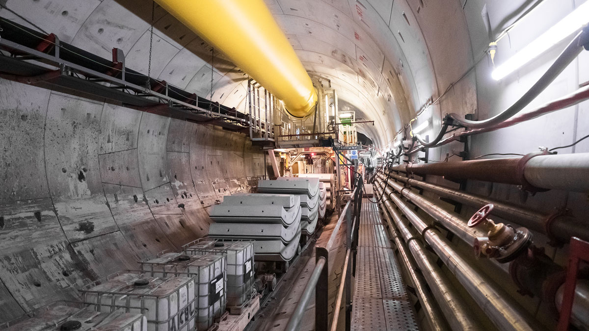
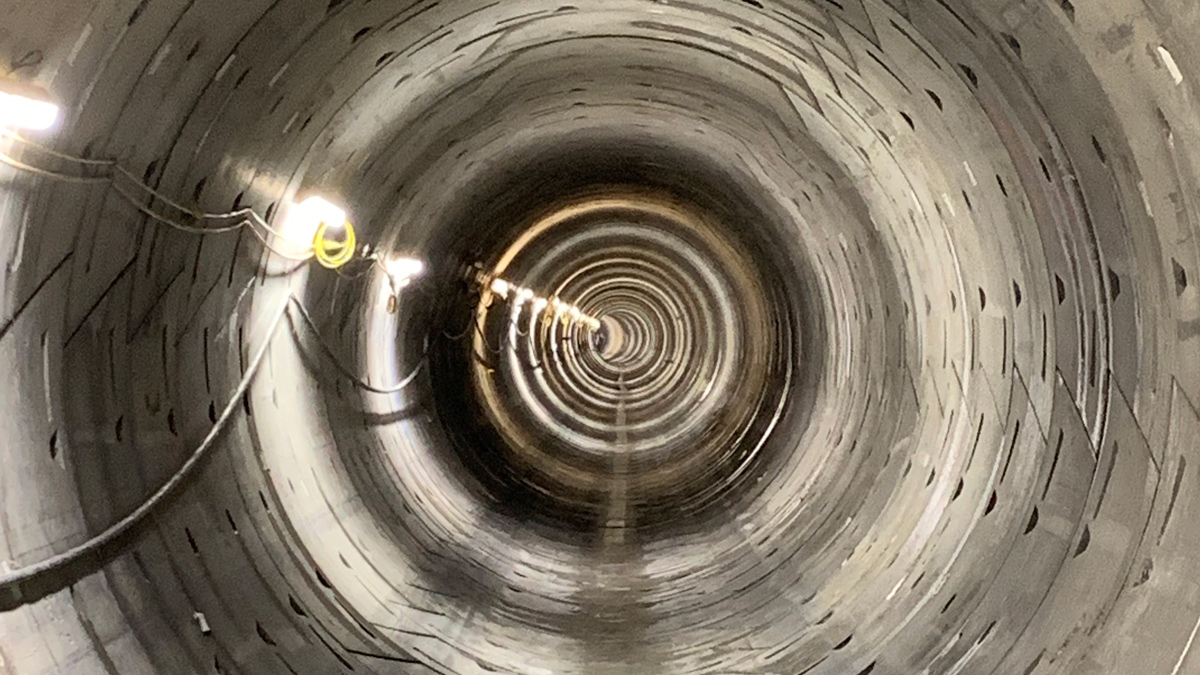
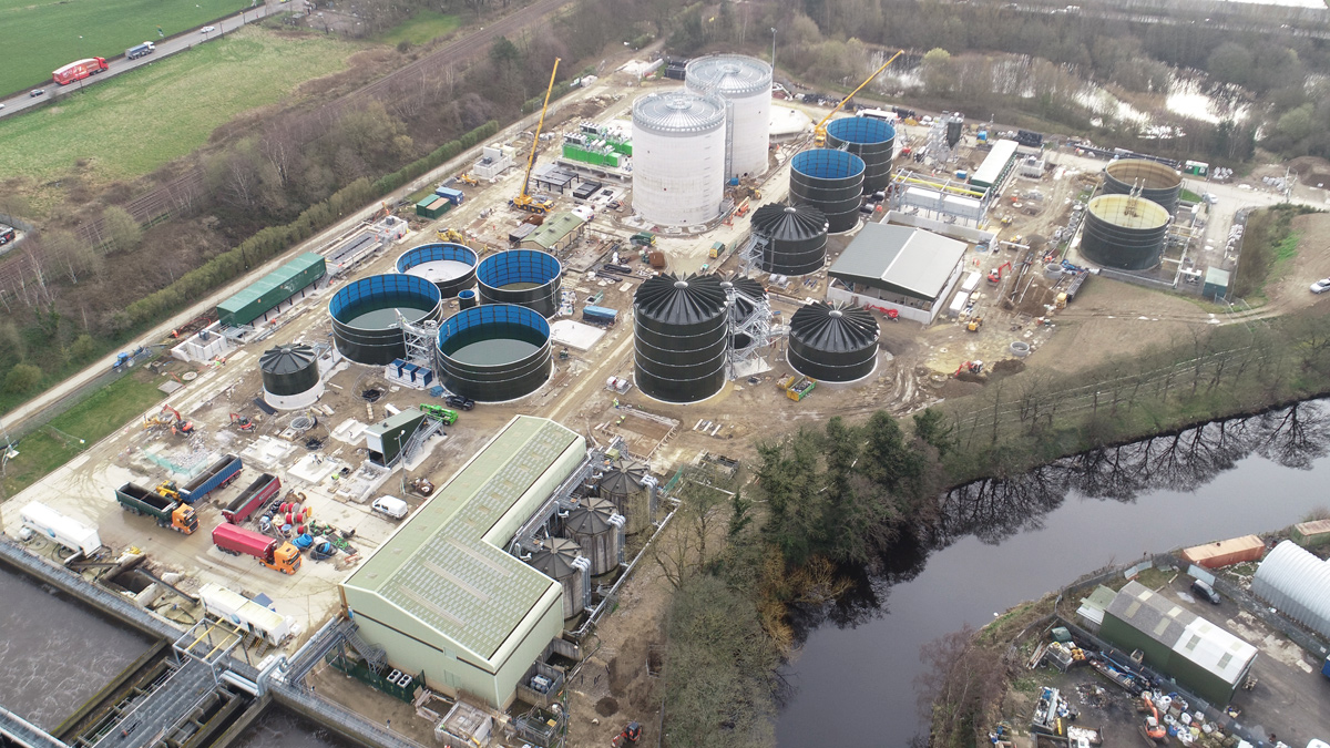
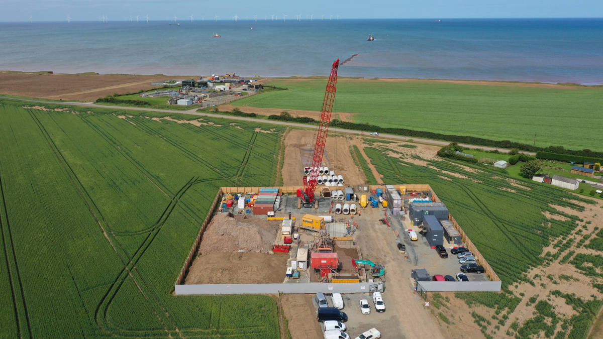
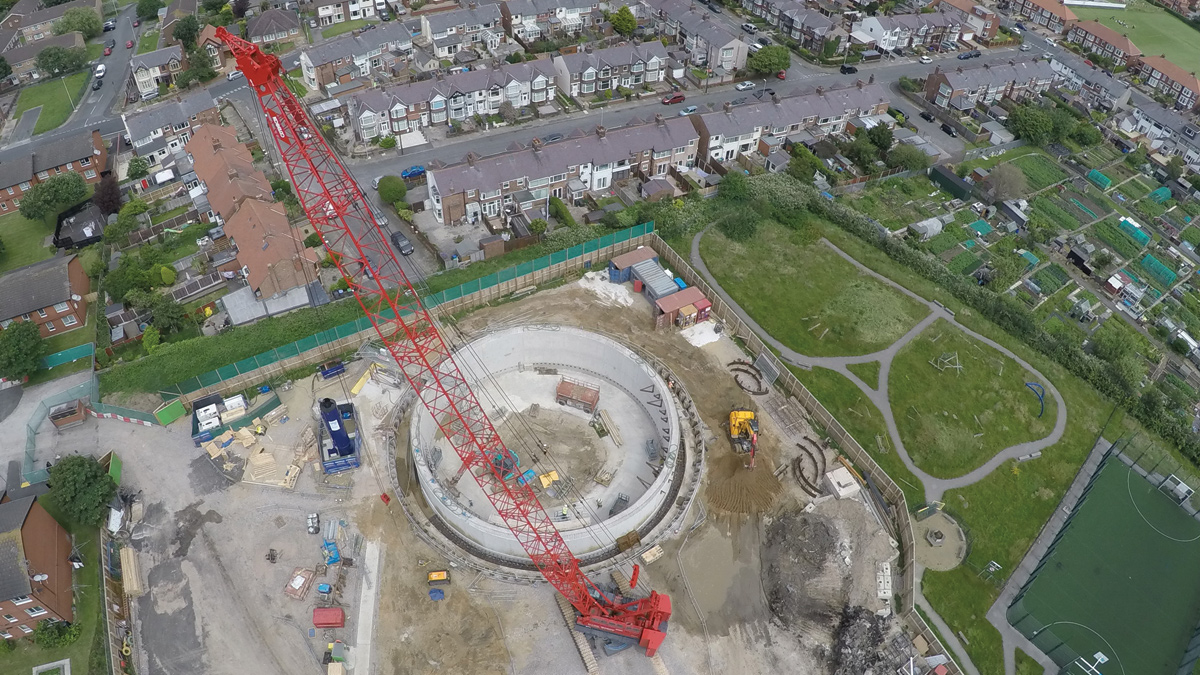
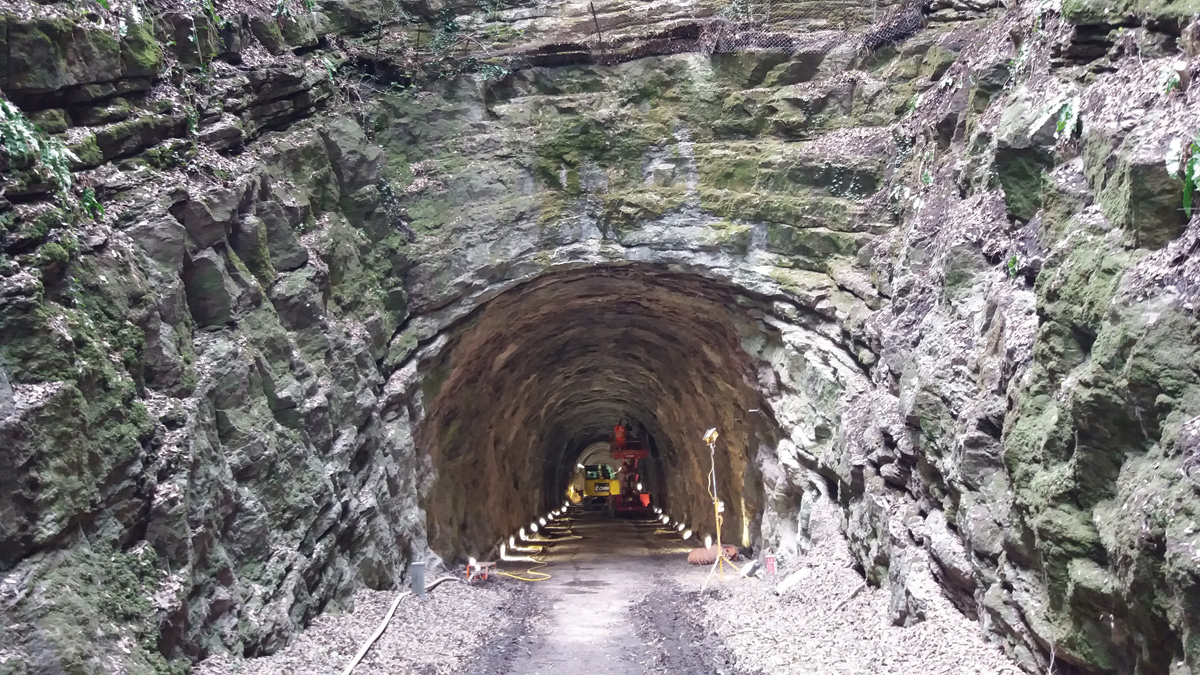
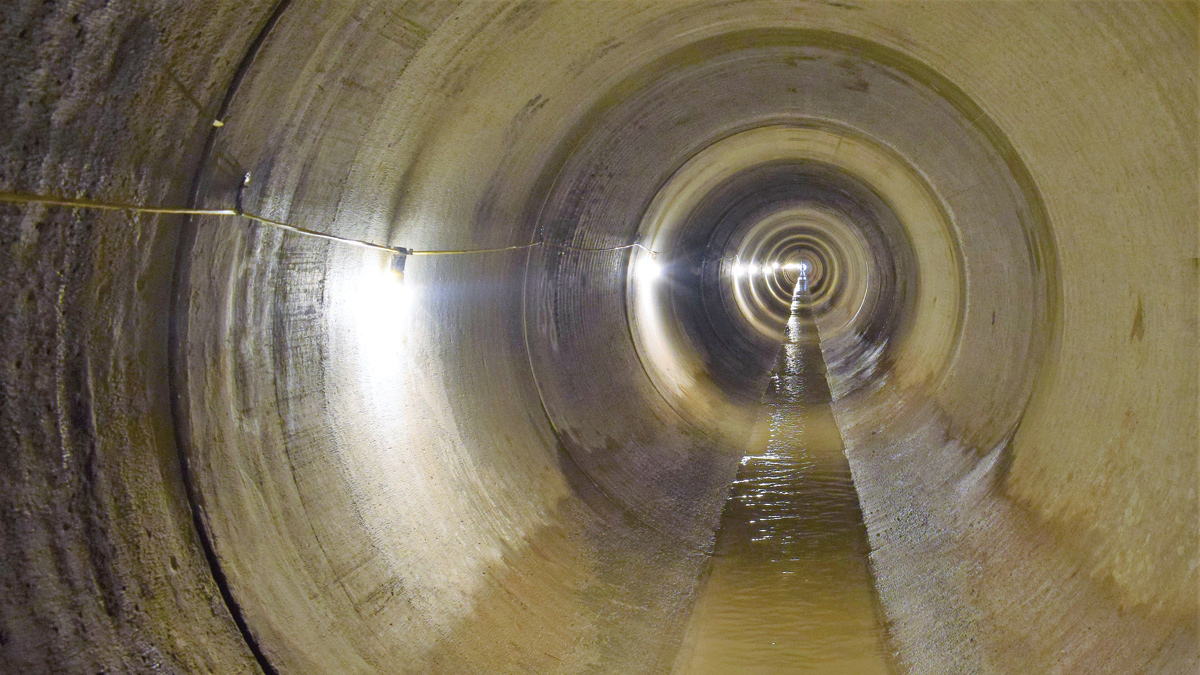
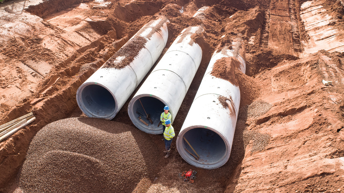
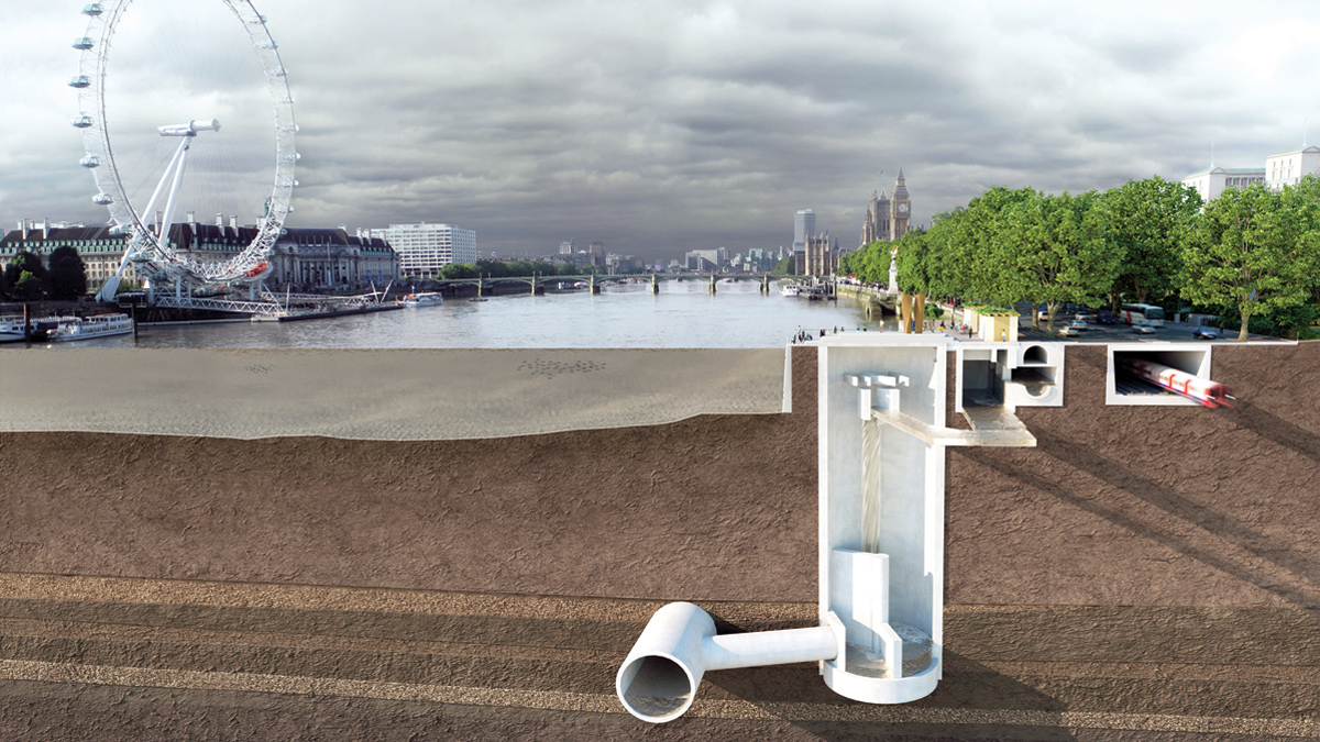
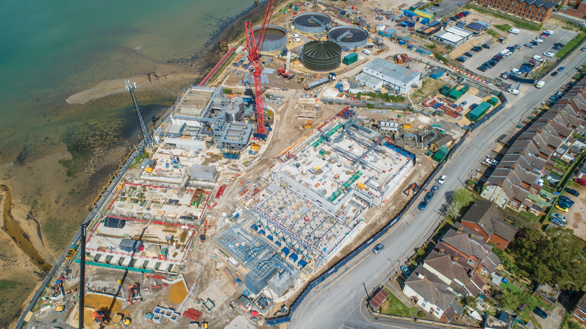
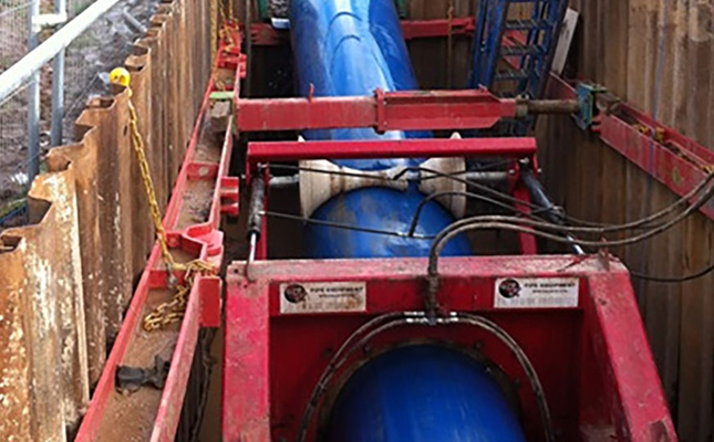
National Grid, working with North Lincolnshire Council and East Riding of Yorkshire Council, developed a plan to construct a tunnel under the River Humber to replace the existing pipeline. The three-year project will provide National Grid with a 5km long, 3.65m diameter tunnel bored 30m under the river bed. A single 1200mm concrete-weight coated steel pipe will be inserted into the tunnel in a single string, making it the longest gas pipeline insertion of this kind in the world.
Issues and solutions
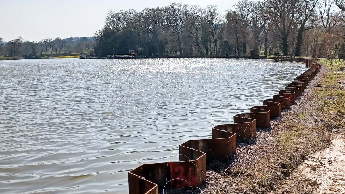
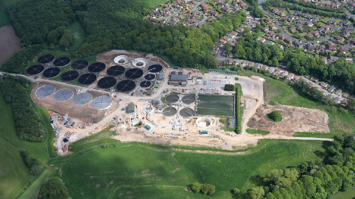
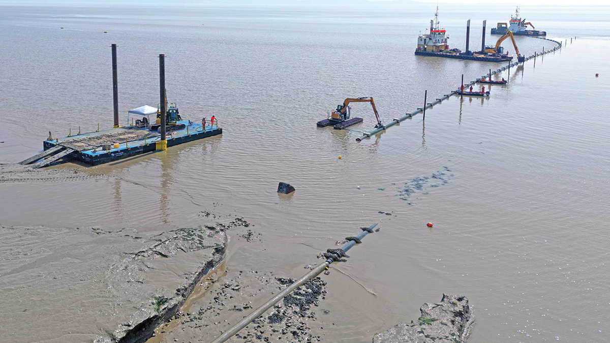
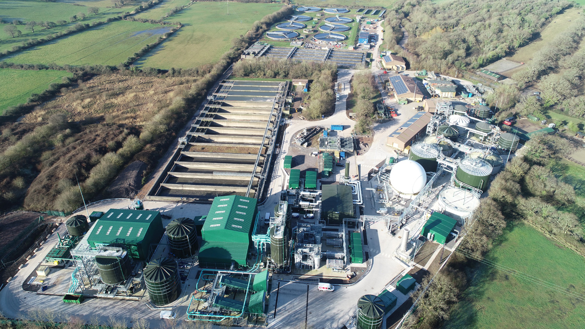
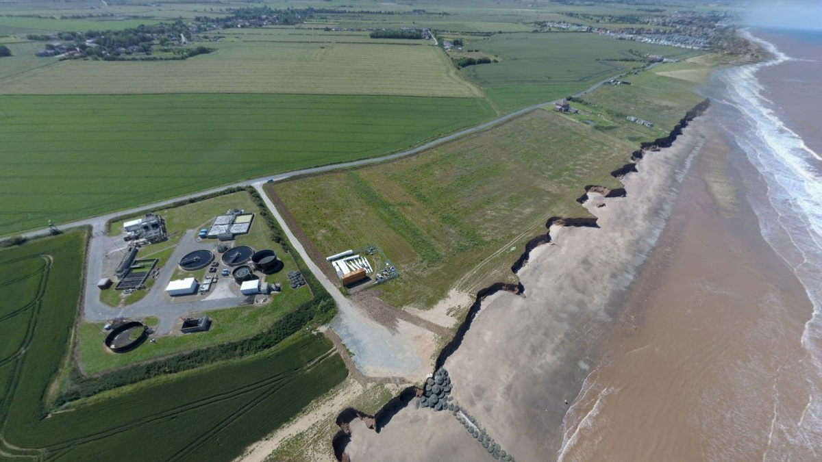
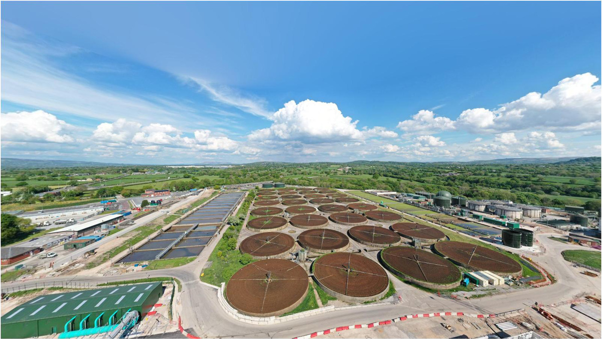
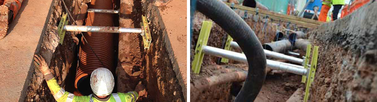
The River Humber pipeline is an important pipeline – connecting an import location for gas at Easington, on the East Yorkshire coast, to the national network – delivering gas supplies to millions of households throughout the UK.
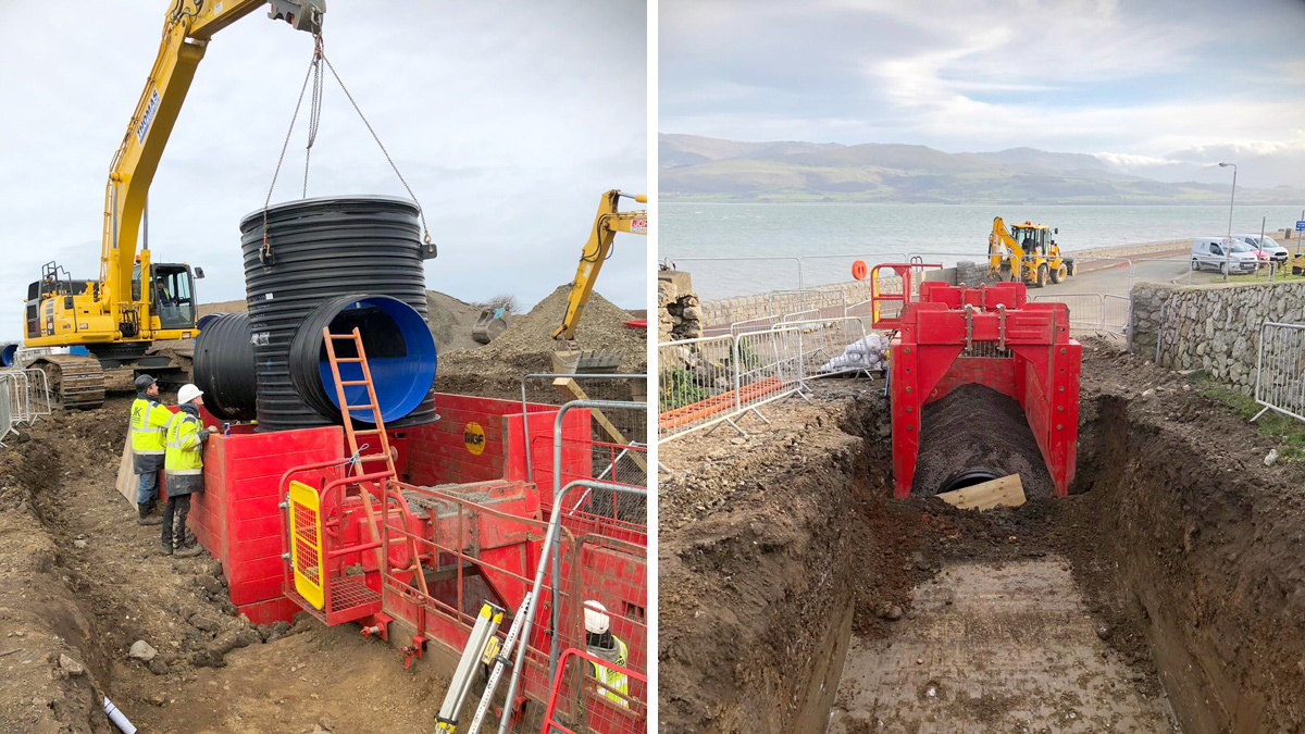
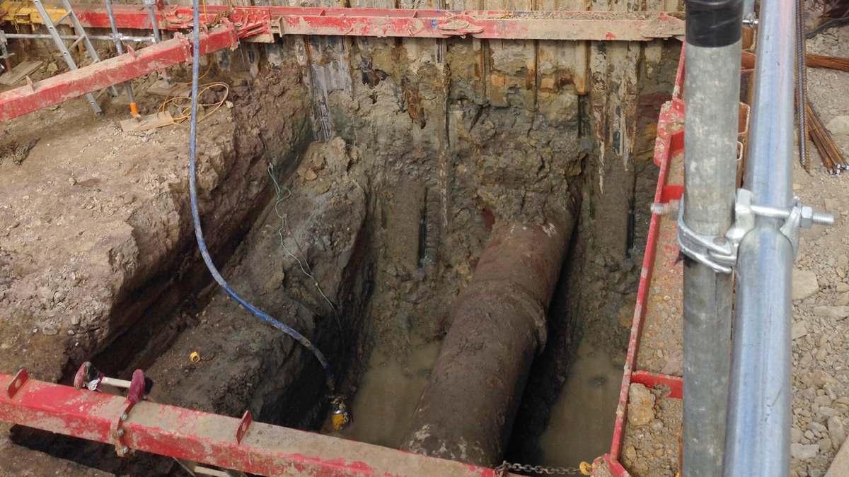
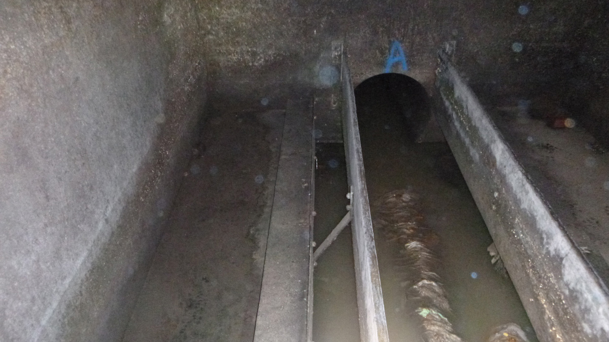
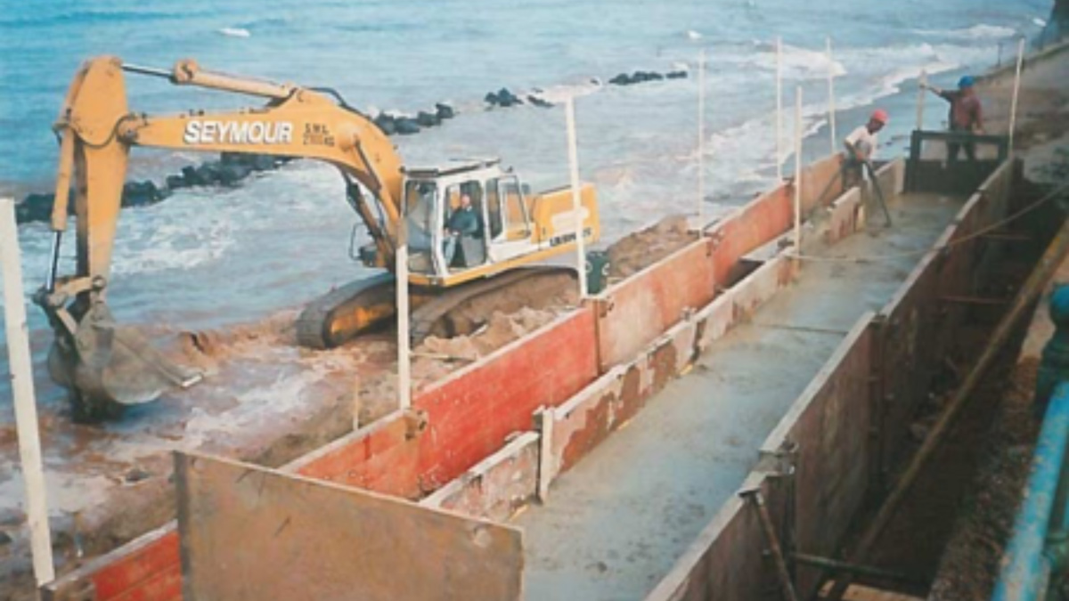
The original pipeline, Feeder 9, is buried in a cut-and-cover trench under the river bed where tidal patterns have eroded the river bed uncovering the pipeline. Remedial work was undertaken to provide a short-term solution while a long-term solution was developed.
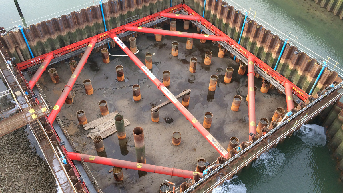
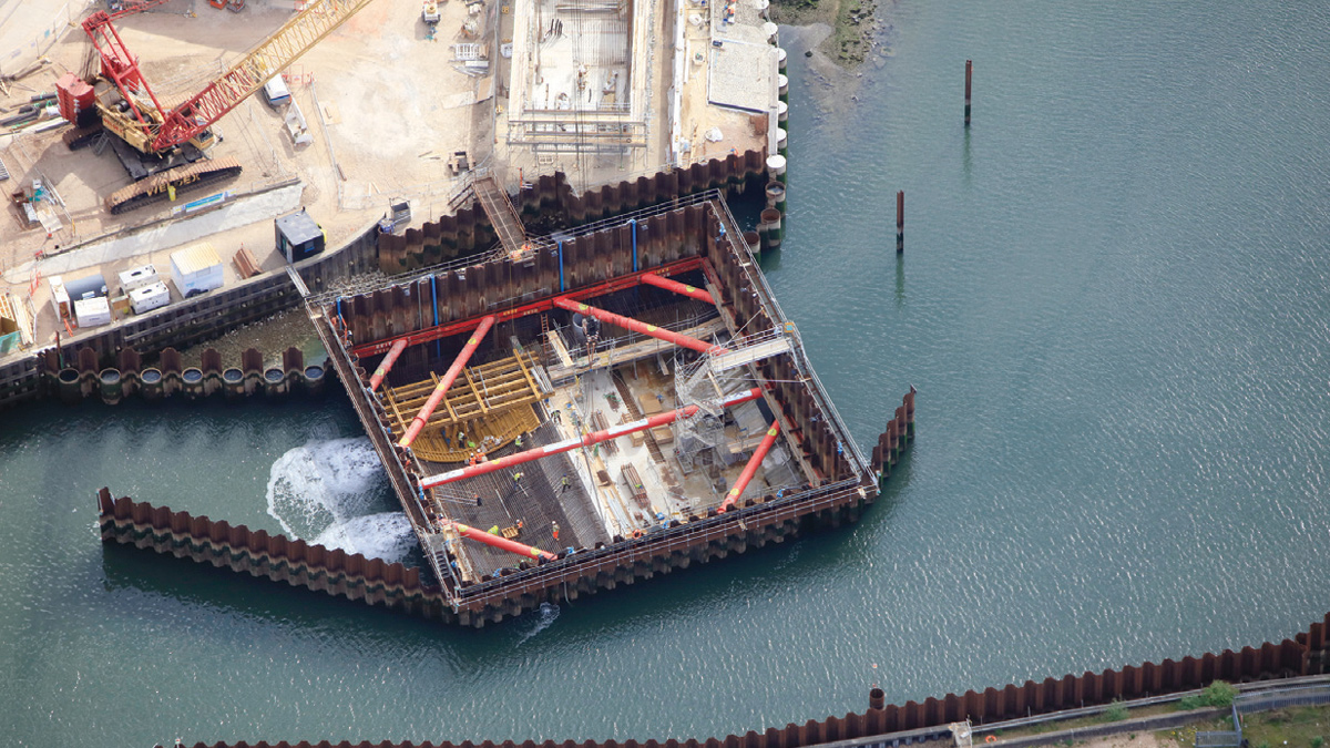
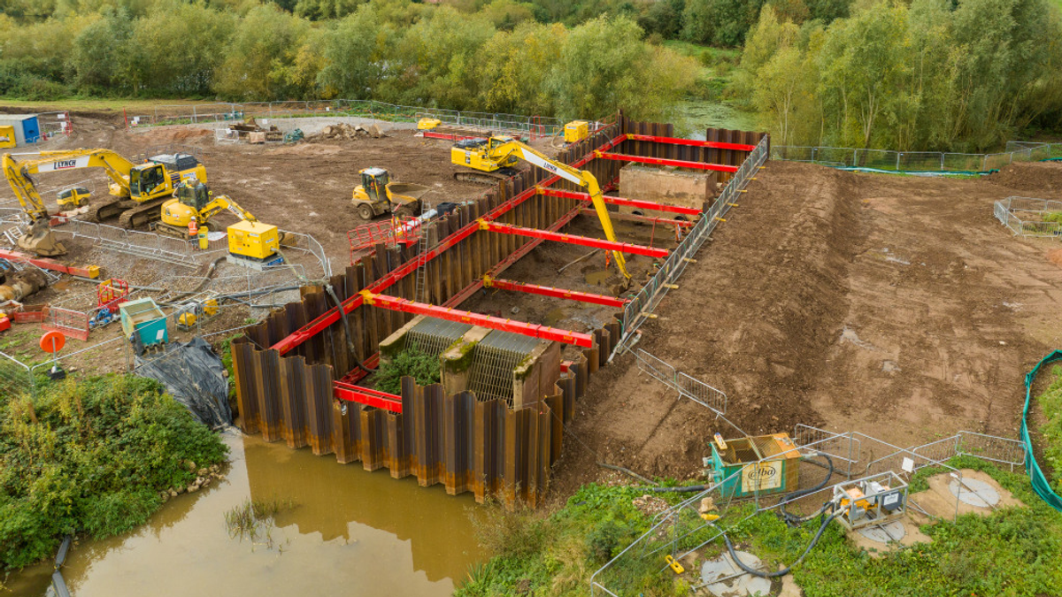
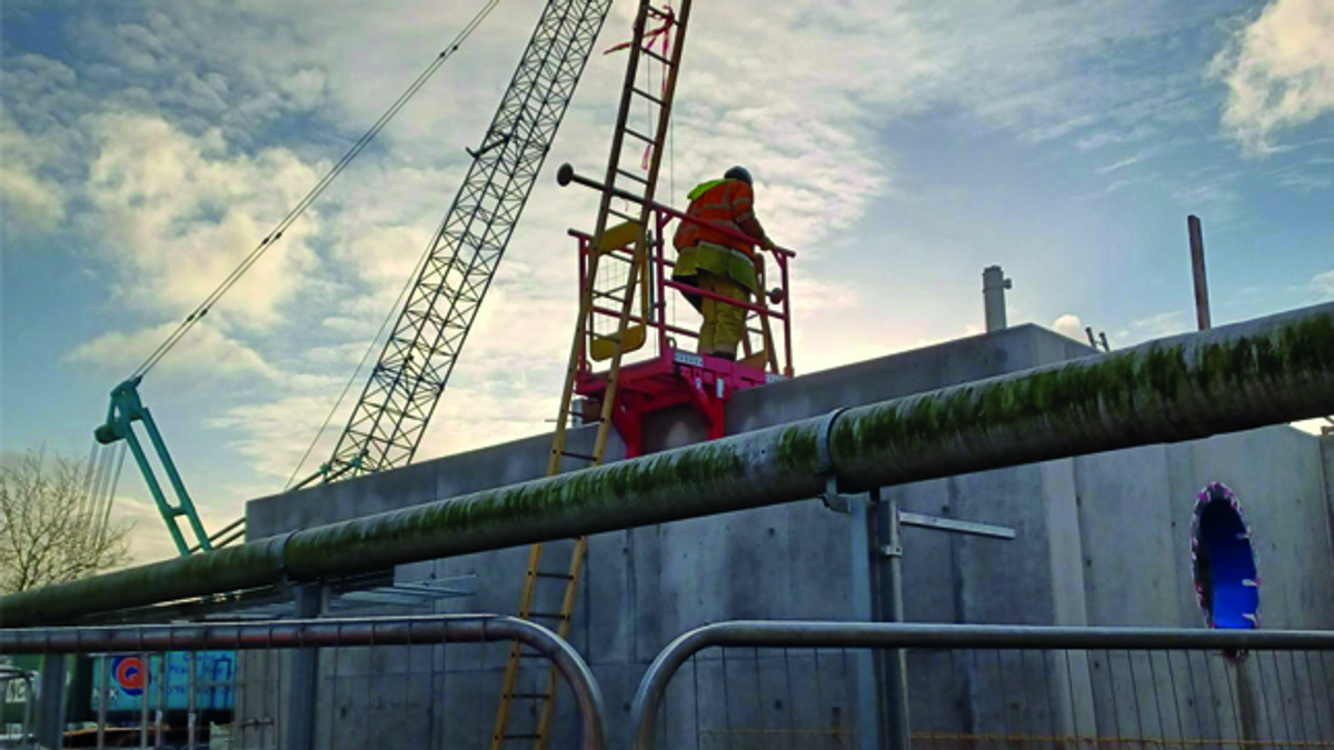
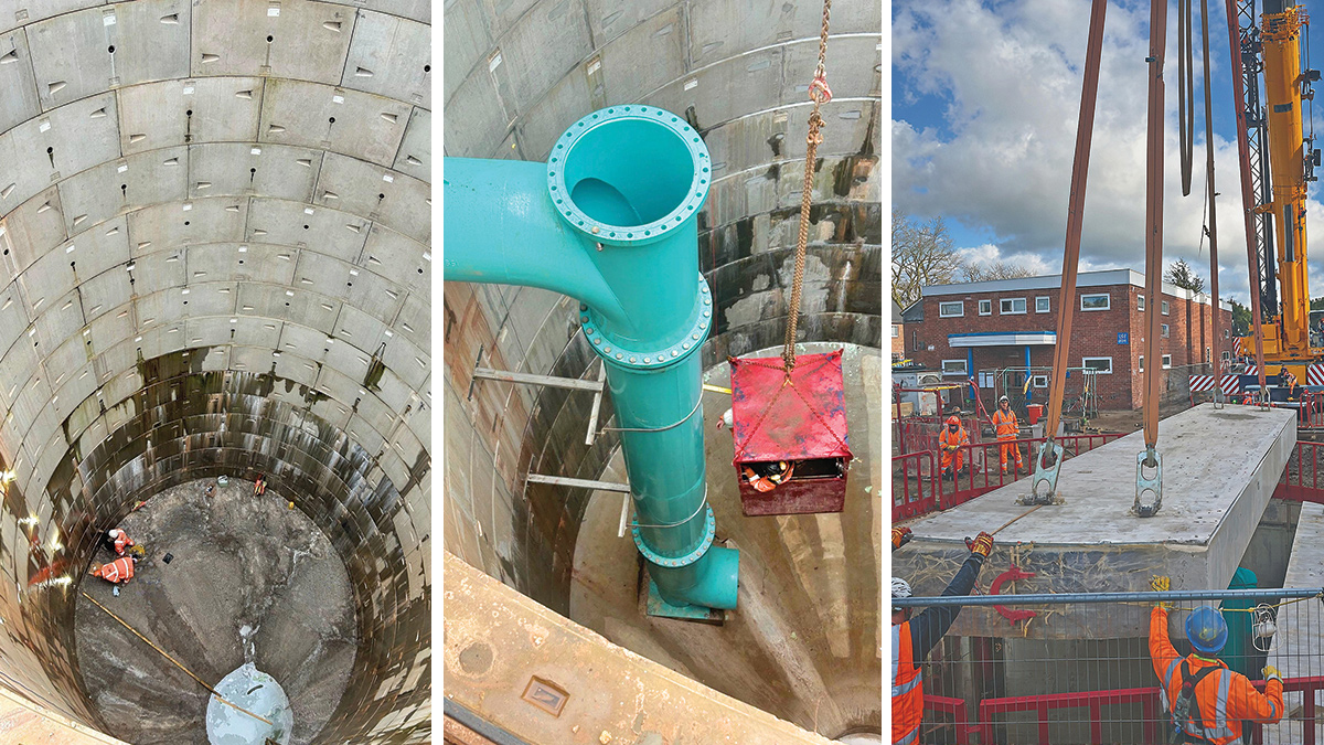
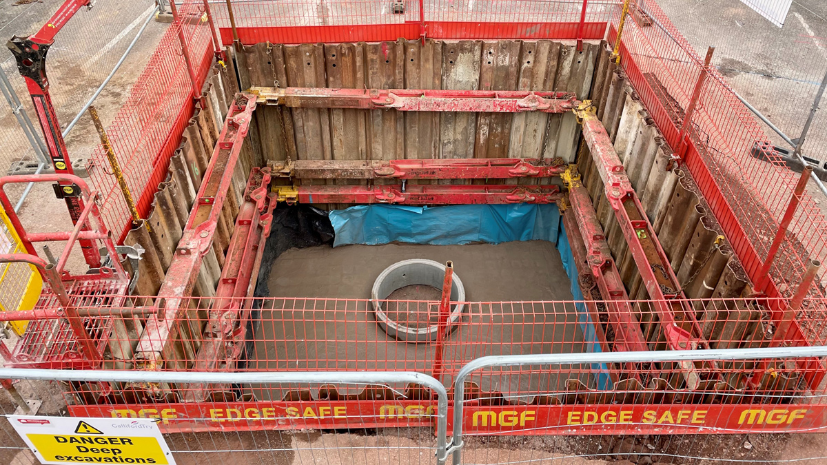
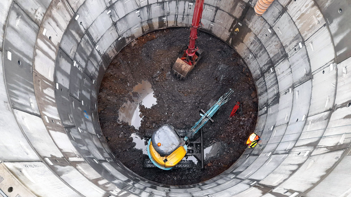
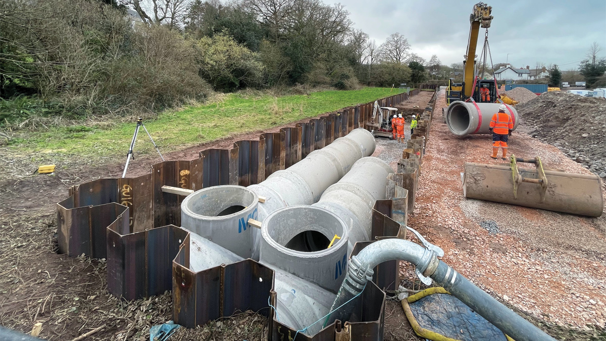
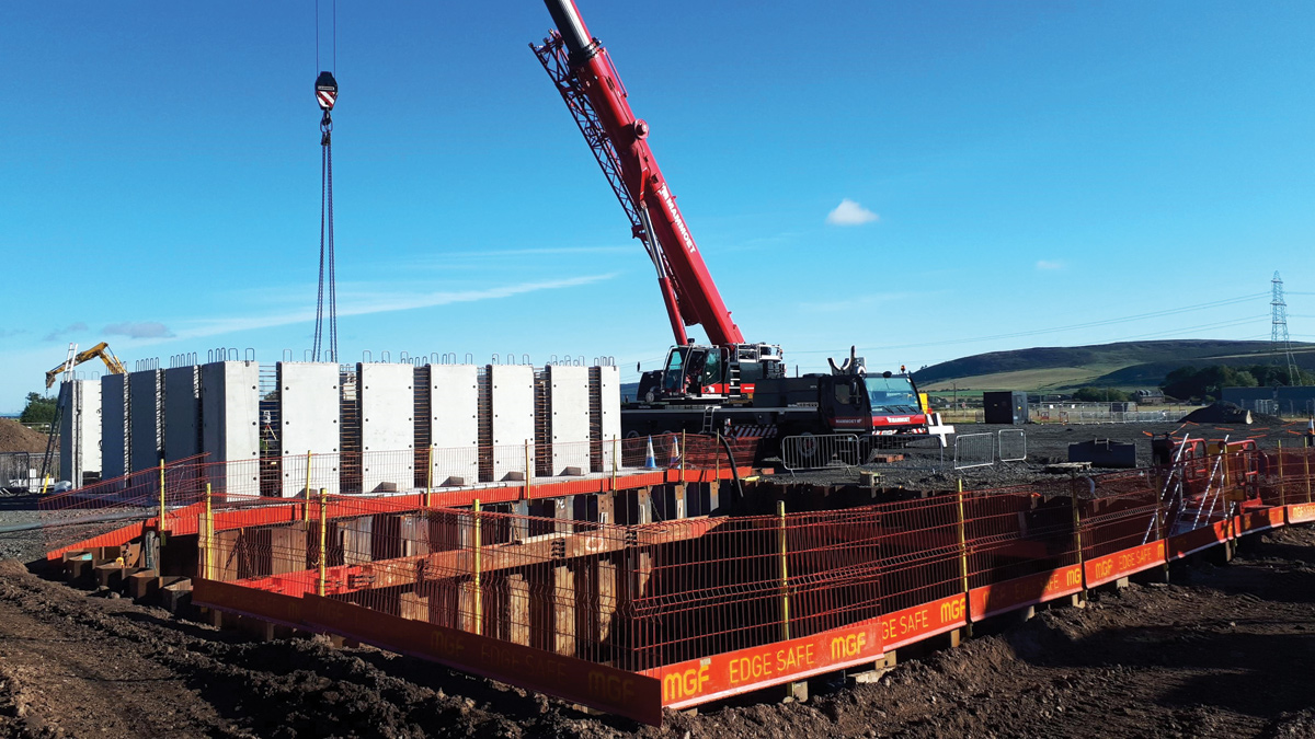
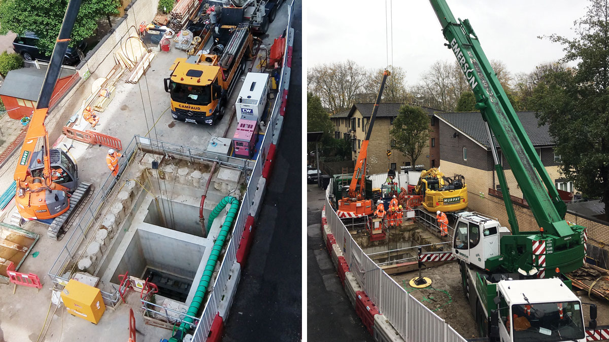
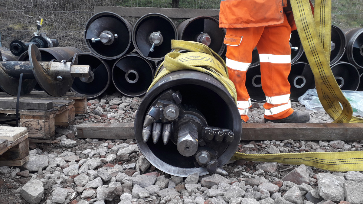
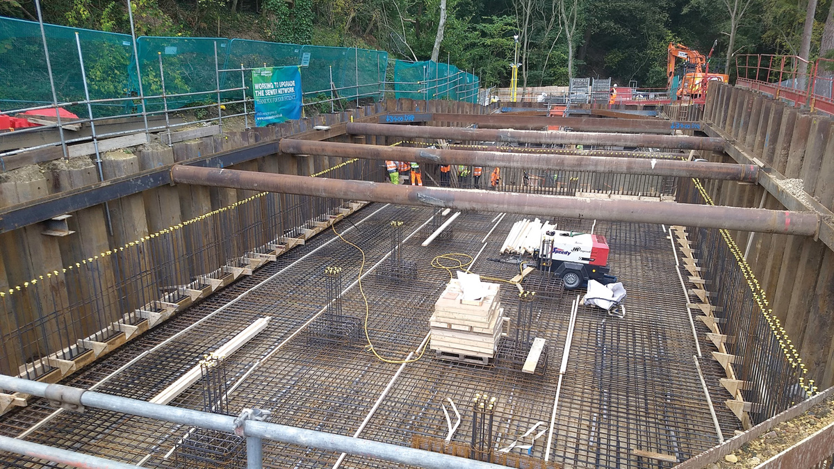
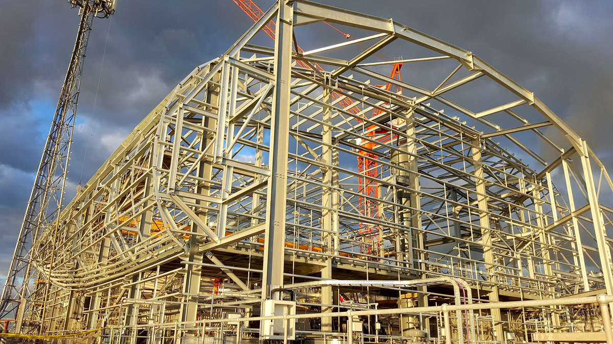
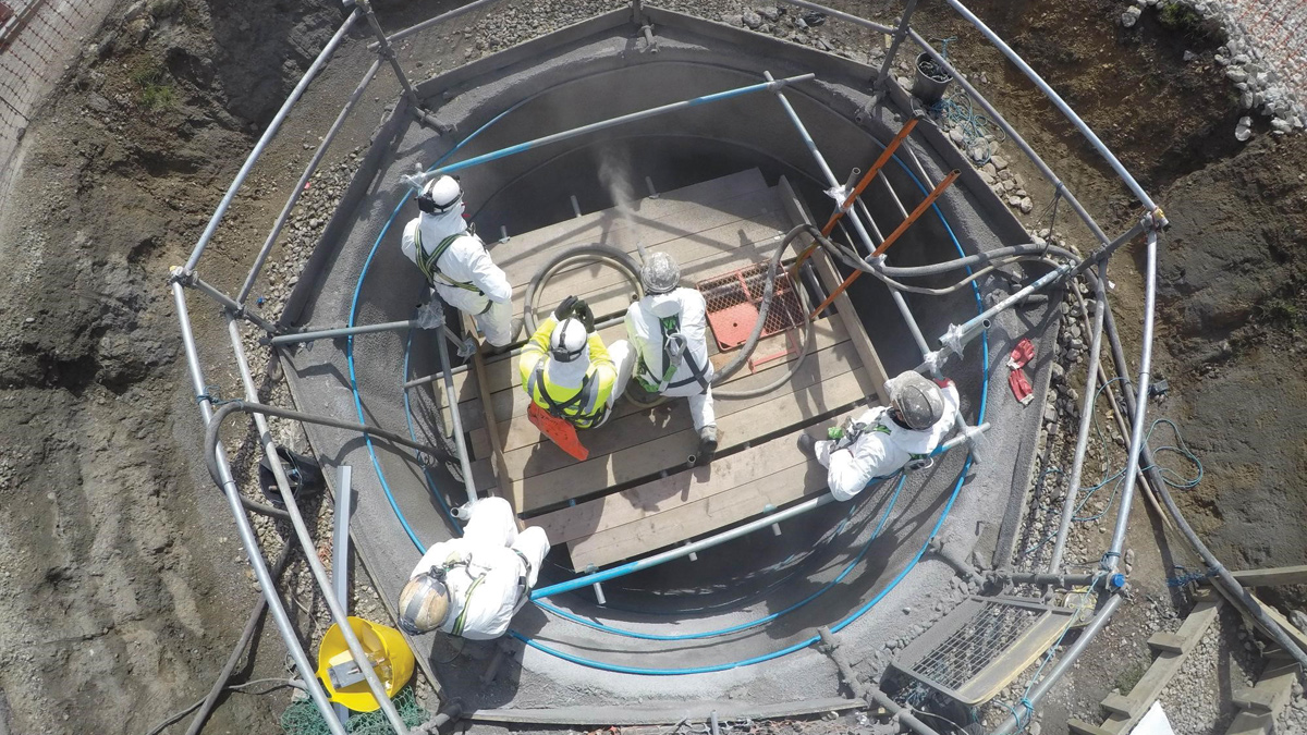
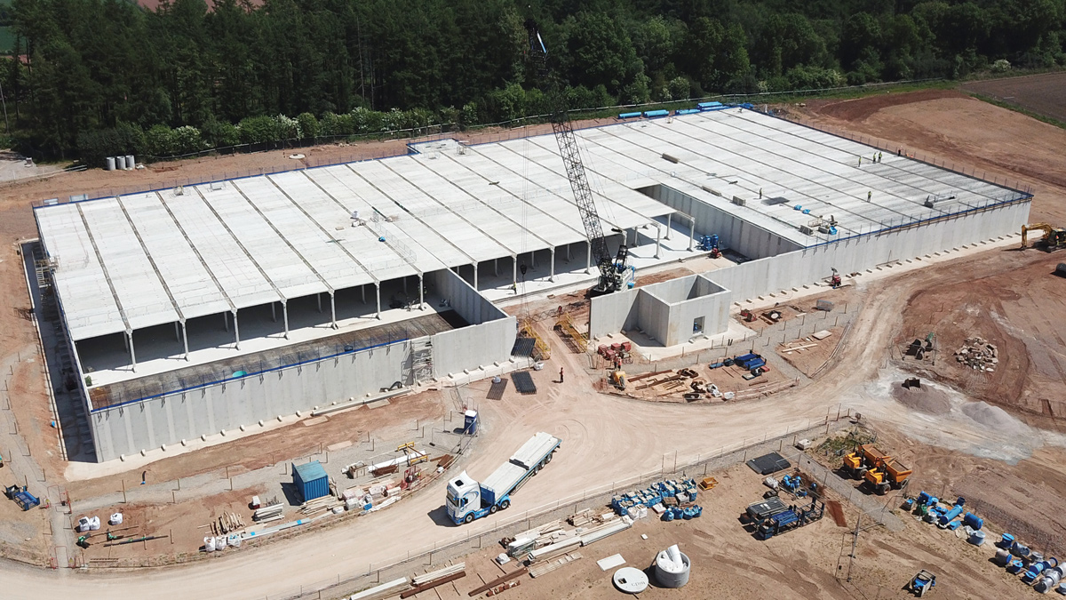
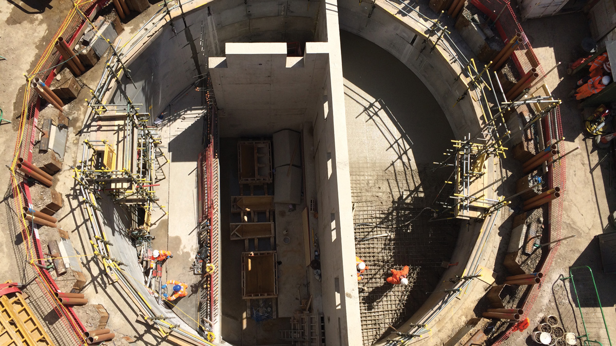
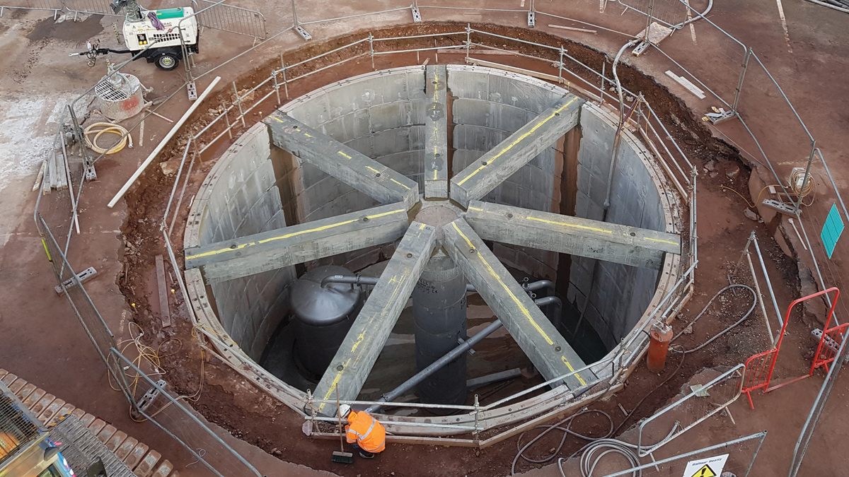
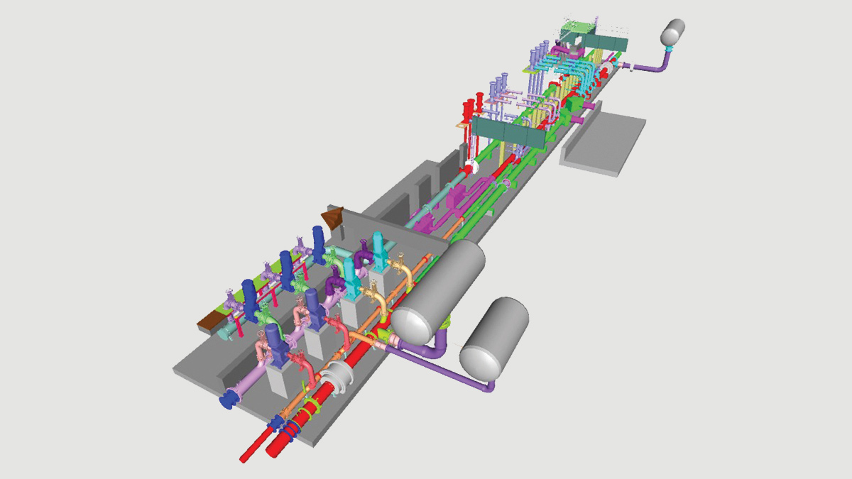
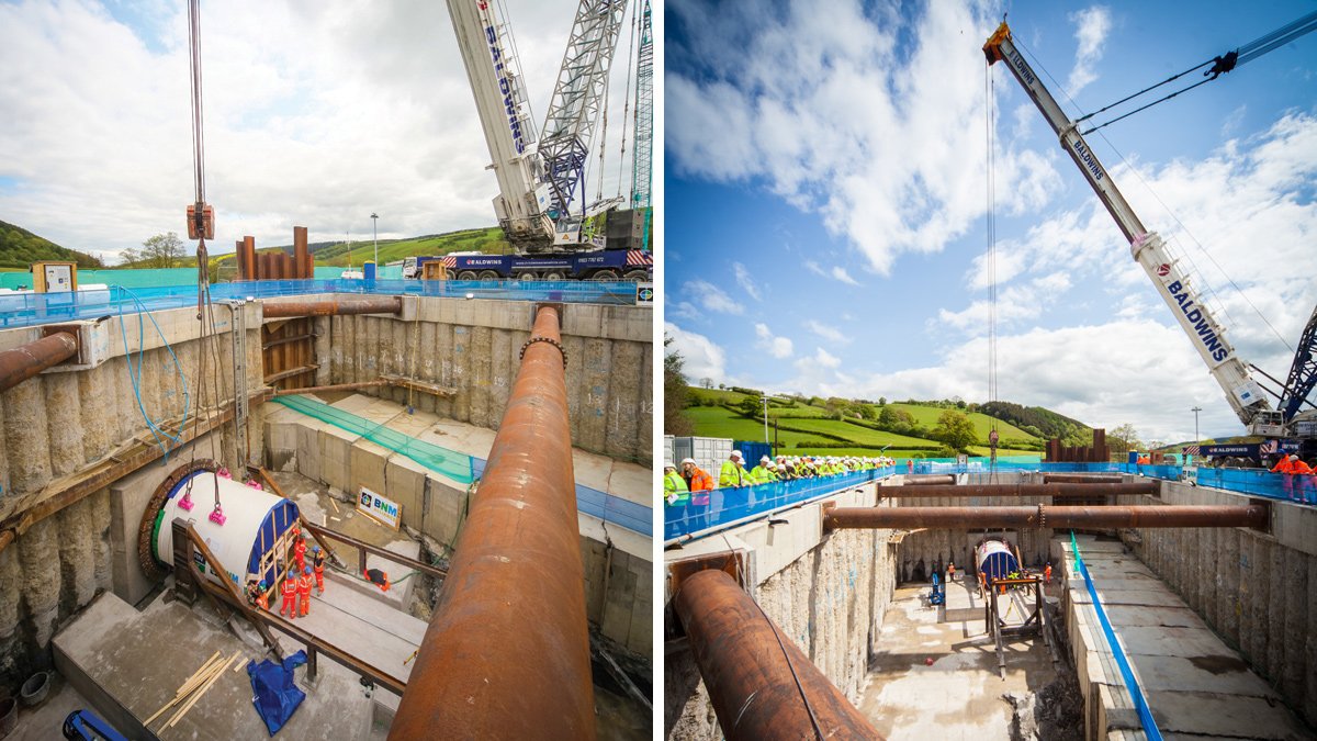
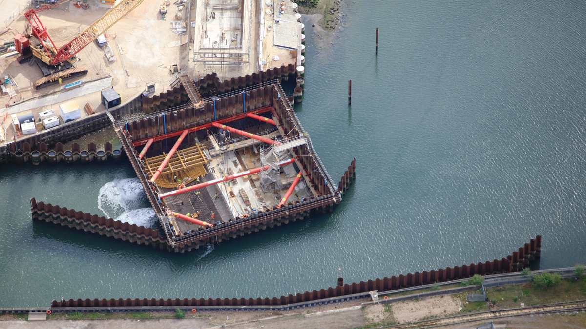
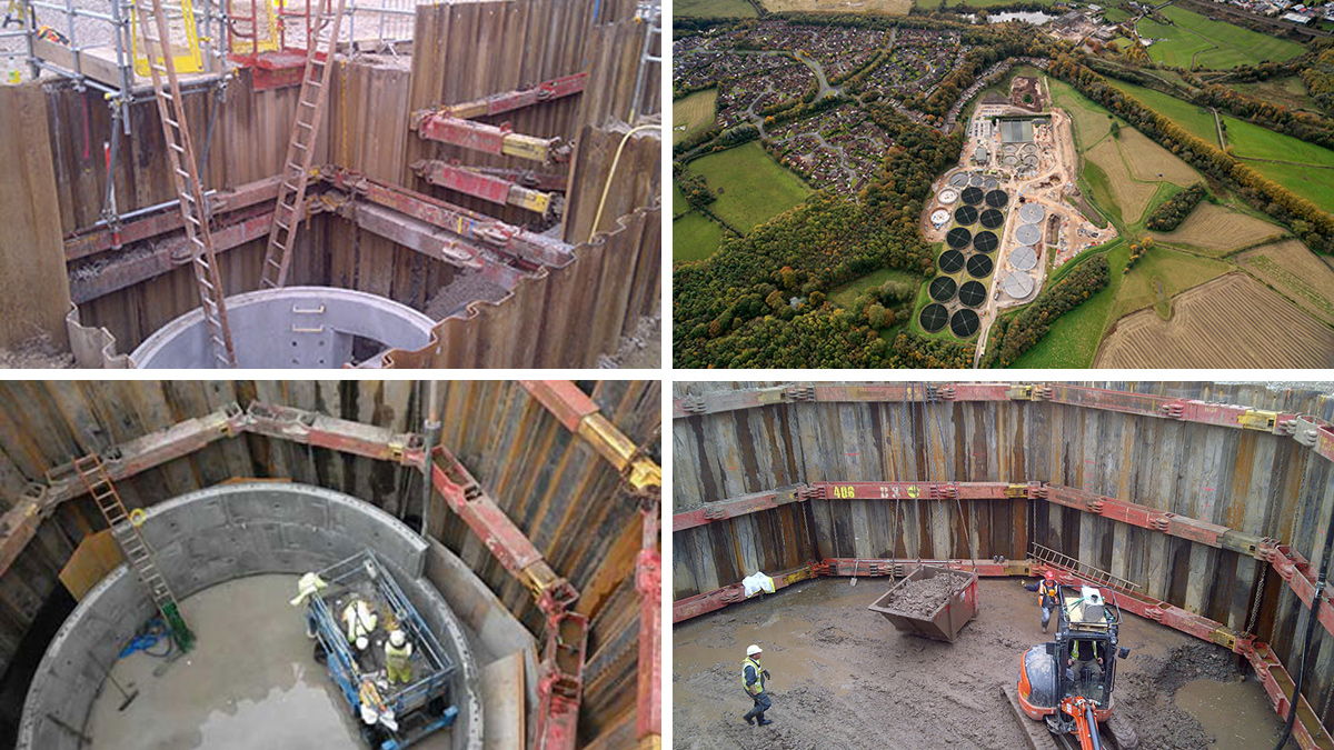
Working with the joint venture consisting of Skanska, PORR Bau GmbH and A.Hak, MGF’s in-house design engineers developed and manufactured a bespoke temporary works propping solution for the tunnel boring machine (TBM) launch pit excavation.
The contractor required the design to allow for the following key factors:
- Use of a load monitoring system.
- Design of bespoke connection details to sheet piles or capping beams where steel walers were not used.
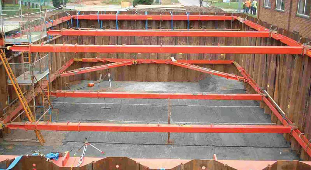
- Design of bespoke ‘headwall’ beam to eliminate knee bracing at the end of the tunnel portal to increase working space.
- Design of prop connections to withstand 10 tonne accidental load.
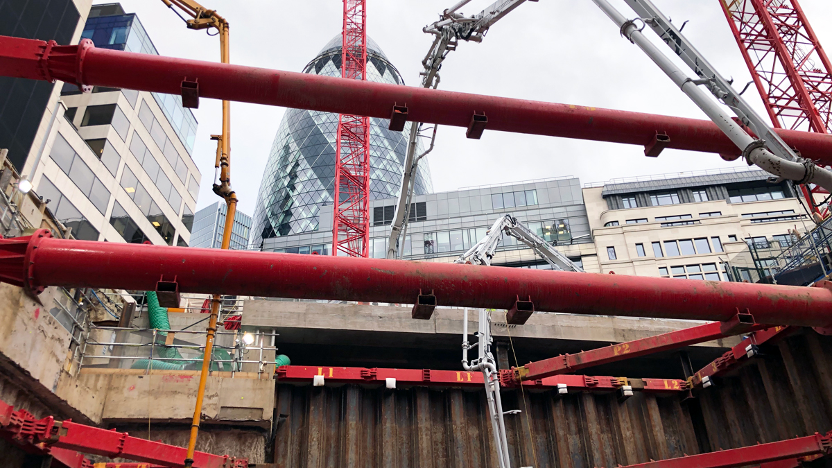
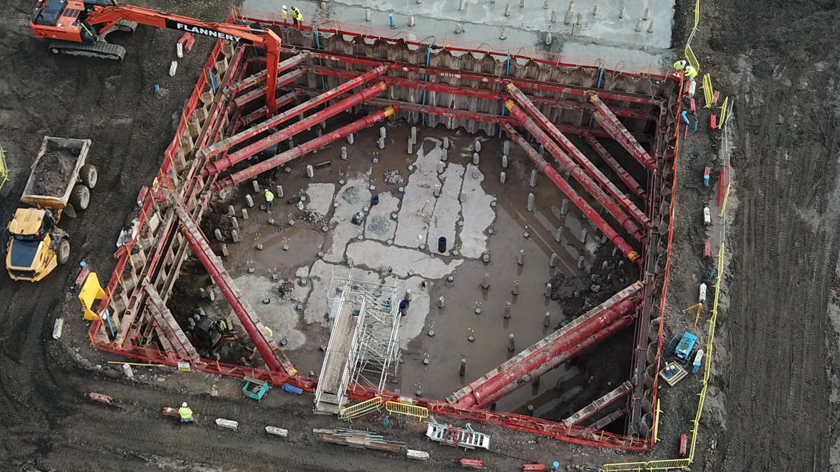
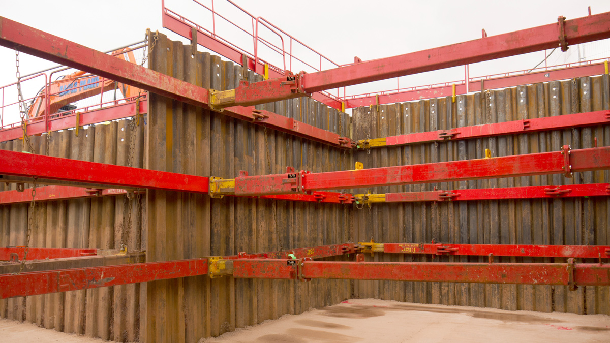
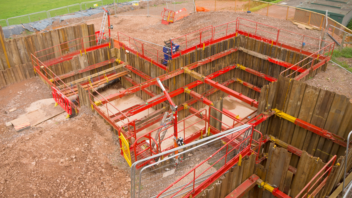
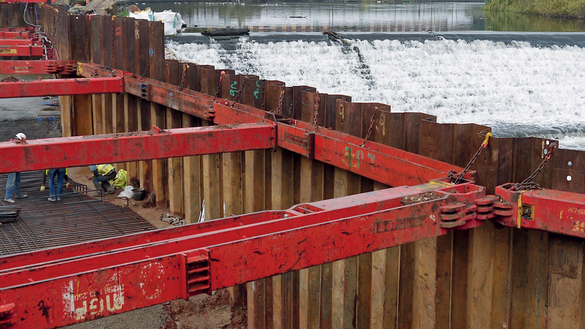
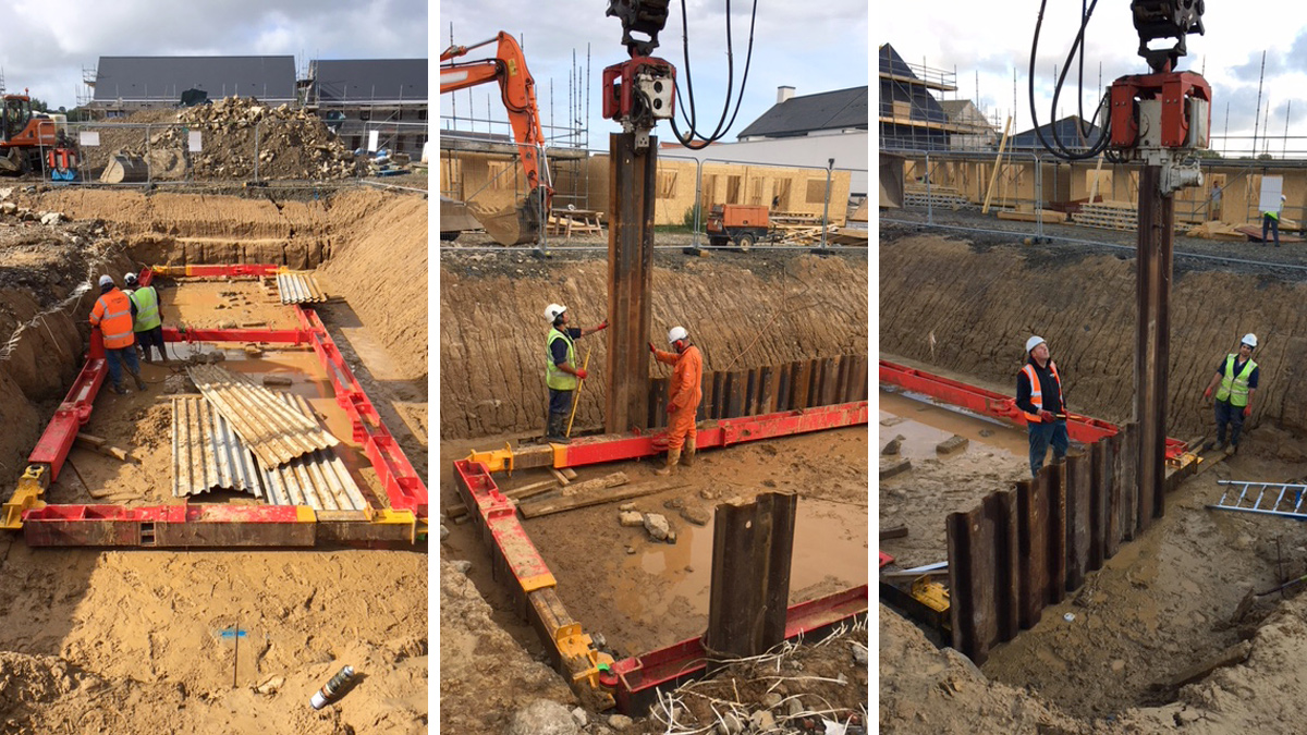
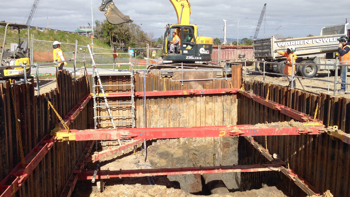
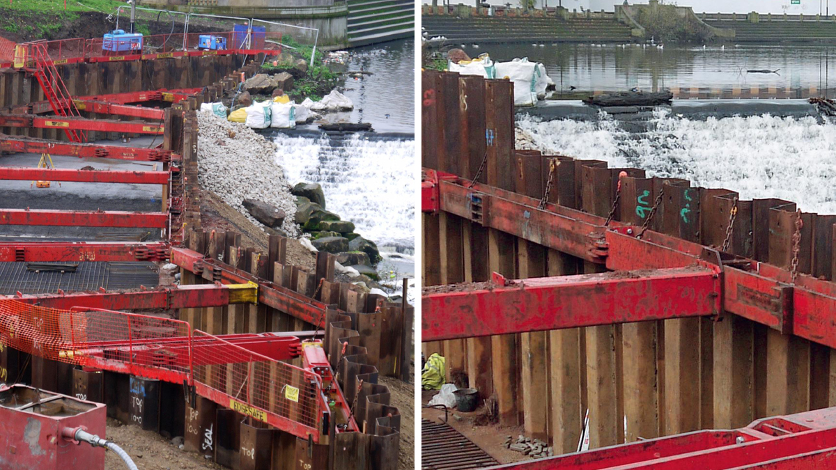
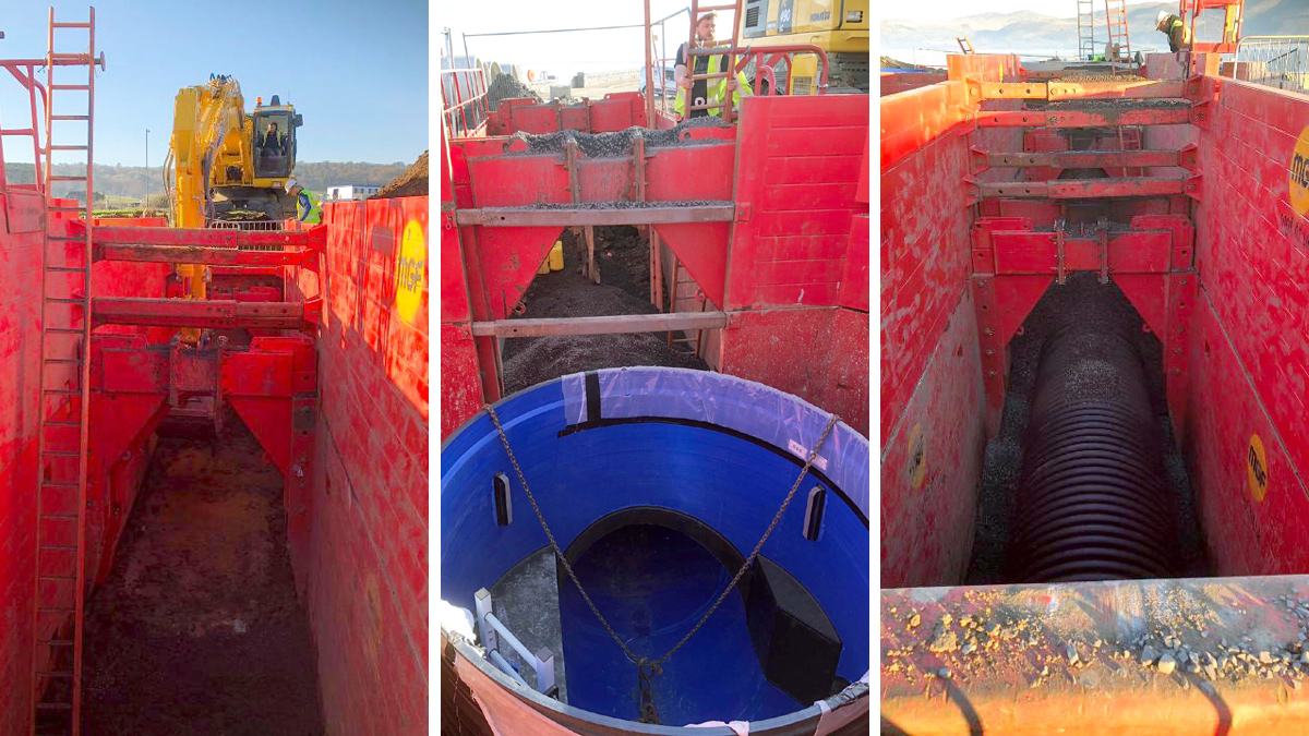
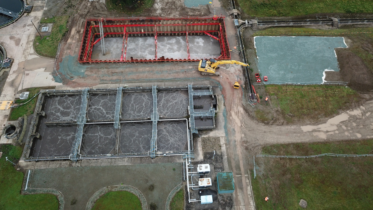
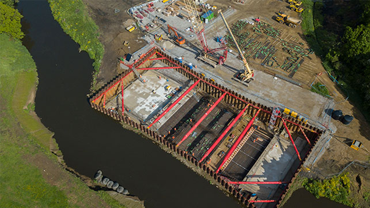
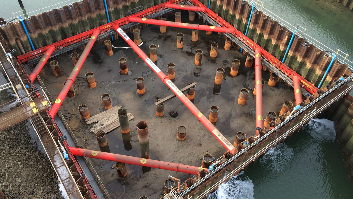
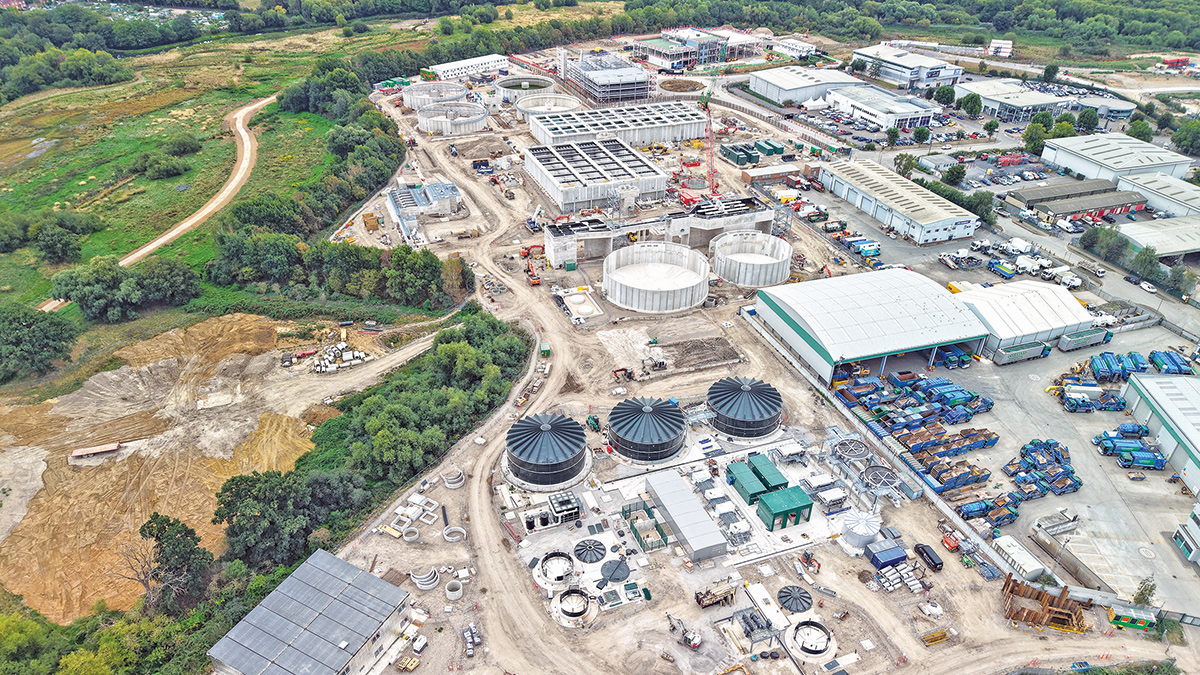
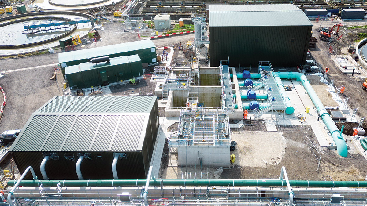
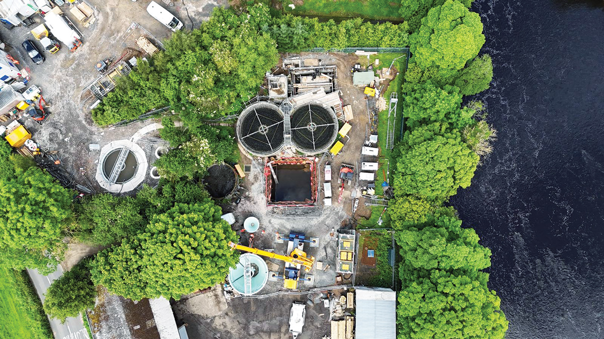
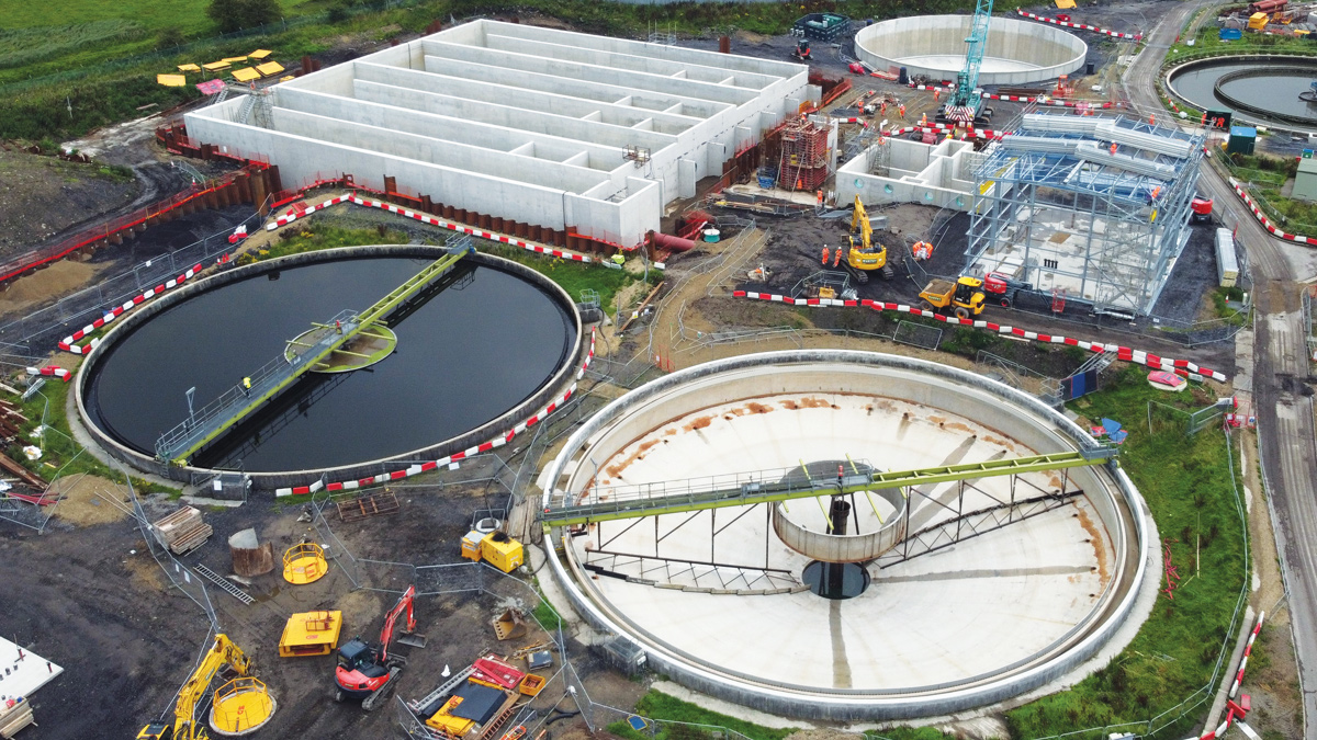
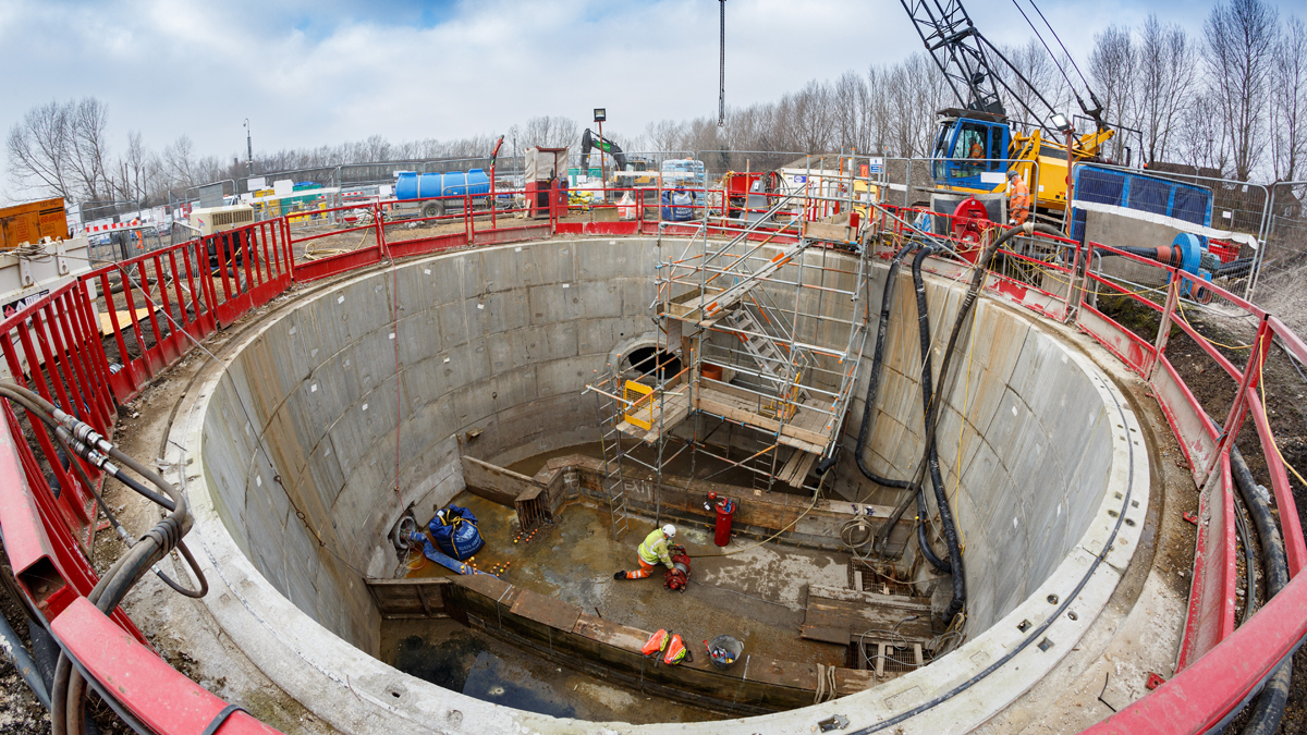
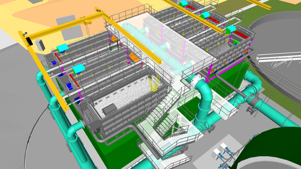
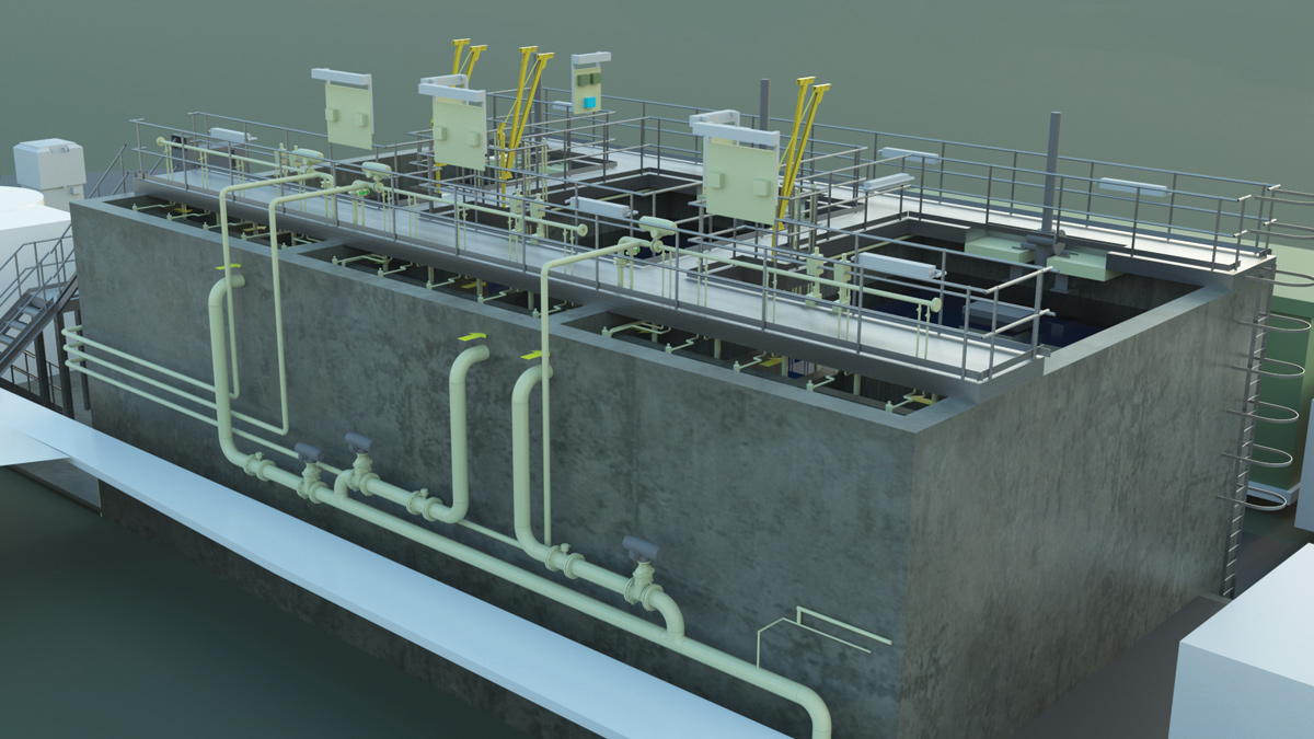
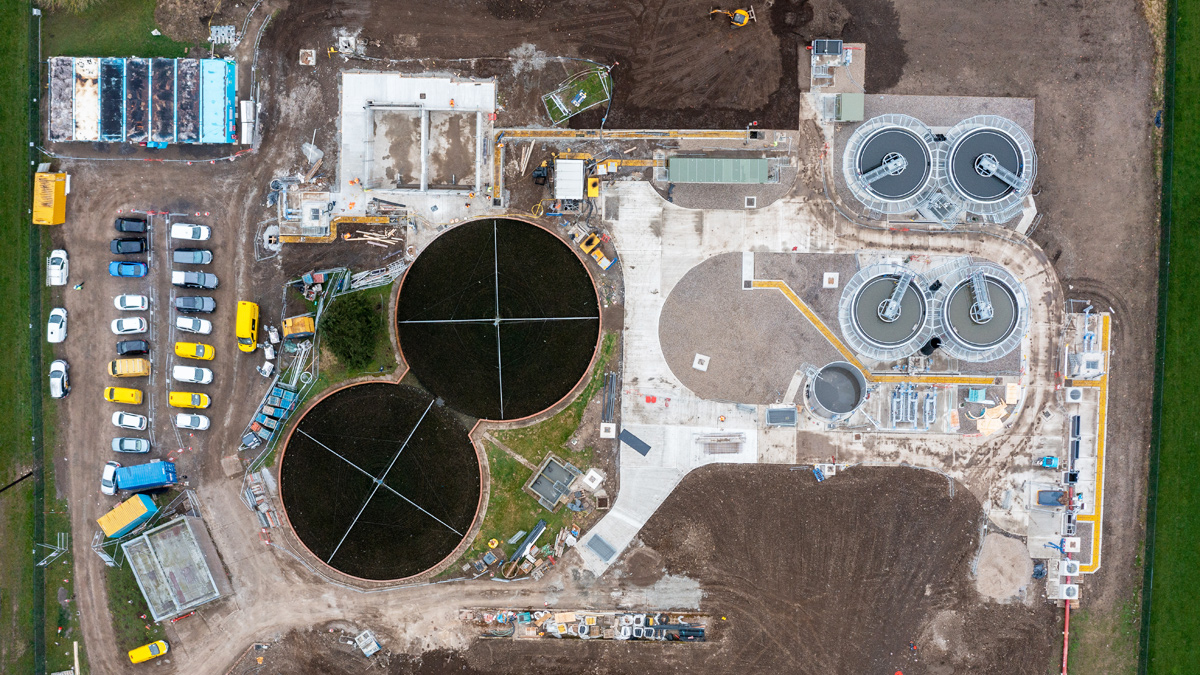
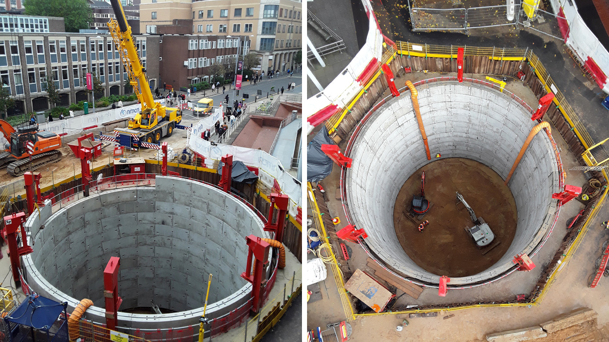
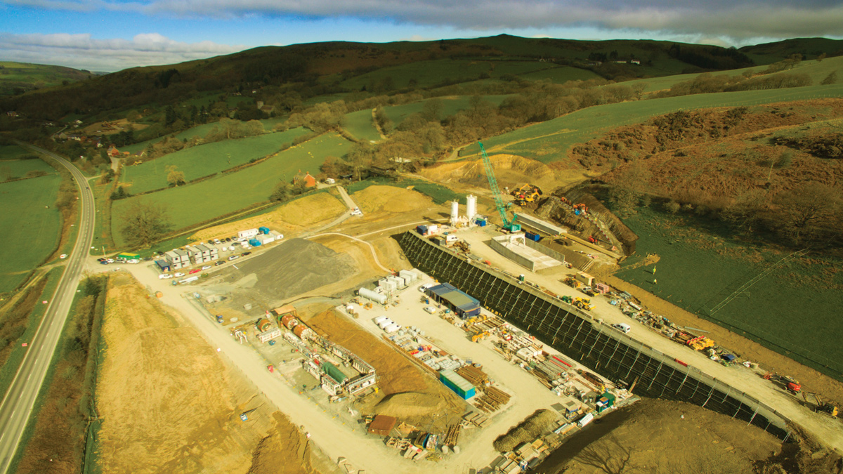
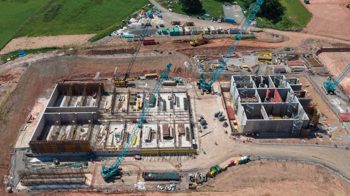
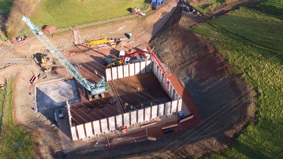
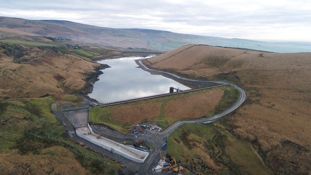
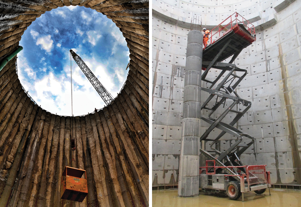
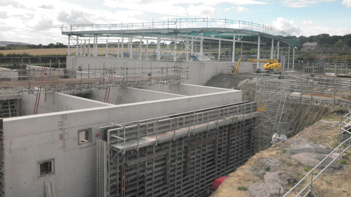
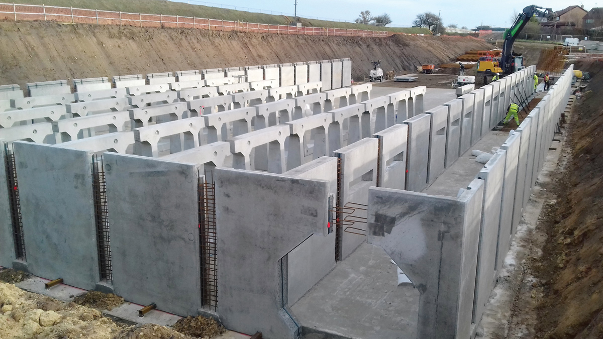
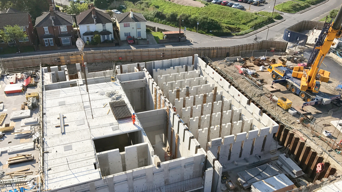
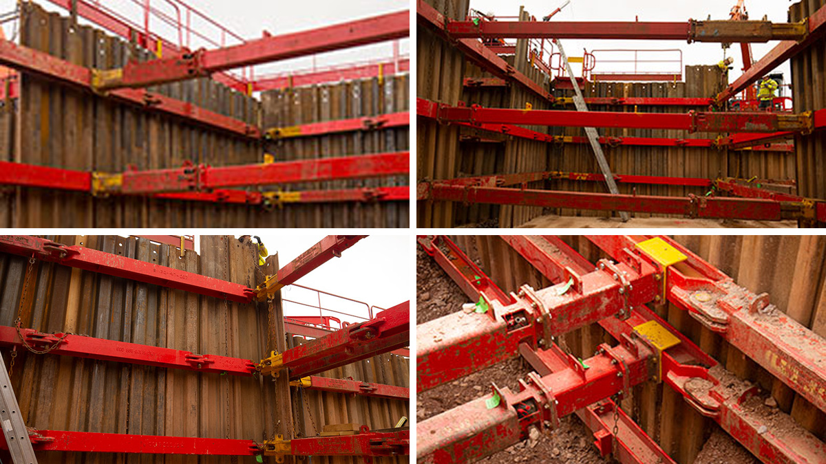
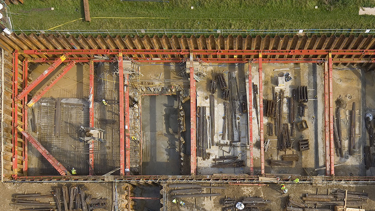
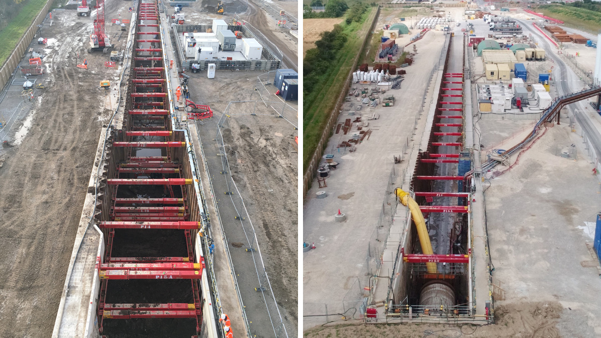
The excavation was 209m long by 8m at its widest point, ramping from ground level to 11m depth. The deepest section, including the portal wall, was constructed with secant piles with PU32 sheet piles forming the remaining walls. The propping solution consisted of 406UC hydraulic braces with 2500kN 400 series struts. To accommodate the TBM installation the longer, high-level props were twinned with spans of up to 11m between pairs of props. The headwall beam was primarily required for ease of excavation as knee braces are notoriously hard to navigate around with an excavator. This ensured that the temporary works was sufficiently robust whilst maintaining an accessible working space; a technical aspect which separated us from the competition and was completed to Eurocodes.
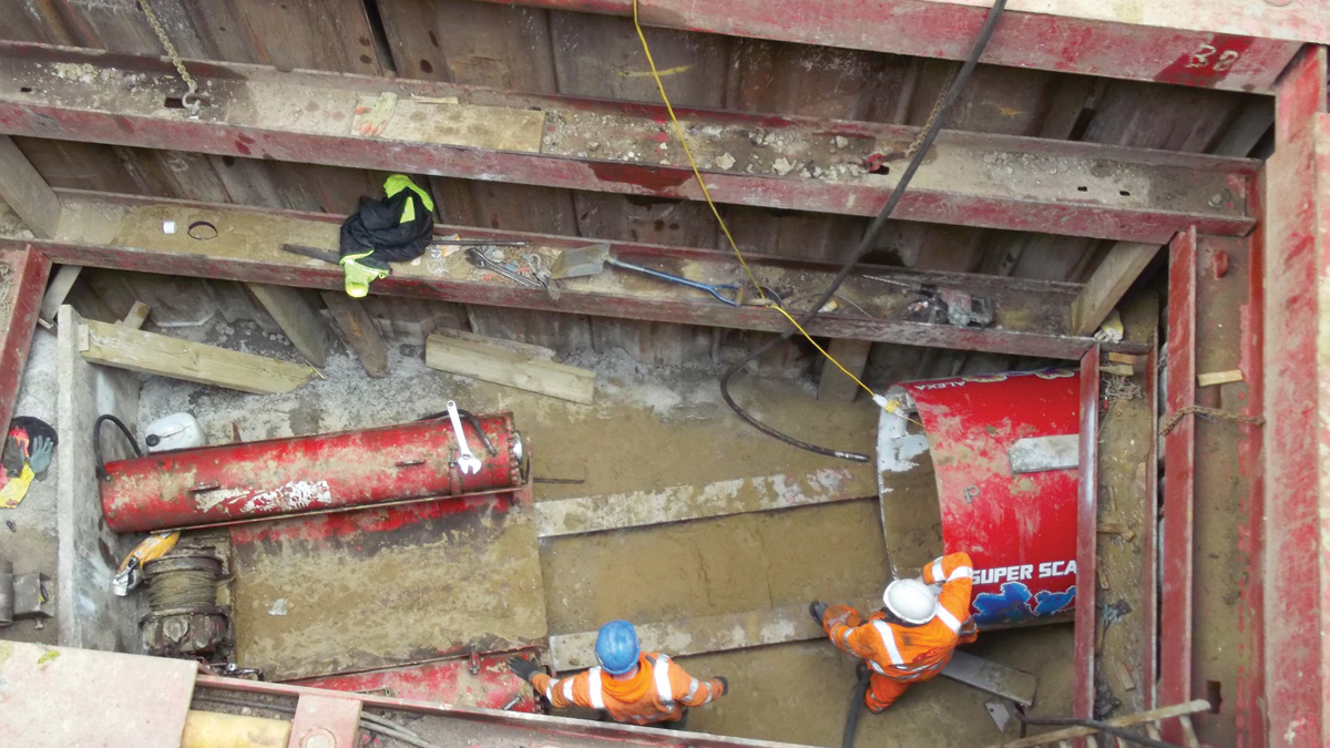
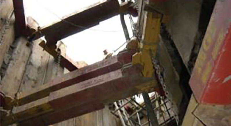
Additionally, there were concerns that accidental impact of the struts by plant could cause failure of the system, particularly during the TBM lift, as there was only 200mm space between the paired props. To mitigate this risk MGF designed bespoke connections to the capping beam, wailing beams and sheet piles to withstand an impact of 10-tonnes.
MGF used its in-house load monitoring system which actively measured the load and temperature of each individual prop, waler axial loads and bending and axil load in the headwall beam. The data collected during the monitoring regime will have a significant impact on creating efficiencies in the design of hydraulic strutting and support of narrow closed trenches going forward.
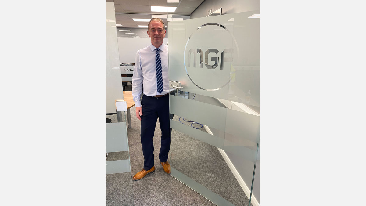
Stephen Barker, Major Projects Engineer said:
“This project was particularly challenging due to the multiple levels of framing, high loads and strict robustness criteria. As the design was required to survive the loss or damage of a prop and withstand a 10-tonne impact load more props were required, however we had to balance this with ensuring that the contractor had sufficient space to excavate efficiently. The design of the headwall beam contributed significantly to this as it removed the requirement of having knee bracing at the end of the excavation, opening space and making bulk excavation easier.”
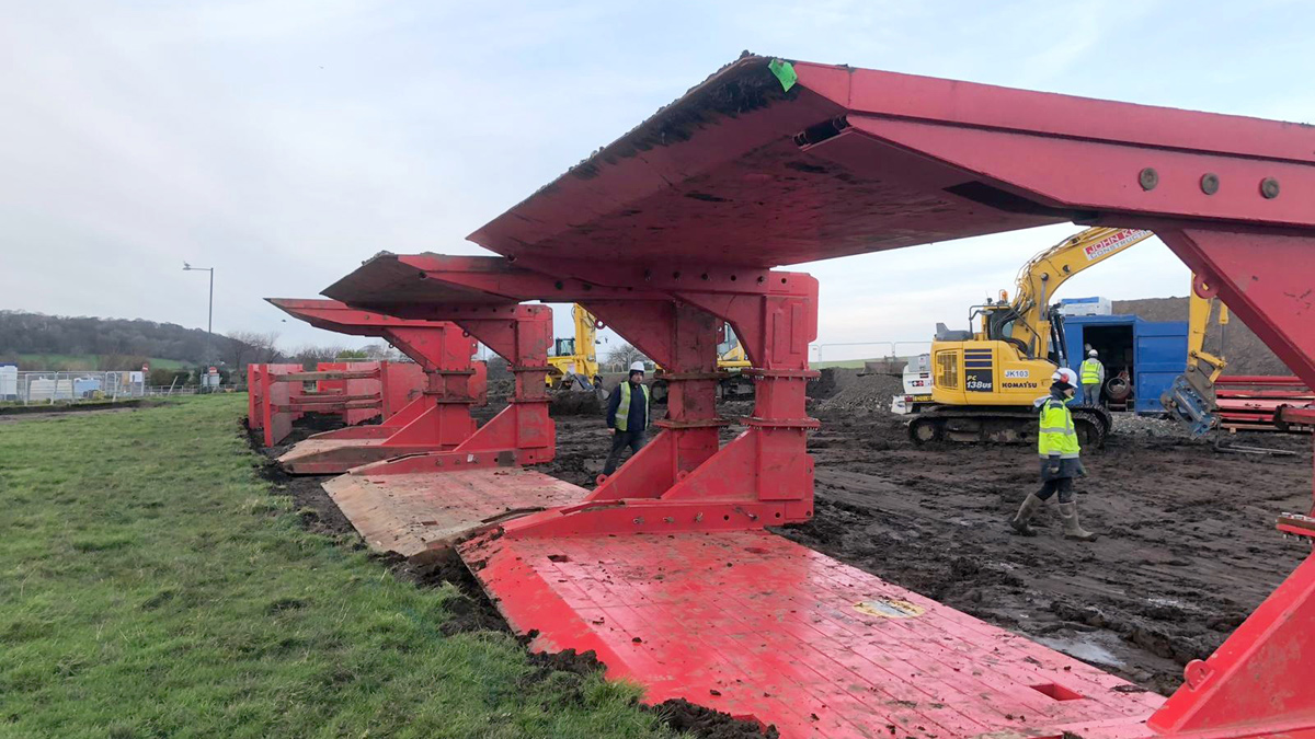
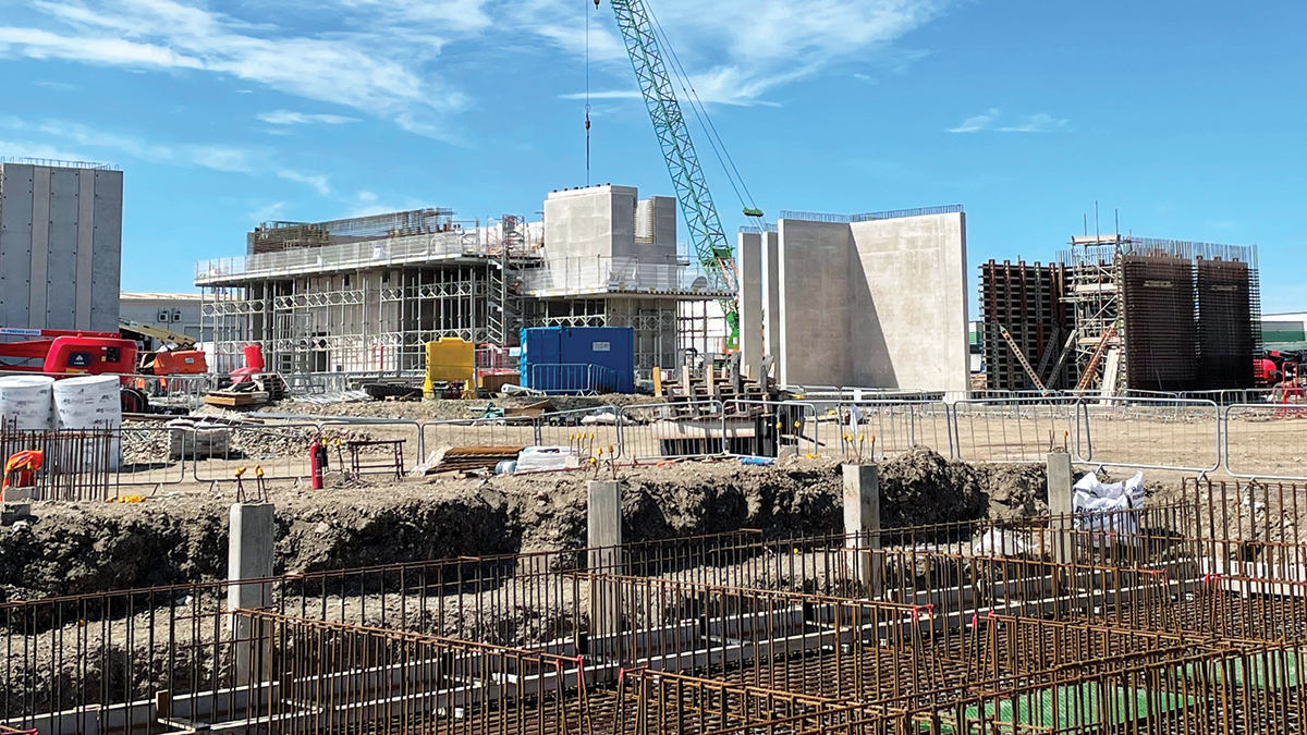
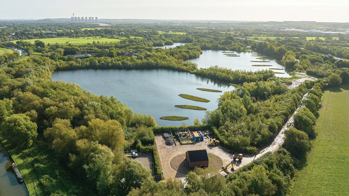
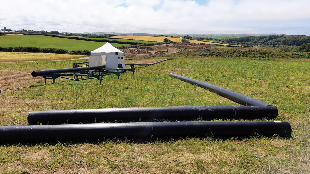
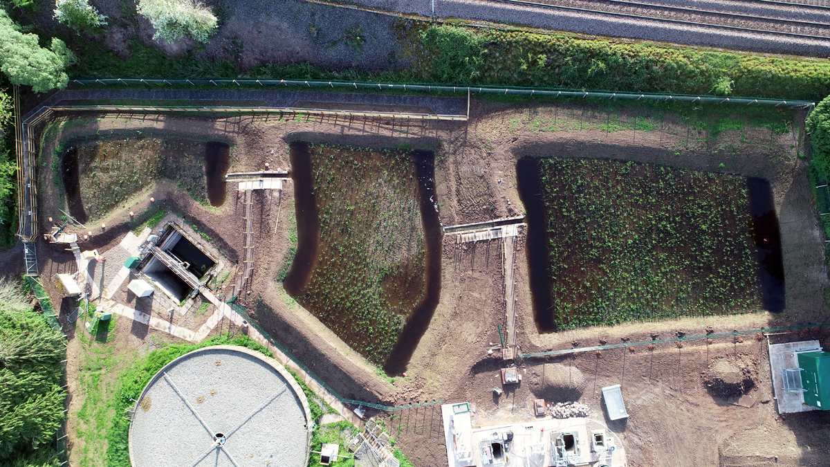
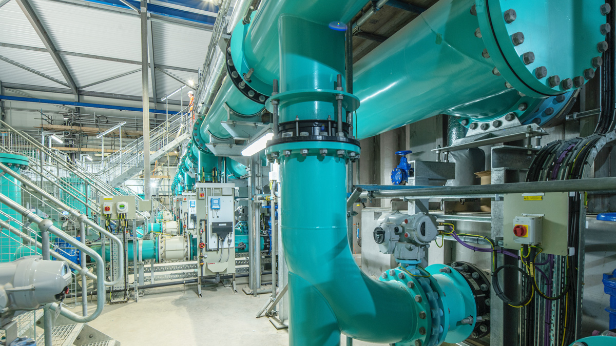
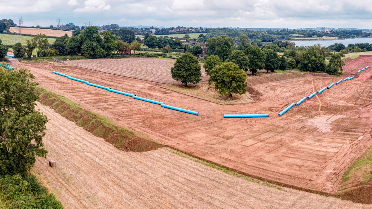
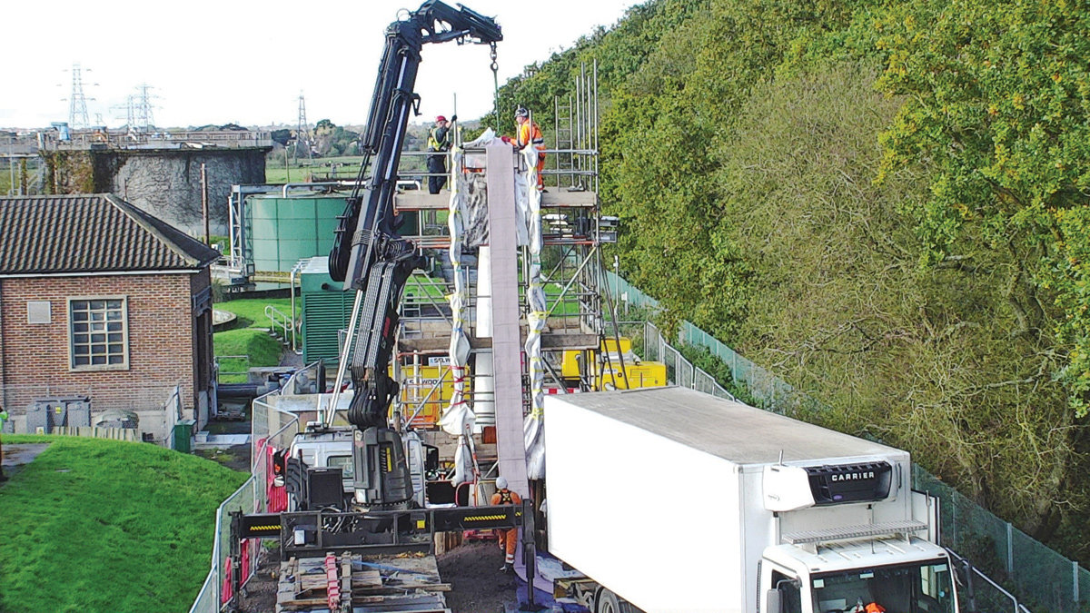
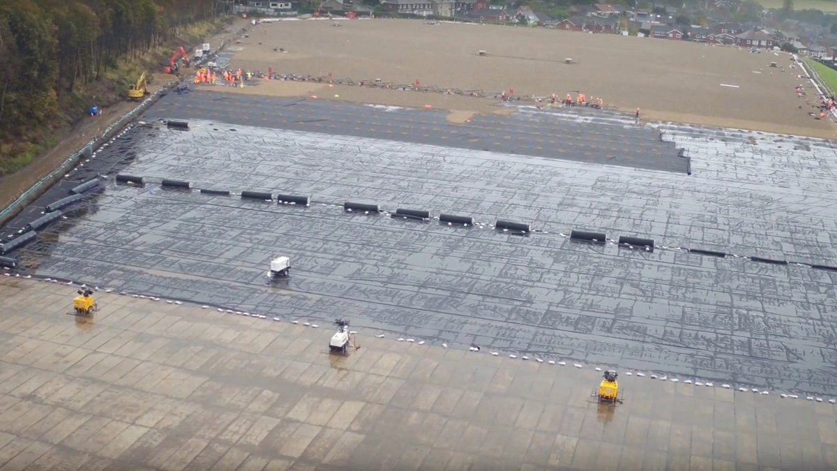
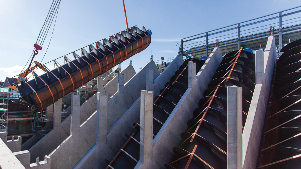
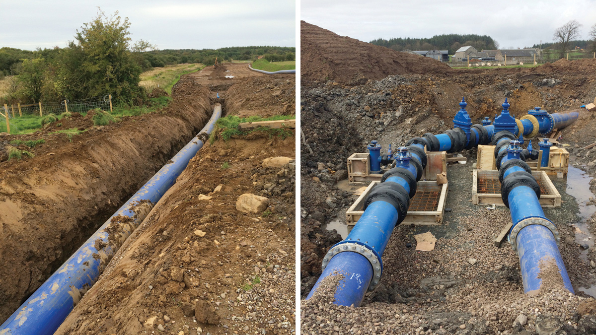
The project will take approximately two years to complete and top level of the temporary works will stay in place during this time. In an adjoining field, the pipework is being welded in top strings in readiness for insertion. The tunnelling is currently underway with a slurry TBM.
For more information: MGF Ltd | +44 (0)1942 402700 | www.mgf.co.uk
![]()
For More Information, contact us at https://mgf.co.uk/